ignition timing HONDA CR-V 1998 RD1-RD3 / 1.G Workshop Manual
[x] Cancel search | Manufacturer: HONDA, Model Year: 1998, Model line: CR-V, Model: HONDA CR-V 1998 RD1-RD3 / 1.GPages: 1395, PDF Size: 35.62 MB
Page 64 of 1395
lgnition System
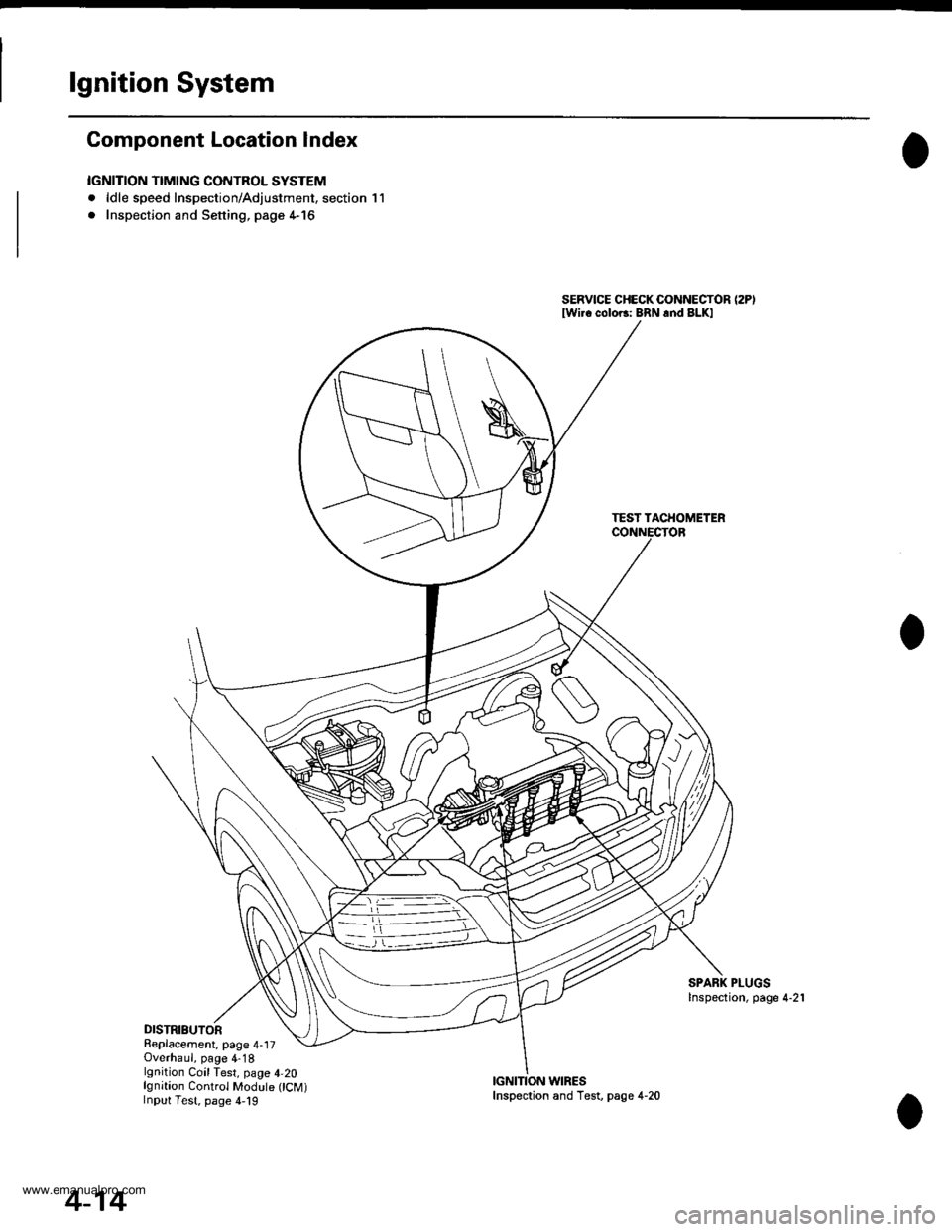
Component Location Index
IGNITION TIMING CONTROL SYSTEM
. ldle speed Inspection/Adjustment, section 11
. Inspection and Sening. page 4-16
DISTRIBUTORReplacement, page 4-17Overhaul, page 4-18lgnition CoilTest, page 4,20lgnition Control Module CM)Input Test, page 4,19
SERVICE CHECK CONNECTOR (2P)
lwi.c colo6: BRN rnd BLKI
TEST TACHOMETER
SPARK PLUGSInspection, page 4-21
WIRES
4-14
Inspection and Test, page 4-20
www.emanualpro.com
Page 66 of 1395

lgnition System
5.
lgnition Timing Inspection and Setting
2.
1.Check the idle speed, and adjust it if necessary (see
section 1 1).
Pull out the service check connector 2P (BRN and
BLK wires) from the connector holder located under
the dash on the front passenger side, then connect
the scs service connector (P/N 07PAz - 0010100) to
it.
Start the engine. Hold the engine at 3,000 rpm with
no load (A/T in N or E, Mff in neutral) until the
radiator fan comes on, then let it idle.
Connect the timing light to the No. I ignition wire,
then point the light toward the pointer on the timing
belt cover.
Check the ignition timing in no load conditions:
headlights, blower fan, rear window defogger, and
air conditioner are not operating.
lgnition Timing:
M/T: 16" 12" BTDC (RED) idling in neutral
AlTt'16" !2" BTDC (RED) idling in E or E
CRANKSHAFTPULLEY
4-16
6. lf necessary, adjust the ignition timing as follows.
Loosen the distributor mounting bolts, and turn the
distributor ignition (Dl) housing counterclockwise to
advance the timing or clockwise to retard the tim-
t no,
7.
8.
MOUNTING BOLTS24 N.m {2.4 kgf m, 17 lbtft}
Tighten the distributor mounting bolts, and recheck
the ignition timing.
Disconnect the SCS service connector from the ser-
vice check connector.
To RETARD
www.emanualpro.com
Page 67 of 1395
e
o
I'
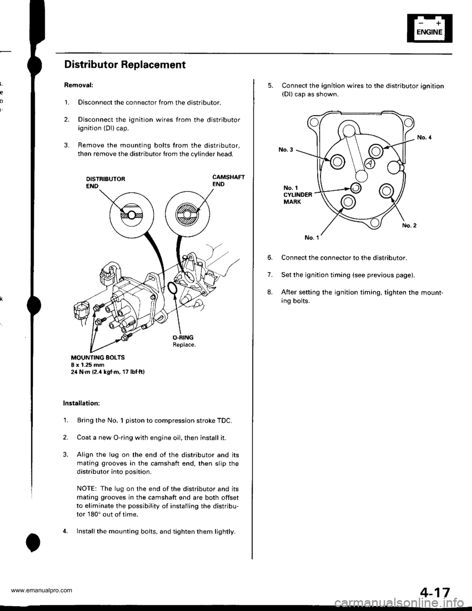
Distributor Replacement
Removal:
1. Disconnect the connector from the distributor.
2. Disconnect the ignition wires from the distributor
ignition (Dl) cap.
3. Remove the mounting bolts from the distributor,
then remove the distributor from the cylinder head.
CAMSHAFTEND
MOUNTING BOLTS8 x 1.25 mm2,1N.m {2.,1kgrf.m, 17 lbf ftl
lnstallation:
1. Bring the No. 1 piston to compression stroke TDC.
2. Coata new O-ring with engine oil, then install it.
3. Align the lug on the end of the distributor and its
mating grooves in the camshaft end, then slip the
distributor into position.
NOTE: The lug on the end of the distributor and its
mating grooves in the camshaft end are both offset
to eliminate the possibility of installing the distribu-
tor 180o out of time.
4. Installthe mounting bolts, and tighten them lightly.
5. Connect the ignition wires to the distributor ignition(Dl) cap as shown,
No. 1CYLINDERMARK
6. Connect the connector to the distributor.
7. Set the ignition timing (see previous page).
8. After setting the ignition timing, tighten the mount-
ing bolts.
4-17
www.emanualpro.com
Page 71 of 1395
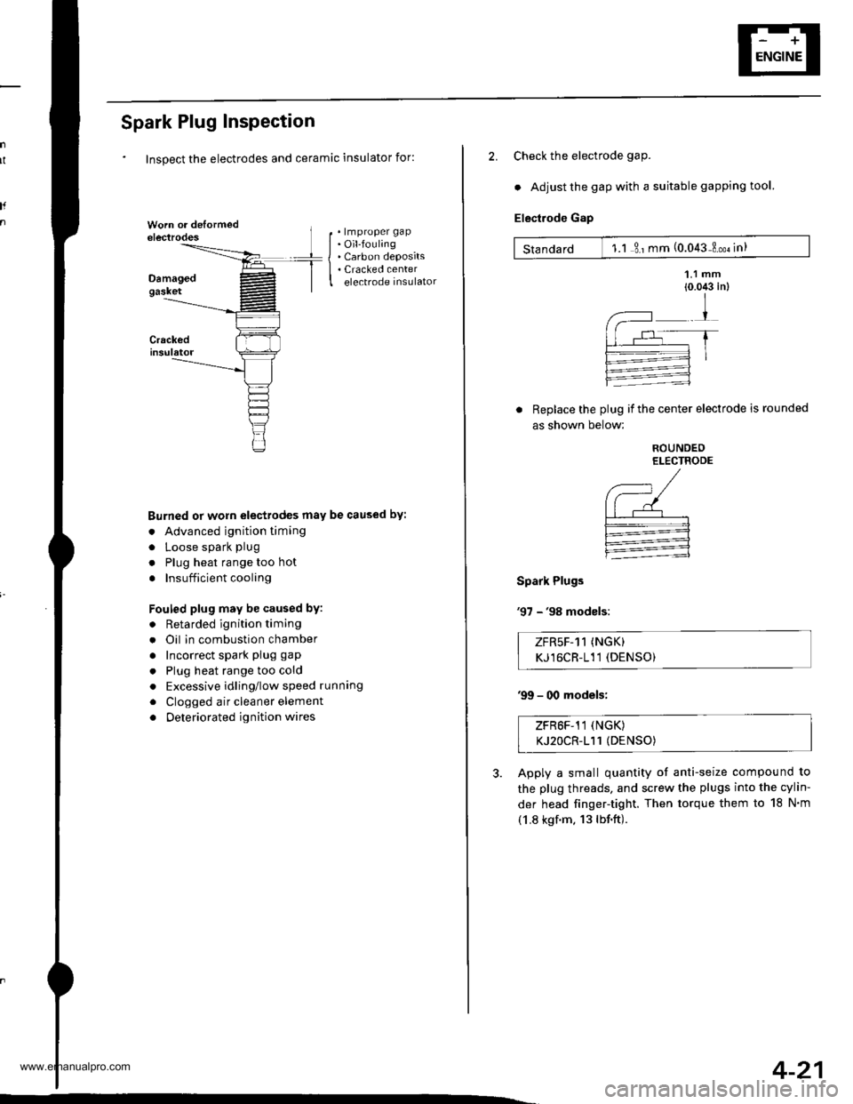
Spark Plug Inspection
Inspect the electrodes and ceramic insulator for:
. lmproper gap. Oil-fouling. Carbon deposits. Cracked centerelectrode insulator
Burned or worn electrodes may be caused by:
. Advanced ignition timing
. Loose spark plug
. Plug heat range too hot
. Insufficient cooling
Fouled plug may be caused by:
. Retarded ignition timing
. Oil in combustion chamber
. Incorrect spark plug gap
. Plug heat range too cold
. Excessive idling/low speed runnang
. Clogged air cleaner element
. Deteriorated ignition wires
I
2. Check the electrode gaP.
. Adjust the gap with a suitable gapping tool.
Electrode Gap
Standard 1.1 3 ' mm (0.043 Loo. in)
Replace the plug if the center electrode is rounded
as shown below:
Spark Plugs
'97 - '98 modsls:
ROUNDEOELECTRODE
,--, /(--/| | r--'--'--r-.--l-:=---:1
:
ZFR5F-11 (NGK)
KJ16CR-111 (DENSO)
'99 - 00 models;
ZFR6F-11 (NGK)
KJ2OCR-111 (DENSO)
Apply a small quantity of anti-seize compound to
the plug threads, and screw the plugs into the cylin-
der head finger-tight. Then torque them to 18 N'm
(1.8 kgf.m. 13lbf.ft).
4-21
www.emanualpro.com
Page 268 of 1395
Troubleshooting
Troubleshooting Procedures (cont'd)
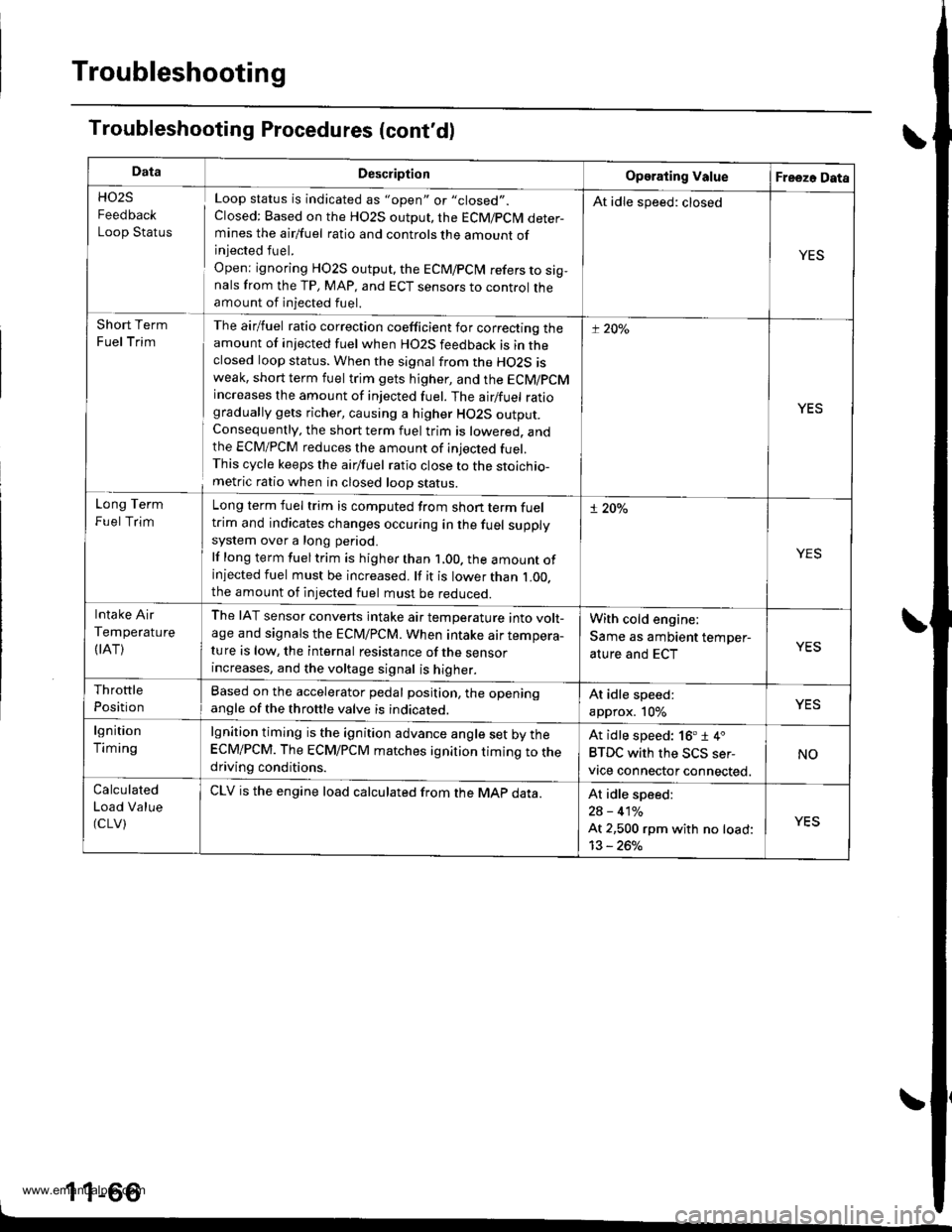
DataDescliptionOperating ValueFreezo Data
HO2S
Feedback
Loop Status
Loop status is indicated as "open" or "closed".
Closed: Based on the HO2S output, the ECM/pCM deter-mines the airlfuel ratio and controls the amount ofinjected fuel.
Open: ignoring HO2S output, the ECM/pCiM refers to sig,nals from the TP, MAP, and ECT sensors to control theamount of injected fuel.
At idle speed: closed
YES
Short Term
Fuel Trim
The airlfuel ratio correction coefficient for correcting theamount of injected fuel when HO2S feedback is in theclosed loop status. When the signal from the HO2S isweak, short term fuel trim gets higher, and the ECM/PCMincreases the amount of injected fuel. The airlfuel ratiogradually gets richer, causing a higher HO2S output.Consequently. the short term fuel trim is lowered. andthe ECM/PCM reduces the amount of injected fuel.This cycle keeps the airfuel ratio close to the stoichio-metric ratio when in closed looD status.
t:20y"
YES
Long Term
Fuel Trim
Long term fuel trim is computed from shon term fueltrim and indicates changes occuring in the fuel supplysystem over a long period.
lf long term fuel trim is higher than 1,00. the amount ofinjected fuel must be increased. lf it is lower than L00.the amount of injected fuel must be reduced.
! 20%
Intake Air
Temperature
(IAT)
The IAT sensor converts intake air temperature into volt-age and signals the ECrU/PCM. When intake air tempera-ture is low, the internal resistance of the sensorincreases, and the voltage signal is higher.
With cold engine:
Same as ambient temper-
ature and ECTYES
Throttle
Position
Based on the accelerator pedal position, the openingangle of the throttle valve is indicateo.At idle speed:
approx. 10%
lgnition
Timing
lgnition timing is the ignition advance angle set by theECM/PCM. The ECM/PCM matches ignition timing to thedriving conditions.
At idle speed: 16'1 4.
BTDC with the SCS ser-
vtce connector connected.
NO
Calculated
Load Value(cLV)
CLV is the engine load calculated from the MAp data.At idle speed:
2A - 410/o
At 2,500 rpm with no load:
13 - 260/o
YES
_
1 1_66
www.emanualpro.com
Page 282 of 1395

PGM-FI System
System Description
INPUTS
CKP/TDC/CYP Sensor
CKF Sensor
MAP Sensor
ECT Sensor
IAT Sensor
TP Sensor
Primary HO2S
Secondary H02S
vss
KS*5
BARO Sensor
ELD*6
Starter Signal
ALT FR Signal
Air Conditioning Signal
Ay'T Gear Position Signal*1
Baftery Voltage (lGN.1)
Brake Switch Signal
PSP Switch Signal
Fuel Tank Pressuae Sensor*4. *5
Countershaft Speed Sensor*1
Mainshaft Speed Sensor*r
OVER-DRIVE Switch Signal*s
ENGINE CONTROL MODULE (ECM)/
POWERTRAIN CONTROL MODULE (PCM) OUTPUTS
|iuel 1"j""- Th,rhg ""d Drrafr";-l
Et*-.nt"tdt"cont.orl
to,r*,c;;trffi;]
l.----.---:. .Lrgnrnon |lmrng Lonrror I
Ecir/PcM B*k',p Fr""il]
m;"t-ll-r*'io*l
Fuel Injectors
PGM-Fl Main Relay (Fuel Pump)
MIL
IAC Valve
Ay'C Compressor Clutch Relay
Radiator Fan Relay
Condenser Fan Relay
ALT
tcM
EVAP Purge Control Solenoid
Valve
Primary HO2S Heater
Secondary H02S HeaterEVAP Bypass Solenoid Valve*a *5
EVAP Control Canister Vent Shut
DLC
Lock-up Control Solenoid Valve*l
Shift Control Solenoid Valve*1
Ay'T Clutch Pressure Control
Solenoid Valve*1
D4 Indicator Light'1 *3, *a
D Indicator Light,l *5
OVER-DRIVE OFF Indicator
Lighl*t *:
*1: A/T {3:'97 model'2: M/f +4:'98 model*5: '99 - 00 models"6: USA
PGM-Fl System
The PGM-Fl system on this model is a sequential multiport fuel injection system.
Fuel iniecior Timing and Duration
The ECM/PCM contains memories for the basic discharge durations at various engine speeds and manifold pressure. The
basic discharge duration, after being read out from the memory, is further modified by signals sent from various sensors
to obtain the final discharge duration.
ldle Air Control
ldle Air Control Valve (lAC Valve)
When the engine is cold, the Ay'C compressor is on, the transmission is in gear, the brake pedal is depressed, the P/S load
is high, or the alternator is charging, the ECM/PCM controls current to the IAC Valve to maintain the correct idle speed.
lgnition Timing Control
o The ECM/PCM contains memories for basic ionition timing at various engine speeds and manifold air flow rates.
lgnition timing is also adjusted for engine coolant temperature.
. A knock control system was adopted which sets the ideal ig nition timing for the octane rating of the gasoline used.*s
Other Control Funstions
1. Starting Control
When the engine is started. the ECM/PCM provides a rich mixture by increasing fuel injector duration.
2. Fuel Pump Control
. When the ignition switch is initially turned on (ll). the ECMiPCM suppli€s ground to the PGM-FI main relay that
supplies current to the fuel pump for two seconds to pressurize the fuel system.
. When the engine is running, the ECM/PCM supplies ground to the PGM-FI main relay that supplies current to the
fuel oumo.
. When the engine is not running and the ignition is on, the ECM/PCM cuts ground to the PGM-FI main relay which
cuts current to the fuel pump.
1 1-80
www.emanualpro.com
Page 333 of 1395
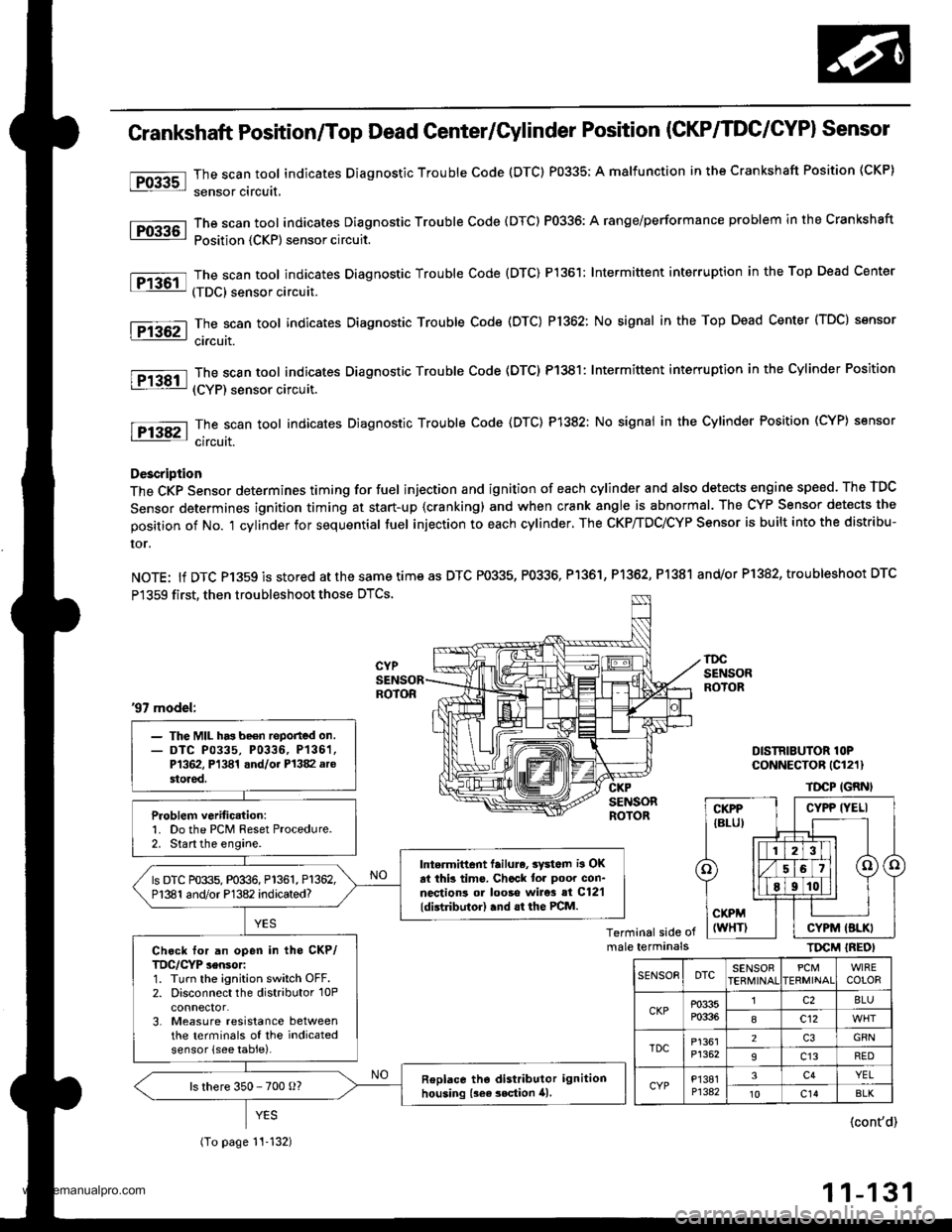
tro-rsl
1Tffi61
tF136t
fPfa6r-1
tF138tl
I-Pi382l
Crankshaft Position/Top Dead Genter/Gylinder Position (CKP/TDC/CYPI Sensor
The scan tool indicates Diagnostic Trouble Code (DTC) P0335; A malfunction in the Crankshaft Position (CKP)
sensor circuit,
The scan tool indicates Diagnostic Trouble Code (DTC) P0336: A range/performance problem in the Crankshaft
Position {CKP) sensor circuit.
The scan tool indicates Diagnostic Trouble Code {DTC) P1361: Intermittent interruption in the Top Dead Center
(TDC) sensor circuit.
The scan tool indicates Diagnostic Trouble Code (DTC) P1362: No signal in the Top Dead Center (TDC) sensor
ci.cuit.
The scan tool indicates Diagnostic Trouble Code (DTC) P1381: Intermittent interruption in the Cylinder Position
(CYP) sensor circuit.
The scan toot indicates Diagnostic Trouble Code {DTC) P1382: No signal in the Cylinder Position (CYP} sensor
circuit.
Description
The CKP Sensor determines timing for fuel injection and ignition of each cylinder and also detects engine speed. The TDC
Sensor determines ignition timing at start-up {cranking) and when crank angle is abnormal. The CYP Sensor detects the
position of No. 't cylinder for sequential fuel injection to each cylinder. The CKP/TDC/CYP Sensor is built into the distribu-
ror.
NOTE: lf DTC P1359 is stored atthesametimeas DTC P0335, P0336, Pl361, P1362, P1381 and/or P1382, troubleshoot DTC
P1359 first, then troubleshoot those DTCS.
DISTRIBUTOR lOPCoNNECTOR (Cl211
TDCP IGRNI
Terminal side ofmale terminalsTIrcM IREOI
'97 model:
- The MIL has be€n reported on.- DTC P0335, P0336, P136'�1,P1362, Pl341 and/oi P1382 arestored.
Problem verific.tion:1. Do the PCM Reset Procedure.2. Start the engine.
Intermittent lailure, 3yd6m i3 OKat thb tims. Chcck tor poor con-nections ol looso wire3 si C12'l
ldistributor) .nd .t the PCM.
ls DTC P0335, P0336, P1361, P1362,P1381 and/or P1382 indicated?
Ch.ck for an open in tho CKP/TDC/CYP sensor:1. Turn the ignition switch OFF.2. Disconnect the distributor 10Pconnector.3. Measure resistance betweenthe terminals of the indicatedsensor (see table).
Replace tho distributor ignitionhousing {sea 3ection 41.ls there 350 - 700 o?
(To page 11-132)
CYPP IYELI
CYPM (BLKI
SENSOEDTCSENSOBPCMERMINAIWIRECOLOR
CKPP0335P0336
lc28LU
8c12
TDCP1361P1352
2GRN
9c13RED
CYPP'�I381P1342
3c4YEL't0c14BLK
{cont'd)
11-131
www.emanualpro.com
Page 371 of 1395
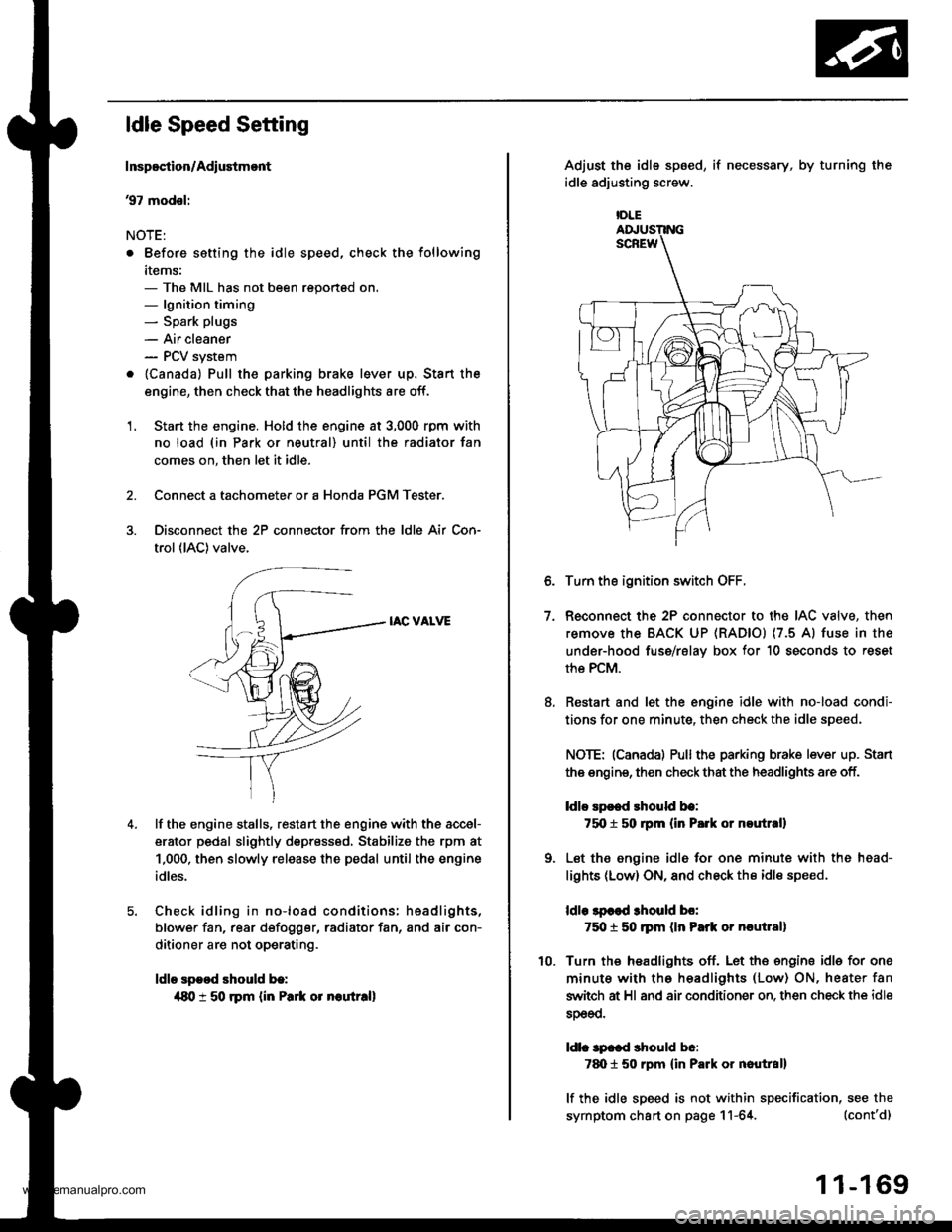
ldle Speed Setting
Inspoction/Adiustmont
37 modsl:
NOTE:
. Before setting the idle speed, check the following
items:- The MIL has not been reportsd on.- lgnition timing- Spark plugs
- Air cleaner- PCV system
. lcanada) Pull the parking brake lever up. Stan the
engine, then check that the headlights are off.
1. Start the engine. Hold the engine at 3,000 rpm with
no load (in Park or neutral) until the radiator fan
comes on, then let it idle.
Connect a tachometer or a Honda PGM Tester.
Disconnect the 2P connector from the ldle Air Con-
trol (lAC) valve.
IAC VALVE
lf the engine stalls, restart the engine with the accel-
erator pedal slightly depr6ss6d, Stabilize the rpm at
1,000, then slowly release the pedal until the engine
idles.
Check idling in no-load conditions: hsadlights,
blower fan, rear d€fogger, radiator fan, and air con-
ditioner are not operating.
ldle spood should b.:
{80 t 50 rpm {in Park or noutr.ll
IDLE
7.
Adjust the idle sp6ed,
idle adjusting screw.
if necessary, by turning the
Turn the ignition switch OFF.
Reconnect the 2P connector to the IAC valve, then
remove the BACK UP (RAD|Ol (7.5 Al fuse in the
under-hood fuse/rslav box for 10 seconds to reset
the PCM.
Restart and let the engine idle with no-load condi-
tions for one minute, then check the idle speed.
NOTE: (Canadal Pullthe parking brake lever up. Stan
the engine, then check that the headlights are off.
ldlo Ep€ed rhould be:
75O t 50 rpm (in P.rk or noutr.ll
Let the engine idl6 for one minute with the head-
lights (Low) ON, and check th€ idl€ speed.
ldle lpcod 3hould bo:
750 t 50 ]pm (in Park or nautlal)
Turn the headlights off. Let th€ engine idle for one
minute with the headlights (Low) ON, heater fan
switch at Hl and air conditioner on. then check the idle
sDeeo.
ldl. specd should b6:
7d) 1 50 rpm {in Park or nautral}
lf the idle speed is not within specification, see the
symptom chart on page 11-64. (cont'd)
1 1-169
www.emanualpro.com
Page 372 of 1395

ldle Control System
ldle Speed Setting (cont'd)
38 - 0O mod6l3:
NOTE: Before setting the idle speed, check the follow-
ing items:- The MIL has not been reported on.- lgnition timing- Spark plugs
- Air cleaner- PCV system
1. Start the engine. Hold the engine at 3.000 rpm with
no load (in Park or neutral) until the radiator fan
comes on, then let it idle.
Connect a tachometer.
Disconnect the IAC valve 2P connector and the EVAP
purge control solenoid valve 2P connector.
CONTROLSOLENOID VALVE
SOLENOID VALVE
lf the engine stalls, restart the engine with the accel-
erato. pedal slightly depressed. Stabilize the rpm at
1,000, then slowly release the pedal until the engine
idles.
Che€k the idle in no-load conditions: headlights, blow-
er fan, rear defogger, radiator fan, and air conditioner
are not operating,
ldle speed should bo:
480 t 50 rpm {in PErk or noutrall
11-170
lf necessary, adjust the idle speed, by turning the
idle adjusting screw.
After adjusting the idle speed, recheck the ignition
timing (see section 4). lf it is out of spec, go back to
steo 4.tDt.E
6. Turn the ignition switch OFF.
7. Reconnect the 2P connectors to the IAC valve and
the EVAP purge control solenoid valve, then do the
ECM/PCM reset procedure.
8. Restart and idle the engine with no-load conditions
for one minute, then check the idle speed.
ldle speod should be:,98 model:
750 t 50 rpm tin Park or neutral)'9!l - 00 modsls:
730 i 50 lpm lin Psrk or neutral)
NOTE: lf the idle speed increases to 780 t 50 rpm(770 1 50 rpml*, this means the EVAP system is
purging the canister. To stop the purging temporari-
ly, raise the engine speed above 1,000 rpm with the
accelerator pedal, then slowly release the pedal.*: '99 - 00 models
9. Let the engine idle for one minute with the head-
lights (Low) ON, and check the idle speed.
ldle speed should be:
38 mod6l:
750 f 50 rpm (in Palk or neutrall'99 - 00 modols:
730 t 50 rpm (in Palk or neutral)
10. Turn the headlights off. Let the engine idle for one
minute with the heater fan switch at Hl and air con-
ditioner on, then check the idle speed.
ldls spqed should be:'98 model:
780 t 50 rpm (in Park or neutrall'99 - 00 mod€ls:
7701 50 rpm lin Park or neutral)
lf the idle speed is not within specification. see the
Symptom Chart on page 11-64.
ADJUSTING
www.emanualpro.com
Page 570 of 1395

PCM Terminal Voltage/Measuring Conditions
A/T Control System -'98 - 00 Models
The PCM terminal voltage and measuring conditions are shown for the connector terminals that are related to the A"/T con-
trol system. The other PCM terminal voltage and measuring conditions are described in section 11.
FCM Connector Terminal Localions
NOTE: 819 and C3 terminalsare applied to'99 - 00 models.
o (16Pt
T6rminal NumberSignalDescriptionMeasuring Conditions/Terminal Voltage
A5CRSDownshift signal input from
cruise control unit
When cruise control is used; Pulsing signal
A10scsTiming and adjustment service
check signal (5 V from PCM)
With ignition switch ON (ll) and service check
connector open:5 V
With ignition switch ON (ll) and service check
connector jumped with special tool: 0 V
A14('98 model)
D4 INDD4 indicator light control
{Voltage from PCM turns D4 light
oN)
When ignition switch is first turned ON (ll):
Battery voltage for two seconds
In E position: Battery voltage
A14
('99 - 00 models)
D INDD indicator light control(Voltage from PCM turns D light
oN)
When ignition switch is first turned ON (ll):
Baftery voltage for two seconds
ln E position: Battery voltage
428ILUInterlock control(Voltage from PCM)
When ignition switch ON {ll), brake pedal
depressed, and accelerator pedal released:
Battery voltage
A.32STOP SWBrake switch signal inputBrake pedal pressed; Battery voltage
Brake pedal released: 0 V
FCM CONNECTOR B I25P}
Terminal NumberSignalDescriptionMeasuring Conditions/Terminal Voltage
B1IGPlPower supply circuit from main
relay via under-hood Fuse 44
With ignition switch ON {ll): Battery voltage
With ignition switch OFF: 0 V
82PG1Ground (G101)
B8LSMLinear solenoid power supply
negative electrode
IG P2Power supply circuit from main
relay
With ignition switch ON (ll): Baftery voltage
With ignition switch OFF: 0 V
810PG2Ground (G101)
B17Linear solenoid power supply
positive electrode
With ignition switch ON (ll): Pulsing signal
819
('99 - 00 models)
O/D INDOver-Drive (O/D) OFF indicator
light control
When ignition switch is first turned ON (ll):
0 V for two seconds
O/D OFF indicator light ON:0 V
O/D OFF indicator light OFF: Battery voltage
s20Ground (G101)
B�21VBUBack-up power supply(under-hood Fuse 47)
Always battery voltage
B�22LG2Ground (G101)
14-54
www.emanualpro.com