misfire HONDA CR-V 1998 RD1-RD3 / 1.G Workshop Manual
[x] Cancel search | Manufacturer: HONDA, Model Year: 1998, Model line: CR-V, Model: HONDA CR-V 1998 RD1-RD3 / 1.GPages: 1395, PDF Size: 35.62 MB
Page 204 of 1395

Fuel and Emissions
Special Tools ...................... 11-2
Component Locations
lndex ...................... ....,.... 11-3
Svstem Description
Vacuum Connections ...........,....,.,................. 1 1-9
Electrical Connections ................................... 1 1-15
System Connectors .,.,,.,............................,.,. 1 1-36
Troubleshooting
Troubleshooting Procedures,.,..................... 11-60
Engine Control Module/Powertrain ConttolModule Terminal Arrangement .............., 11-67
Diagnostic Trouble Code Chart .................... 1 t-75
How to Read Flowcharts .......,.....,.,............... I 1-79
PGM-Fl System
System Description .................,.,.,,,............... 1 1-80
Troubleshooting Flowcharts
Engine Control Module/PowertrainControl Module ........11-52
Manifold Absolute Pressure Sensor ............. 11-90
Intake Air Temperature Sensor .................... 1 1-95
Engine Coolant Temperature Sensor .,..,.,.... 1 1-99
Throttle Position Sensor ...........,.....,.,.,..,...... I 1'103
Primary Heated Orygen Sensor (Sensor 1) ... 11-110
Secondary Heated Oxygen Sensor{Sensor 2l .................. 1 1-117
Heated Oxygen Sensor Heater ..................... 11-121
Fuef Supply System ......11-124
Random Misfire ,....,.,..... 11-126
Mistire Detected in One Cylinder .....-........... 11-128
Knock Sensor ................ 11-130
CKP/TDC/CYP Sensor .................................... 1 1-131
Vehicle Speed Sensor ...............................,.... 1 1-135
Barometric Pressure Sensor .....,...,...,.,,........ 1 1-137
Electrical Load Detector ...,.,.......................... 1 1-138
CKF Sensor ................,.,, '11-112
ECM/PCM lnternaf Circuit ............................. 11'117
HO2S Replacement .,.,.,. 11-148
ldle Control System
System Description ............ 11-149
Troubleshooting Flowcharts
ldle Control System ...... 11-150
fdle Air Control Valve ......................,............. 11-152
Air Conditioning Signal ................................. I 1-155
Alternator FR Signal ...................................... 1 1-159
Starter Switch Si9na1 .................................... t l-161
Power Steering Pressure Switch Signal ...... 11-162
Brake Switch Si9na1 ...................................... 11-166
Fast ldle Thermo Valve .,.,.............................,.,.,. 11-168
ldle speed setting .............. 11-169
Fuel Supply System
Fuel Lines ............................ 11-171
Fuef Tube/Ouick-Conneci Fittings ..................... 11 -175
System Description ............ 11-178
Fuel Pressurg ...................... 11-178
Fuel Iniectors ................,..... 11-179
Fuel Pressure Re9u1ator .............................,.,...., f 1-181
Fuef Fifter ....,.,.,.,,,,.,............11-142
Fuel Pump ........................... 11-183
Fuel Gauge .......................... 11-184
Fuel Gauge Sending Unit ................................... I 1-185
Low Fuel Indicator System ...........,.,..,............... 1 1-185
PGM-FI Main Relay ............. 11-187
Fue|Tank................ ............. 11-191
Intake Air System
System Description ............ 11-193
Air Cleanel ,.,.,..................... 11-194
Throttle Cable ..................... 11-194
Throttle Body........ .............. 11-196
Emission Control System
System D$cription ...,....,.,. 11-199
Tailpipe Emission ............... 11-199
Three Way Catalytic Converter ..................,.,...,, 11-199
Positive Crankcase Ventilation System .,.,,,,.,.., 11-2O1
Evaporative Emission Controls .........,.,.,............ 11-203
www.emanualpro.com
Page 262 of 1395
Troubleshooting
Troubleshooting Procedures
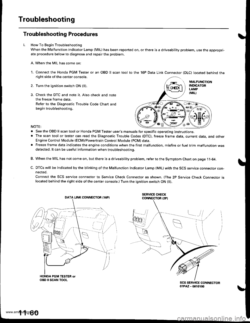
How To Begin Troubleshooting
When the Malfunction indicator Lamp (MlLl has been reported on, or there is a driveability problem, use the appropri-ate procedure below to diagnose and repair the problem.
A. When the MIL has come on:
1. Connect the Honda PGM Tester or an OBD Il scan tool to the 16P Data Link Connector (DLC) located behind theright side of the center console.
Turn the ignition switch ON (ll).
Check the DTC and note it. Also check and note
the freeze frame data.
Refer to the Diagnostic Trouble Code Chart and
begin troubleshooting.
NOTE:
. SeetheOBDll scan tool or Honda PGM Tester user's manuals for specific operating instructions.. The scan tool or tester can read the Diagnostic Trouble Codes (DTC), freeze frame data, current data, and otherEngine Control Module (ECM}/Powertrain Control Module (PCM) data.. Freeze frame data indicates the engine conditions when the first malfunction, misfire or fuel trim malfunction wasdetected. lt can be useful information when troubleshootino.
B. When the MIL has not come on, but there is a driveability problem, refer to the Symptom Chart on page 11-64.
C. DTCs will be indicated by the blinking of the Malfunction Indicator Lamp {MlL) with the SCS service connector con-nected.
Connect the SCS service connector to Service Check Connector as shown. {The 2P Service Check Connecror rslocated behind the right side of the center console.) Turn the ignition switch ON 0l).
DATA LINK CONNECTOR I16PI
1 1-60
www.emanualpro.com
Page 266 of 1395

Troubleshooting
Troubleshooting Procedures (cont'dl
Symptom Chart
Listed below are symptoms and probable causes for problems that DO NOT cause the Malfunction Indicator Lamp (MlL) tocome on. lf the MIL was reported on, go to page 11-60.Troubleshoot each probable cause in the order listed (from left to right) until the symptom is eliminated,The probable cause and troubleshooting page reference can be found below.
Other Probable Causes for an engine that will not start:- Compression- Intake air leakage- Engine locked up- Timing belt- Starting system- Overheating- Battery
SYMPTOMPROBABLE CAUSE
Engine will not sta rt4, 2,3,5,20, 't5, 1
Hard starting2, 4, 12,17, 14, 't9
Cold fast idle too low7, a,9, 6, 17
Cold fast idle too high7,8,9,11,10
ldle speed fluctuates9,7,8, 't1, 10
Misfire or rough runningTroubleshoot for misfire on pages '11-126, 1|21LOl/\/ power2, 10,11, 13, '17, 18,20
Engine stalls2, 4, 12,1,20,9,5, 't6
Probable Cause List (For the DTC Ch8rt, see page ll-75.)
Probable CausePageSystem
Engine controt ruoaute (ecvtffi'I11-42
I 1-178Fuel oressure
PGM-Fl main relav
lgnition system
Crankshatt Position/Top Dead Center/Cylinder position sensor circuit
Intake Air Temperature (lAT) sensor ctrculr
ldle Air Control (lAC) Vatve
Fast idle thermo valve
ldle speed adjustment
Throttle body
Throftle cable
Manifold Absolute P."""rr"ffi
Throftle Position (TP) sensor
Barometric pressur" (gnno-
Ay'T gear position signal
Brake switch signal
Air Cleaner
Three Way Catalytic Converter (TWC)
Evaporative emission (EVAP) control
Contaminated fuel
1 1- 187
Section 4
5't1-'t31,146
6I '�t-95
711-152
81'l-168
1 1- 169
1011-196'1111-'194
12'1 'l -90
1 1- 103
1411-137
15Section 14
161 1- 166
17r 1-194
181 1,199'1911-203
20
11-64
www.emanualpro.com
Page 278 of 1395
Troubleshooting
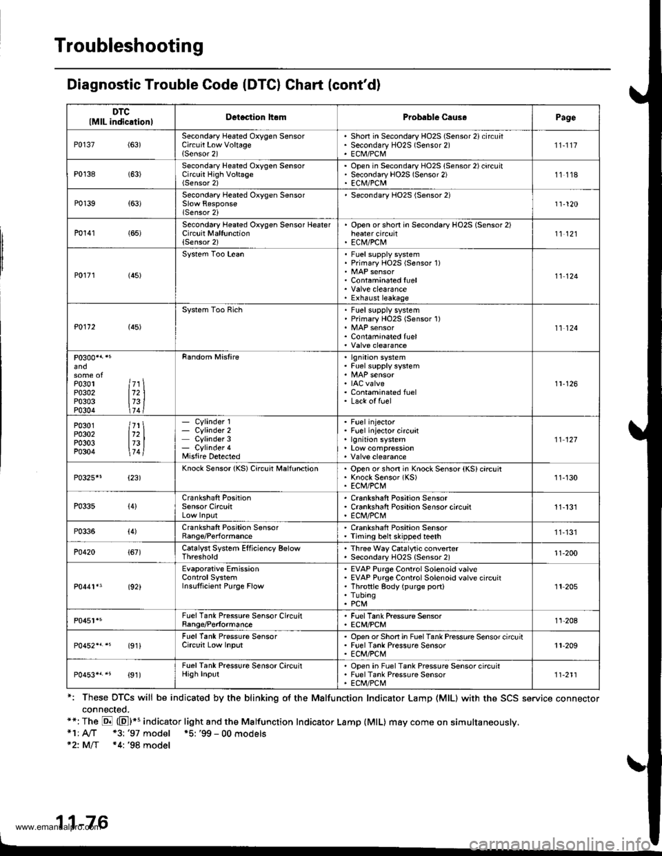
Diagnostic Trouble Code (DTCI Chart (cont'd)
*: These DTCS will be indicated by the blinking o{ the Malfunction Indicator Lamp (MlL) with the SCS service connector
connected.**: The E (El*s indicator light and the Malfunction Indicator Lamp {MlL) may come on simultaneously,*1; A/T *3: '97 model *5: '99 - 00 models*2: MlT *4: '98 model
11-76
DTClMlL indicationlDetection hemProbable Caus.Page
P0137(63)Secondary Heated Oxygen SensorCircuit Low Voltage{Sensor 2)
Shon in Secondary HO2S (Sensor 2) circuatSecondary HO2S (Sensor 2)ECM/PCM
'n-1t7
P0138 (63)Secondary Heated Oxygen SensorCircuit High VoltageOpen in Secondary HO2S (Sensor 2) circuitSecondary HO2S (Sensor 2)EC|\il/PCM11118
P0139{63)Secondary Heated Oxygen Sensor
lSensor 2i
Secondary HO2S (Sensor 2)11-120
P0141 (65)Second6ry Heated Oxygen Sensor HeaterCircuit Malfunction(Sensor 2)
Open orshon in Secondary HO2S (Sensor 2)heater circuitEC|V/PCtu11't2l
P0r71 (45)
System Too LeanFuel supply systemPrimary HOzS (Sensor 1)
Contaminated fuel
Exhaust leakage
11124
P0112 (45)
System Too RichFuel supplv systemPrimary HO2S (Sensor 1)
Contaminated fuel11 124
and
Po3ol ltr \P0302 112 |P0303 173 iP0304 \74 t
Random Mistirelgnition systemFuel supply system
IAC valveContaminated fuelLack of fuel
11-126
P0301 /71 \P0302 112 |P0303 173 |P0304 \7 4l
- Cylinder 1- Cylinder 2Cylinder 3- Cylinder 4Misfire Detected
Fuel injectorFuel injector circuitlgnition system't't 127
P0325*5{23)Knock Sensor {KS) Circuit MalfunctionOpen or shon in Knock Sensor (KS) circuitKnock Sensor (KS)ECM/PCt\411-130
P033s{4}Crankshaft PositionSensor CircuitCrankshaft Position SensorCrankshaft Positaon Sensor circuitE Cl\,l/PC l\,'!11-131
P0336(4)Crankshaft Position SensorRange/PerformanceCrankshaft Position SensorTiming belt skipped teeth11,131
P0420{67)Catalyst System Efficiency BelowThresholdThree Way Catalytic convenerSecondary HO2S {Sensor 2)'t1-200
P0441*3 (92)
Evaporative EmissionControlSystemInsulficient Purge Flow
EVAP Purge Control Solenoid valveEVAP Purge Control Solenoid valve circuitThrottle gody (purge port)TubingPCM
'It 205
P0451*5FuelTank Pressure Sensor CircuitBange/PerformanceFuel Tank Pressure SensorECM/PCMt't-208
(91iFuel Tank Pressure SensorCirclit Low InputOpsn orShort in FuelTank Pressure Sensor circuitFuel Tank Pressure SensorECM/PCt\411-209
P0453*r.5 {91)FuelTank Pressure Sensor CircuitHigh InputOpen in Fuel Tank Pressure Sensor circuitFuel Tank Pressure SensorECt /PCt\.111-211
www.emanualpro.com
Page 328 of 1395
PGM-FI System
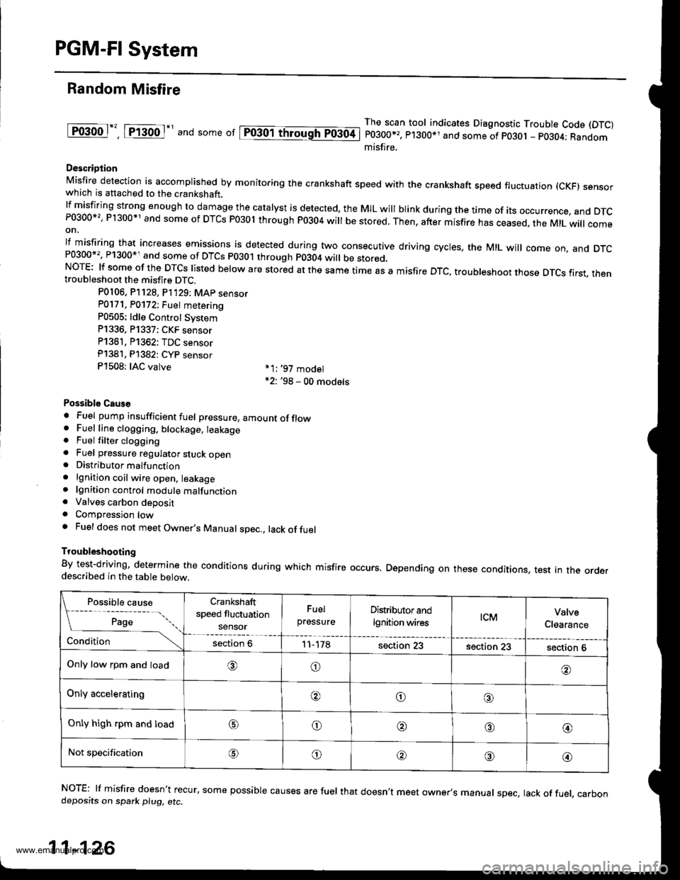
Random Misfire
lF()gool", tftod-' and some or lpiogol throughTo3oti
The scan tool indicates Diagnostic Trouble Code (DTC)
P0300*,, P1300*1 and some of po30t - pO3O4; Randommisfire.
Descriotion
Misfire detection is accomplished by monitoring the crankshaft speed with the crankshaft speed fluctuation (cKF) sensorwhich is attached to the crankshaft.lfmisfiring strong enough to damage the catalyst is detected, the MIL will blink during the time of its occurrence, and DTcP0300*'�, P1300*1 and some of DTCs P03ol through P0304 will be stored. Then, after misfire has ceased, the MtL will comeon,
lf misfiring that increases emissions is detected during two consecutive driving cycles, the MIL will come on, and DTcand some of DTCS p0301 through p0304 wi
be stored.NOTE: lf some of the DTCS listed below are stored at the same time as a misfire DTc, troubleshoot those DTcs first. thentroubleshoot the misfire DTC.
P0106, P]128, P1'129; MAp sensorP0171. P0172; Fuet metering
P0505: ldle Control Svstem
P1336, P1337; CKF sensor
P1361, P1362: TDC sensor
Pl381. Pl382: CYP sensor
P1508: IAC valve *1:,97 model*2: '98 - 00 models
Possiblo Caus€
. Fuel pump insufficient fuel pressure, amountofflow. Fuel line clogging. blockage, leakage. Fuel filter clogginga Fuel pressure regulator stuck open. Distributormalfunction
. lgnition coil wire open, leakage. lgnition control module malfunction. Valves carbon deposita Compression lowa Fuel does not meet Owner's Manual spec., lack offuel
Troubleshooting
By test-driving, determine the conditions during which misfire occurs. Depending on these conditions, test in the orderdescribed in the table below.
Possible cause
[ ;;;;- -....
Crankshaft
speed fluctuation
sensor
Fuel
pressureDistributor and
lgnition wirestcMValve
Clearance
Conditionsection 611-178section 23section 23section 6
Only low rpm and load,6)o
Only acceleratingooo
Only high rpm and loado@,a'@
Not specificationG\o@o@
NOTE: lf misfire doesn't recur, some possible causes are fuel that doesn't meet owner's manual spec, lack of fuel, carbondeposits on spark plu9, etc.
11-126
www.emanualpro.com
Page 329 of 1395
![HONDA CR-V 1998 RD1-RD3 / 1.G Workshop Manual
Misfire Detected in One Cylinder
Ipffi1] Thescantoot indicates Diagnostic Trouble Code (DTC) P0301: Cylinder 1 misfire detected.
lF03O2l 16".""n toot indicates Diagnostic Trouble Code (DTC) P0302; Cy HONDA CR-V 1998 RD1-RD3 / 1.G Workshop Manual
Misfire Detected in One Cylinder
Ipffi1] Thescantoot indicates Diagnostic Trouble Code (DTC) P0301: Cylinder 1 misfire detected.
lF03O2l 16".""n toot indicates Diagnostic Trouble Code (DTC) P0302; Cy](/img/13/5778/w960_5778-328.png)
Misfire Detected in One Cylinder
Ipffi1] Thescantoot indicates Diagnostic Trouble Code (DTC) P0301: Cylinder 1 misfire detected.
lF03O2l 16".""n toot indicates Diagnostic Trouble Code (DTC) P0302; Cylinder 2 misfire detected.
I P0303 | fne scan tool indicates Diagnostic Trouble Code (DTC) P0303: Cylinder3 misfire detected.
lF0il04l 16" ""un tool indicates Diagnostic Trouble Code (DTC) PO3O4: Cylinder 4 misfire detected
Description
Misfire detection is accomplished by monitoring the crankshaft speed with the crankshaft speed fluctuation (CKF) sensor
which is attached to the crankshaft.
lf misiiring strong enough to damage the catalyst is detected, the MIL will blink during the time of its occurrence. and DTC
P0301, P0302, P0303 and/or P0304 will be stored. Then, after the misfire has ceased, the MIL will come on.
lf misfiring that increases emissions is detected during two consecutive driving cycles. the MIL will come on, and DTc
P0301, P0302, P0303 and/or P0304 will be stored.
NOTE: lJ some of the DTcs listed below are stored at the same time as a misfire DTc, troubleshoot those DTcs first, then
troubleshoot the misfire DTC.
P0107, P0108, P'n2a, P1129t MAP sensor
Po'17 'l , P0112t Fuel suPP|Y system
P0441: EVAP insufficient Purge flow
P1336, P1337: CKF sensor
P1359, Pl361, P1362: TDC sensor
Pl381, P1382: CYP sensor
Possible Cause
. Fuel injector clogging, fuel leakage, air leakage
. Fuel injector circuit open or shorted
. Spark plug carbon deposits, fouling, malfunction
. lgnition wires open, leaking
. Distributor malfunction
. Compression low
. Valve clearance out of specification
(cont'd)
11-127
www.emanualpro.com
Page 330 of 1395
PGM-FI System
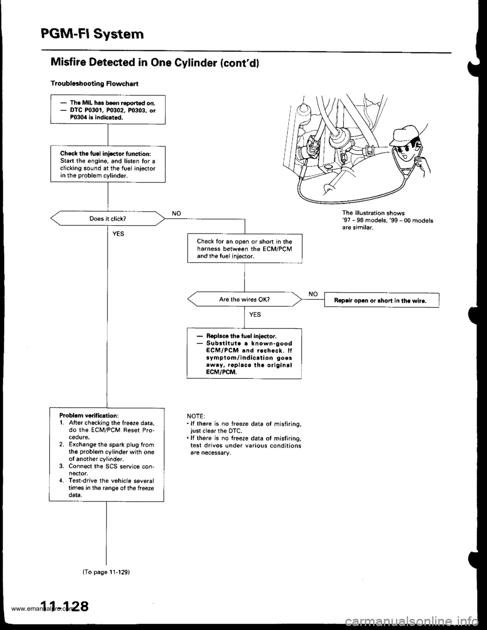
Misfire Detested in One Cylinder (cont'dl
Troubl93hooting Flowchart
The illu stration shows'97 - 98 models,'99 - 00 modelsare similar.
NOTE:.lf there is no freeze data ol misfiring,just clear the DTC..lf there is no freeze data ot misfiring,test drives under various conditionsare necessary,
- Th. MIL h!3 b6on r.portod on.- DTC m30r, P0302, m303. orP0304 is indicated.
Ch.ck tho fuol inicctor tunction:Start the engino, and listen for Iclicking sound at the fuol injectorin the probl€m cylinder.
Check for an open or short in theharness between the ECM/PCMand the luel injector.
Boprir opan or 3hort in tha wlre.
- Roplaco th. tuel inioctor.- Substitut. . known-goodECM/PCM .nd rochock. It3ym ptom/ indicati on go.3aw.y, replace the oliginalECM/PCM.
Problom vorification:1. Atter chacking the lre€ze data,do the ECM/PCM Reset Pro-cedure.2. Exchange the spark plug fromthe problem cylinder with oneol another cylinder.3. Connect the SCS service con-nector.4. Tost-drive the vohicle severaltimes in the rango ol the freezedata.
(To page'11-129)
11-128
www.emanualpro.com
Page 331 of 1395
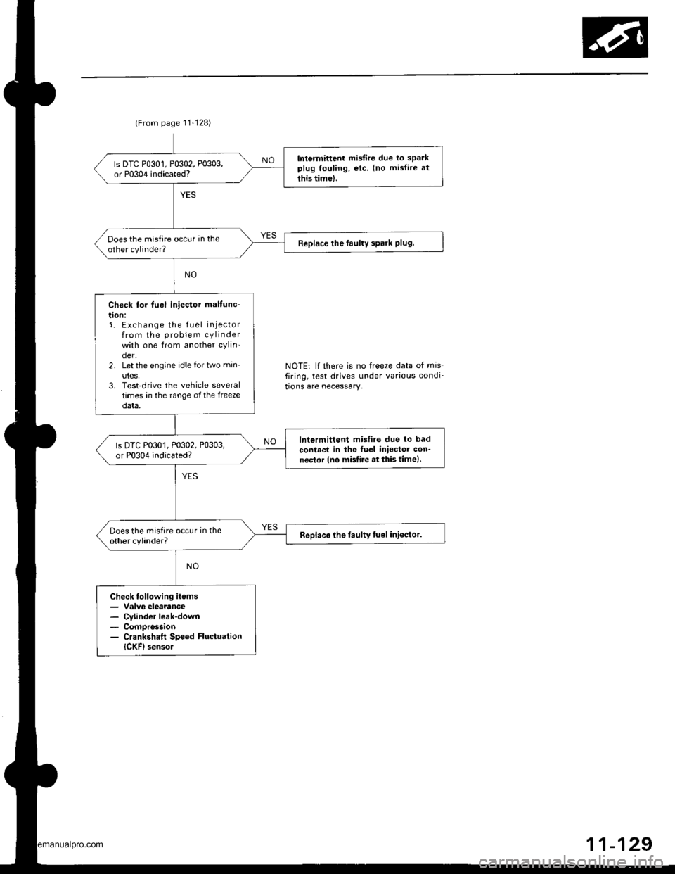
(From page 11-128)
lntormittent misfire due lo sparkplug fouling, etc. (no mislire at
this tim€).
ls DTC P0301, P0302, P0303,or P0304 indicated?
ooes the misfire occur in theother cylinder?Replace the faulty spark Plug.
Check lor fuel iniector maltunc-
t|on:1. Exchange the fuel injectorfrom the problem cylinderwith one from another cylin-der.2. Let the engine idle for two min
utes.3. Test'drive the vehicle severaltimes in the range of the freezedata,
lntermittent misfiro due lo bad
contrct in the fuel iniector con-nector {no misfire at this time).
ls DTC P0301, P0302, P0303,or P0304 indicated?
Does the misfire occur in theother cylinder?Replace lhe faulty luel inlector.
Check following items- Valvo clearance- Cvlinder l€ak-down- Compression- Crsnkshaft Speed FluctuationICKF) sensol
NOTE: lf there is no freeze data of misfiring, test drives under various condi_
tions are necessary.
11-129
www.emanualpro.com
Page 344 of 1395
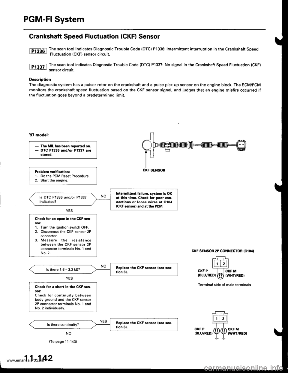
PGM-FI System
Grankshaft Speed Fluctuation (CKF) Sensor
fF13361l Tj":""l.tool indicates Diagnostic Trouble Code (DTCI P1336: Intermittent interruption inthe Crankshaft Speed: Fluctuation (CKF) sensor circuit.
The scan tool indicates Diagnostic Trouble Code (DTC) P1337: No signal in the Crankshaft Speed Fluctuation (CKF)
sensor circuit.
Description
The diagnostic system has a pulser rotor on the crankshaft and a pulse pick-up sensor on the engine block. The ECM/PCM
monitors the crankshaft speed fluctuation based on the CKF sensor signal, and judges that an engine misfire occurred if
the fluctuation goes beyond a predetermined limit.
37 mod.l:
CKF SENSOR 2P CONNECTOR IClO4I
T:]l-r'r Lll
l1 zLl''''CKF P I lcKF Mtalu/aeot fdJ twxrneor\-7
Terminal side of male terminals
(To page 11-113)
11-142
- Tho MIL ha3 been reported on.- DTC P1336 and/or P1337 arestored.
Problem verificrtion:1. Do the PCM Reset Procedure.2. Start the engine.
Intermittent {ailure, systom is OK.l thia timo. Ch6ck tor poor con-nections or loose wir$ at ClorlICKF sonsorl .nd at tho PCM.
Chock tor an opon in th6 CKF .en'30r:1. Turn the ignition switch OFF.2. Disconnect the CKF sensor 2Pconnector,3, M easure the resistancebetween the CKF sensor 2Pconnector terminals No. 'l andNo.2.
ls there 1.6-3.2 kO?
Check fo. a short in the CKF 3en-sot:Check for continuity betweenbody ground and the CKF sensor2P connector terminals No. 1 andNo.2 individually.
CKF SENSOR
www.emanualpro.com