oil. HONDA CR-V 1998 RD1-RD3 / 1.G Workshop Manual
[x] Cancel search | Manufacturer: HONDA, Model Year: 1998, Model line: CR-V, Model: HONDA CR-V 1998 RD1-RD3 / 1.GPages: 1395, PDF Size: 35.62 MB
Page 41 of 1395

Lubrication Points
For the details of lubrication points and type of lubricants to be applied. refer to the illustrated index and various work pro-
cedures (such as Assembly/Reassembly, Replacement, Overhaul, Installation, etc.) contained in each section.
Recomm6nded Engine OilEngine oil viscosity for ambient temperature ranges
100'F
-30 -20 .10 0 10 20 30 40'c
r1: Always use Genuine Honda Manual Transmission Fluid {MTF). Using motor oil can cause stiffer shifting because it
does not contain the orooer additives.*2: Always use Genuine Honda Premium Formula Automatic Transmission Fluid (ATF). Using a non-Honda ATF can affect
shift qualitv.+3r Always use Genuine Honda DOT 3 Brake Fluid. Using a non-Honda brake fluid can cause corrosion and decrease the
life of the system.*4: Always use Genuine Honda Power Steering Fluid. Using any other type of power steering fluid or automatic transmis-
sion fluid can caused increased wear and poor steering in cold weather.
API SERVICE LABEL
/,.*-G\
/.'z-\e\t/6AE\ll-;-1 5w-30 /---l
w
API CERTIFICATION SEAL
ffi-20 0 20
NO.LUBRICATION POINTSLUBRICANT
EngineAPI Service Grade: Use SJ "Energy Conserving" grade oil. The oilcontainer may also display the API Certitication seal shownbelow. Make sure it says "For Gasoline Engines." SAE vjscosity:See chart below.
2
TransmissionManualGenuine Honda MTF*1
AutomaticGenuine Honda Premium Formula Automatic Transmission Fluid(ATF)*'
3Rear differentialGenuine Honda CVT Fluid
4Brake line (includes ABS line)Genuine Honda DOT 3 Brake Fluid*3
5Clutch LineBrake fluid DOT 3 or DOT 4*3
6Shift lever pivots (Manual transmission)Grease with molybdenum disultide
1Release fork (Manual transmission)LJrea Grease UM264 P/N 4'1211 - PYs - 305
IPower steering gearboxSteering grease P/N 08733 - B070E
Throttle cable end {Dashboard lower panel holelSilicone grease
10l112
14
Throttle cable end (Throttle link)Brake master cylinder pushrodPedal linkageBattery terminalsFuelfill lidClutch master cylinder pushrod
Multi purpose grease
1617181920
Hood hinges and hood lockTailgate hingesHatch glass hingesDoor hinges, upper and lowerDoor opening detent
Honda White Lithium Grease
21
22
Caliper Piston seal, Dust seal,Caliper pin, PistonShilt cable and select cable {Manual transmission)Silicone grease
23Brake line ioints (Front and rear wheelhouse)Rust preventives
24Power steering systemGenuine Honda Power Steering Fluid-.
25Air conditioning compressorCompressor oil: SP 10 lP/N 38897 - P13 - A0lAH or38899-P13-A01)For Refrigerant: HFC 134a (R,134a)
3-2
www.emanualpro.com
Page 69 of 1395
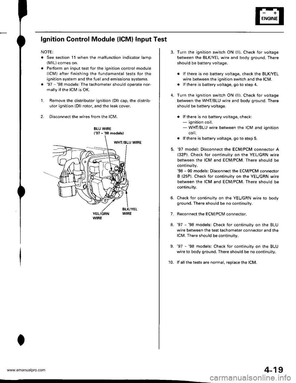
lgnition Control Module (lCMl Input Test
NOTE:
. See section 11 when the malfunction indicator lamp(MlL) comes on.
. Perform an input test for the ignition control module(lCM) after finishing the fundamental tests for the
ignition system and the fuel and emissions systems.
. '97 -'98 models: The tachometer should operate nor-
mally if the ICM is OK.
L Remove the distributor ignition (Dl) cap, the distrib-
utor ignition (Dl) rotor, and the leak cover.
2. Disconnect the wires from the lCM.
8LU WIRE{'97 - '98 models}
4-19
7.
Turn the ignition switch ON {ll). Check for voltage
between the BLK,^/EL wire and body ground. There
should be battery voltage.
. lf there is no battery voltage, check the BLK/rEL
wire betlveen the ignition switch and the lclvl.
. lf there is baftery voltage, go to step 4.
Turn the ignition switch ON (ll). Check for voltage
between the WHT/BLU wire and body ground. There
should be battery voltage.
. lf there is no batteryvoltage, check:- ignition coil.- WHT/BLU wire between the ICM and ignition
corl.
. lf there is battery voltage, go to step 5,
'97 model: Disconnect the ECM/PCM connector A(32P). Check for continuity on the YEL/GRN wire
between the ICM and ECM/PCM. There should be
continuity.'98 - 00 models: Disconnect the ECM,PCM connector
B (25P). Check for continuity on the YEUGRN wire
between the ICM and ECM/PCM. There should be
continuity.
Check for continuity on the YEUGRN wire to body
ground. There should be no continuity.
Reconnect the ECM/PClvl connector.
'97 -'98 models: Check for continuity on the BLU
wire between the test tachometer connector and the
lCM. There should be continuity.
'97 -'98 models: Check for continuity on the BLU
wire to body ground. There should be no continuity.
lf all the tests are normal, replace the lCM.
9.
'10.
www.emanualpro.com
Page 70 of 1395
lgnition System
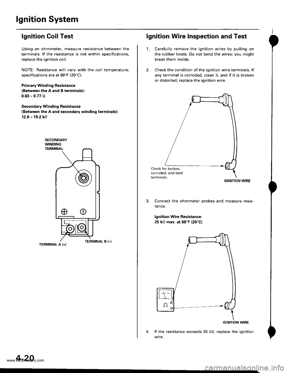
lgnition Coil Test
Using an ohmmeter, measure resistance between the
terminals. lf the resistance is not within sDecifications,
replace the ignition coil.
NOTE: Resistance will vary with the coil temperature;
specifications are at 68"F (20'C).
Plimary Winding Resistance
{Between the A and B terminals):
0.6it - 0.77 0
Secondary Winding Resistance
{Between the A and secondary winding terminals):
12.8 - 19.2 kO
TERMINAL A {+l
4-20
eo
lgnition Wire Inspection and Test
1.Carefully remove the ignition wires by pulling on
the rubber boots. Do not bend the wires; you might
break them inside.
Check the condition of the ignition wire terminals. lf
any terminal is corroded, clean it, and if it is broken
or distorted, replace the ignition wire.
IGNITION WIRE
Connect the ohmmeter probes and measure resis-
tance.
lgnition Wire Resistance:
25 kO max. at 68'F 120'Cl
IGNITION WIRE
4. lf the resistance exceeds 25 kO, replace the ignition
wire.
www.emanualpro.com
Page 103 of 1395
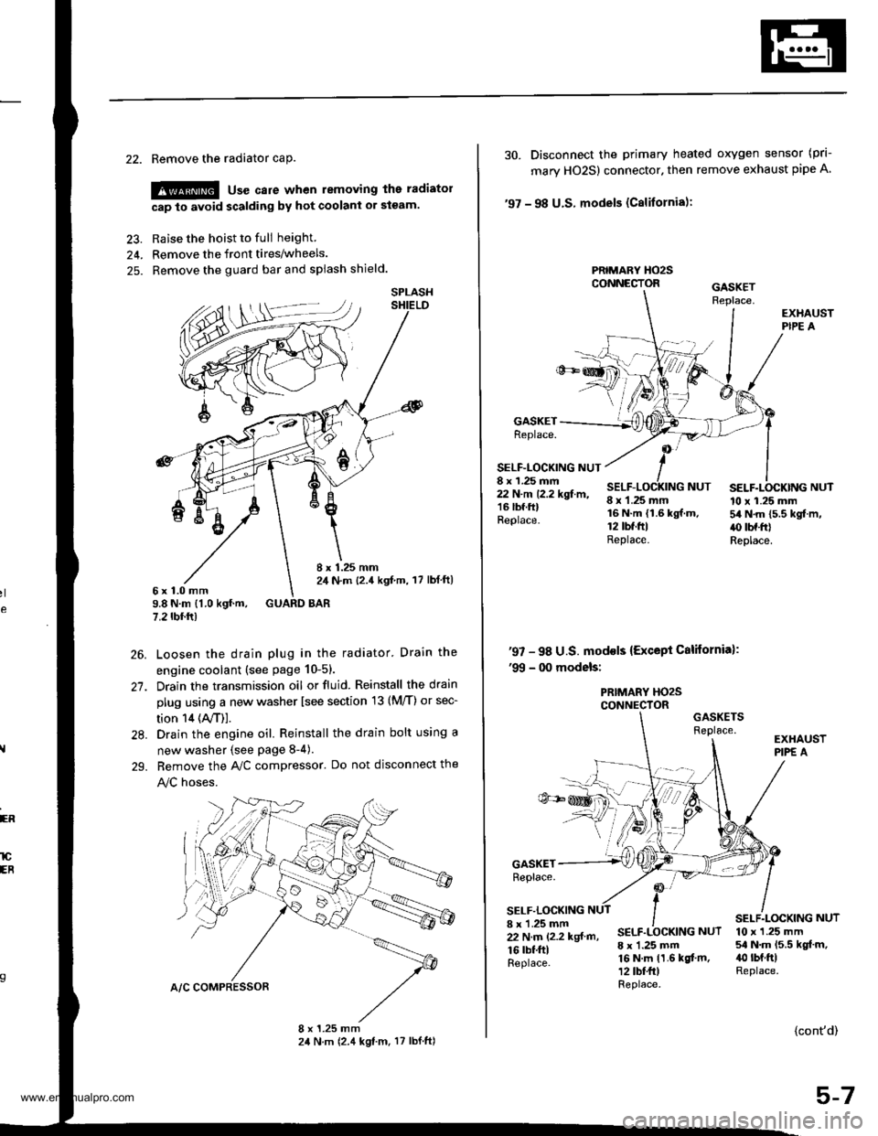
22. Remove the radiator caP.
!@ use care when removing the radiatol
cap to avoid scalding by hot coolani or steam.
23. Raise the hoist to full height
24. Remove the front tires/wheels.
25. Remove the guard bar and splash shield.
8 x 1.25 mm2,1 N.m {2.4 kgf,m, 17 lbl ft)6x1.0mm9.8 N.m {1.0 kgf.m, GUARD BAR7.2 tbf.rr)
Loosen the drain plug in the radiator. Drain the
engine coolant (see page 10-51.
Drain the transmission oil or fluid. Reinstall the drain
plug using a new washer lsee section 13 (M/T) or sec-
tion 14 (ly'T)].
Drain the engine oil. Reinstall the drain bolt using a
new washer {see page 8-4).
Bemove the A,/C compressor. Do not disconnect the
!y'C hoses.
SPLASH
26.
27.
28.
29.
ER
lCEB
30. Disconnect the primary heated oxygen sensor (prl-
mary HO2S) connector. then remove exhaust pipe A
'97 - 98 U.S. models (Cslifornia):
PRIMARY HO2SCONNECTOR
GASKETReplace.
SELF-LOCKING NUT8 x 1.25 mm22 N.m 12.2 kgf.m,16 lbf.ftlReplace.
8 x 1.25 mm16 N.m {1.6 kgf.m.12 tbt.ftlReplace.
SELF.LOCKING NUT10 x 1.25 mm54 N.m 15.5 kgf.m,.() tbf.frlReplace.
NUT
'97 - 98 U.S. mod€ls {Except California):'99 - 00 models:
PRIMARY HO2SCONNECTORGASKETSReplace.
GASKETReplace.
SELF.LOCKING8 x 'l.25 mm22 N.m (2.2 kgf m,
16 rbf.ftlReplace.
SELF.LOCKING NUT
8 x 1.25 mm16 N.m 11.6 kgf.m,12 tbt fr)Replace.
10 x 1.25 mm54 N.m 15.5 kgt.m,40 rbt.ftlReplace.
{cont'd)
5-7
www.emanualpro.com
Page 104 of 1395
Engine RemovaUlnstallation
OOI{TROL PI
Removal (cont'dl
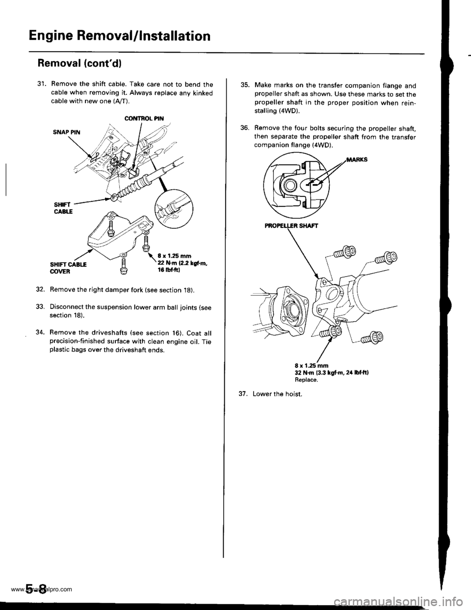
31. Remove the shift cable. Take care not to bend the
cable when removing it. Always replace any kinked
cable with new one (Afl-).
SNAP PIN
sHtFT CABttOOVEB
8 x 1.25 mmt2 N.m 12.2 lgtr'l'',,16 tbf.ftl
Remove the right damper fork (see section 18).
Disconnect the suspension lower arm ball joints (see
section 18),
Remove the driveshafts (see section t6). Coat allprecision-finished surface with clean engine oil. Tieplastic bags over the driveshaft ends.
5-8
34.
Make marks on the transfer companion flange andpropeller shaft as shown. Use these marks to set thepropeller shaft in the proper position when rein-
stalling (4WD).
Remove the four bolts securing the propeller shaft,then separate the propeller shaft from the transfer
companion flange (4WD).
E x 1.25 mm32 N.m 13.3 lgt.m, 24 lbt'ftlRepl€ce.
37. Lower the hoist,
www.emanualpro.com
Page 140 of 1395
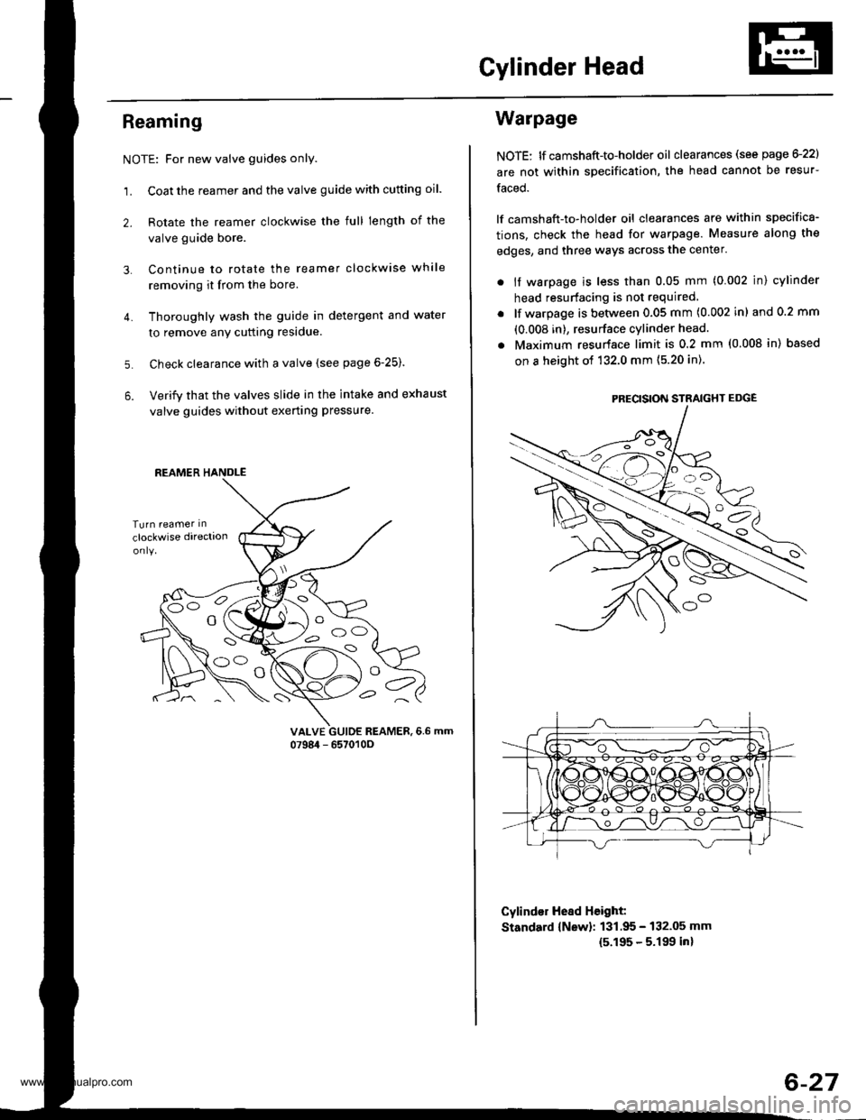
Cylinder Head
Reaming
NOTE: For new valve guides only.
1. Coat the reamer and the valve guide with cutting oil.
2. Rotate the reamer clockwise the full length of the
valve guide bore.
Continue to rotate the reamer clockwise while
removing it from the bore.
Thoroughly wash the guide in detergent and water
to remove anY cutting residue.
Check clearance with a valve (see page 6-25).
Verify that the valves slide in the intake and exhaust
valve guides without exerting pressure.
3.
4.
5.
6.
vALvE GUIDE REAMER,6.6 mm0798i1 - 657010O
REAMER HANDLE
e
Warpage
NOTE: lf camshaft-to-holder oil clearances (see page G22)
are not within specification, the head cannot be resur-
faced.
lf camshaft-to-holder oil clearances are within specifica-
tions, check the head for warpage. Measure along the
edges, and three ways across the center.
. if warpage is less than 0.05 mm (0.002 in) cylinder
head resurfacing is not required
lf warpage is between 0.05 mm (0.002 in) and 0.2 mm
(0.008 in), resurface cylinder head.
Maximum resurface limit is 0.2 mm (0.008 in) based
on a height of 132.0 mm (5.20 in).
Cylind€r Hesd Height:
Standard {New}: 131.95 - 132.05 mm
15.195 - 5.199 inl
PRECISION STRAIGHT EDGE
6-27
www.emanualpro.com
Page 142 of 1395
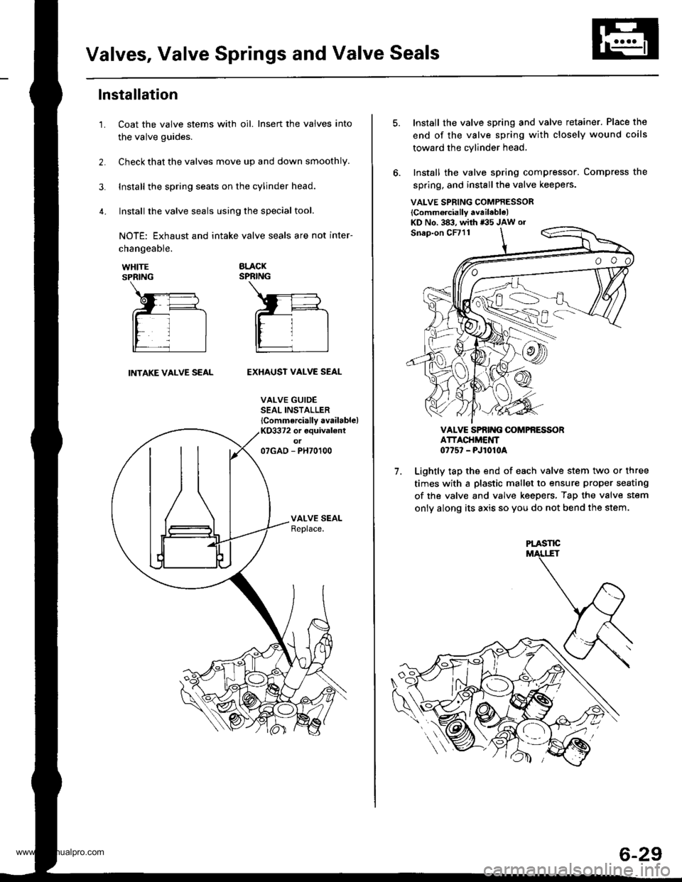
Valves, Valve Springs and Valve Seals
lnstallation
Coat the valve stems with oil. Insert the valves into
the valve guides.
Check that the valves move up and down smoothly.
Install the spring seats on the cylinder head.
Install the valve seals using the special tool.
NOTE: Exhaust and intake valve seals are not inter-
1.
changeable.
WHITESPRING
BLACKSPRING
INTAKE VALVE SEALEXHAUST VALVE SEAL
VALVE GUIDESEAL INSTALLER
lCommercially available)KO3372 or equival€ntot07GAD - PH70100
VALVE SPRING COMPRESSOR
lComm6rcially available)KD No. 383, with *35 JAw or
7.
Install the valve spring and valve retainer. Place the
end of the valve spring with closely wound coils
toward the cylinder head,
Install the valve spring compressor. Compress the
spring, and install the valve keepers.
VALVE SPRIT{G OOMPfi ESSORATTACHMENT0775' - PJ1010A
Lightly tap the end of each valve stem two or three
times with a plastic mallet to ensure proper seating
of the valve and valve keepers, Tap the valve stem
only along its axis so you do not bend the stem.
PLASTE
6-29
www.emanualpro.com
Page 146 of 1395
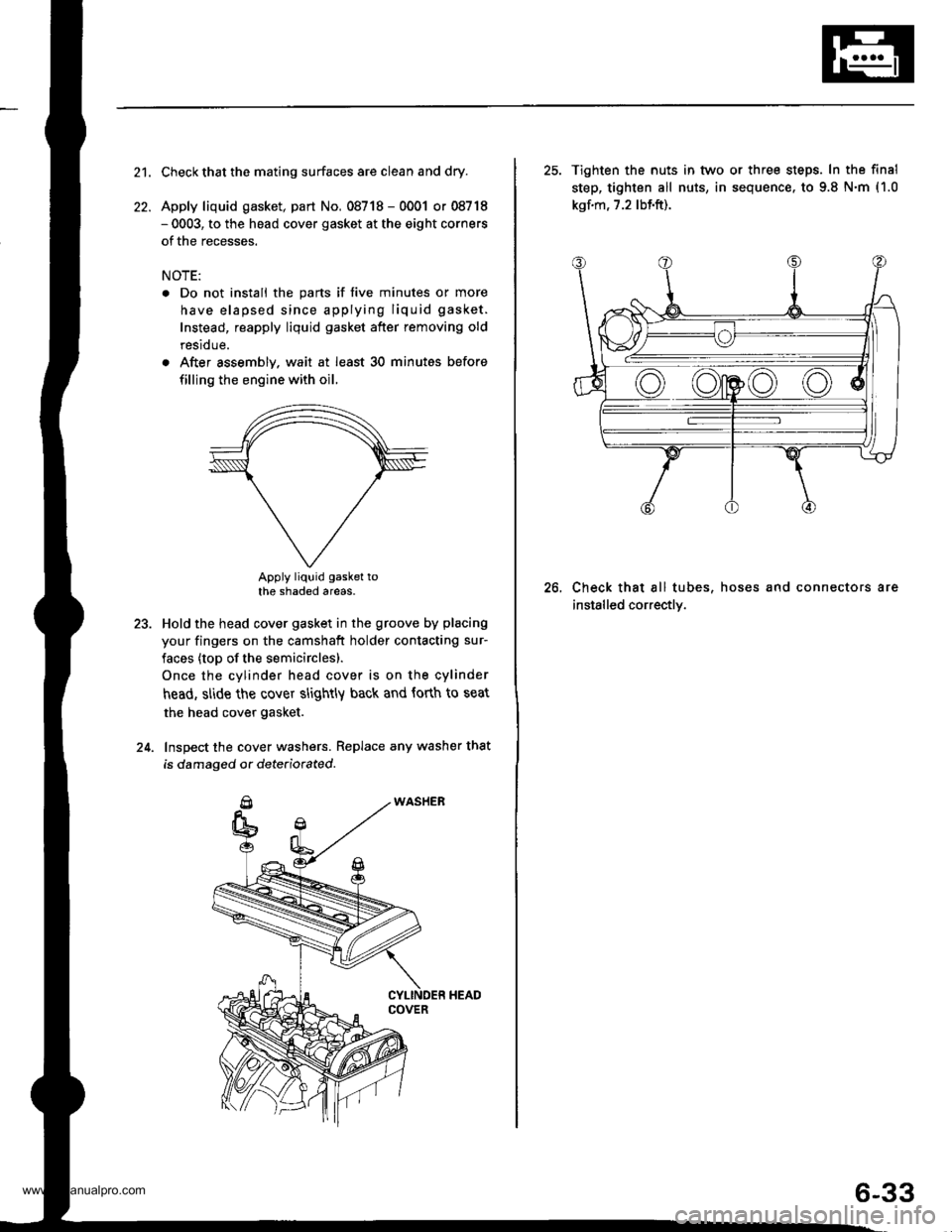
21.
22.
Check that the mating surfaces are clean and dry.
Apply liquid gasket, part No. 08718 - 0001 or 08718- 0003, to the head cover gasket at the eight corners
of the recesses.
NOTE:
. Do not install the parts if five minutes or more
have elapsed since applying liquid gasket.
Instead, reapply liquid gasket after removing old
residue.
. After assembly. wait at least 30 minutes before
filling the engine with oil.
Apply liquid gasket tothe shaded areas.
Hold the head cover gasket in the groove by placing
your fingers on the camshaft holder contacting sur-
faces (top of the semicirclesl.
Once the cylinder head cover is on the cylinder
head, slide the cover slightly back and forth to seat
the head cover gasket.
Inspect the cover washers. Replace any washer that
is damaged or dete(iorated.
23.
24.
25. Tighten the nuts in tvvo or three steps. In the final
step, tighten all nuts, in sequence. to 9.8 N.m (1.0
kgf.m, 7.2 lbf.ft).
Check that all tubes, hoses and connectors are
installed correctly.
26.
6-33
www.emanualpro.com
Page 167 of 1395
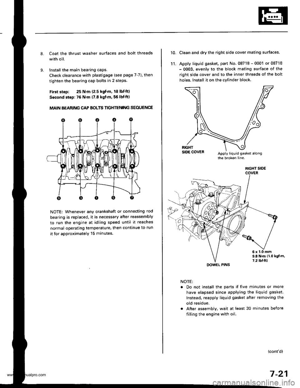
Coat the thrust washer surtaces and bolt threads
with oil.
Installthe main bearing caps.
Check clearance with plastigage (see page 7-7), then
tighten the bearing cap bolts in 2 steps.
First slsp: 25 N.m {2.5 kgf'm, 18 lbf'ft}
Sscond step: 76 N'm (7.8 kgf'm. 56 lbf'ft)
MAIN BEARING CAP BOLTS TIGHTENING SEOUENCE
NOTE: Whenever any crankshaft or connecting rod
bearing is replaced, it is necessary after reassembly
to run the engine at idling speed until it reaches
normal operating temperature, then continue to run
it for approximatelY 15 minutes.
10.Clean and dry the right side cover mating surfaces.
Apply liquid gasket, part No. 08718 - 0001 or 08718
- 0003, evenly to the block mating surface of the
right side cover and to the inner threads of the bolt
holes. Install it on the cylind€r block
11,
6x1.0mm9.E N.m {1.0 kgt m,7.2 tbf.ft)
NOTE:
. Do not install the parts if five minutes or more
have elapsed since applying the liquid gasket.
Instead, reapply liquid gasket after removing the
old residue.
. After assembly, wait at least 30 minutes before
filling the engine with oil.
(cont'dl
7-21
RIGHT SIDE
OOWEL PINS
www.emanualpro.com
Page 174 of 1395
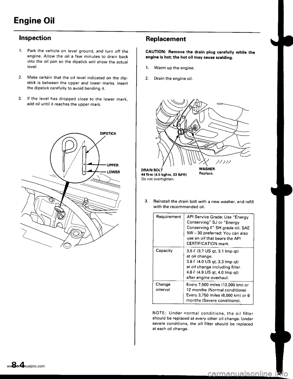
Engine Oil
Inspection
2.
1.Park the vehicle on level ground, and turn off theengine. Allow the oil a few minutes to drain backinto the oil pan so the dipstick will show the actuallevet,
Make certain that the oil level indicated on the dip-stick is between the upper and lower marks. Insertthe dipstick carefully to avoid bending it.
lf the level has dropped close to the lower mark,add oil until it reaches the upper mark.
8-4
Replacement
CAUTION: Remove the drain plug caretuly white theengino is hot; the hot oil may cause scalding.
1. Warm up the engine.
2. Drain the engine oil.
WASHERR€place.ORAIN BOL4il N.m {4.5 kgtm,33 lbf.ft)Do not overtighten.
3. Reinstall the drain bolt with a new washer, and refill
with the recommended oil.
RequirementAPI Service Grade: Use "Energy
Conserving " SJ or "Energy
Conserving ll" SH grade oil. SAE
5W - 30 preferred: You can also
use an oil that bears the API
CERTIFICATION mark.
Capacity3.5 { (3.7 US qt,3.1 lmp qt)
at oil change.
3.8 / (4.0 US qt,3.3 lmp qr)
at oil change including filter.
4.6 { (4.9 US qt, 4.0 lmp qt)
after engine overhaul.
Change
Inlerval
Every 7,500 miles (12,000 km) or12 months (Normal conditions)
Every 3,750 miles (6,000 km) or 6months (Severe conditions).
NOTE: Under normal conditions, the oil filtershould be replaced at every other oil change. Undersevere conditions, the oil filter should be replacedat each oil change.
www.emanualpro.com