line HONDA CR-V 1999 RD1-RD3 / 1.G Workshop Manual
[x] Cancel search | Manufacturer: HONDA, Model Year: 1999, Model line: CR-V, Model: HONDA CR-V 1999 RD1-RD3 / 1.GPages: 1395, PDF Size: 35.62 MB
Page 727 of 1395
Disassembly/Reassembly
1.Remove the ATF guide cap by pushing the sub-shaft
inside the transmission housing.
Remove the 1st-hold clutch assembly by pulling,
then removing the sub-shaft.
Install new O-rings on the sub-shaft.
NOTE: Wrap the shaft splines with tape to prevent
damaging the O-rings.
Place the sub-shaft in the transmission housing,
and install the'lst-hold clutch assembly,
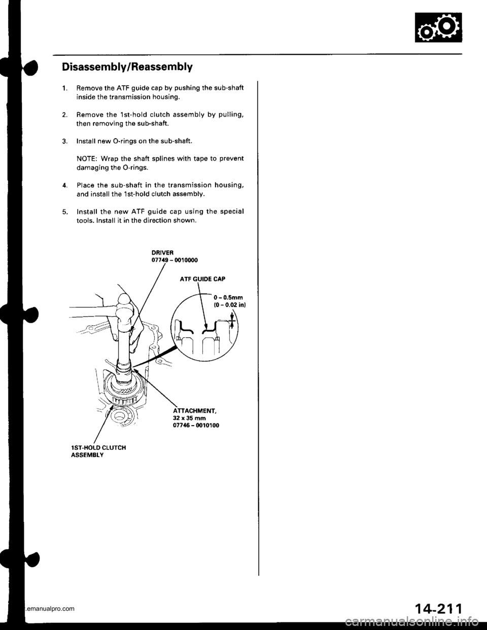
Install the new ATF guide cap using the special
tools. Install it in the direction shown.
ATTACHMENT,32x35mm07746 - 0010t00
14-211
www.emanualpro.com
Page 756 of 1395
Transfer Assembly
Reassembly
NOTE:
. While reassembling the transfer assembly:. Check and adjust the transfer gear tooth contact.. Measure and adjust the transfer gear backlash.. Check and adjust the tapered roller bearing stan-
ing torque.
. Coat all pans with ATF during reassembly.. Replace the tapered roller bearing and the bearing
outer race as a set if either part is replaced.. Replace the transfer drive gear and the transfer dri-ven gear shaft as a set if either part is replaced.
Outline of Assembly
1.Select the 35 mm thrusi shim.
Psrtorm this procedute if the transter driven g€ar
shaft or the tapered roller bearing on the transfer
driven gear shaft is replaced.
Prea$emble the parts to check and adiust transtelgear backlash and transfer gear tooth contact.
Disassemble the parts, then assemble the translerdriven gsar shaft and its related pans.
2.
3.
4. Measure and adjust the starting torque oI the
transfer driven gear shaft tapered roller bearing.
5. Assemble the transfer shaft and its related parts.
6. Measure and adiust the total starting torque.
35 mm Thrust Shim Selection
L Select the 35 mm thrust shim if the transfer drivengear shaft or the tapered roller bearing on the trans-
fer driven gear shaft is replaced.
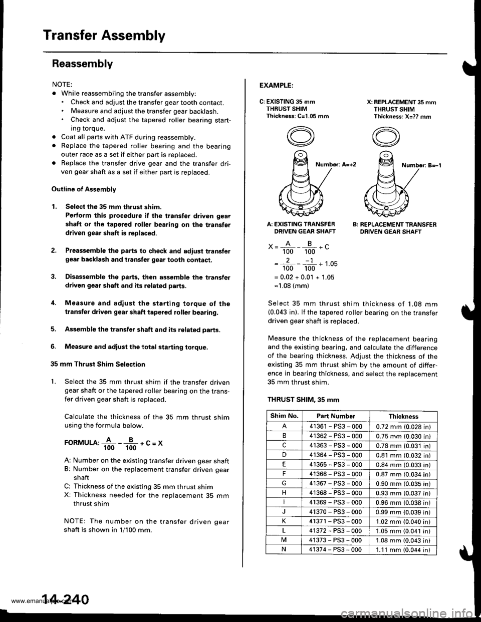
Calculate the thickness of the 35 mm thrust shimusing the formula below.
FoRMULA:+ -*-+c=x
A: Number on the existing transfer driven gear shaft
B; Number on the replacement transfer driven gear
shaft
C: Thickness ofthe existing 35 mm thrust shimX: Thickness needed for the replacement 35 mmthrust shim
NOTE: The number on the transfer driven oear
shaft is shown in 'll100 mm.
14-240
EXAMPLE:
C: EXISTING 35 mmTHRUST SHIMThickness: C=1.05 mm
X: REPLACEMENT 35 mmTHRUST SHIMThickness: X=?? mm
Number: A=+2Numbe.: B=-'l
Ar EXISTING TRANSFERDRIVEN GEAR SHAFT
x= A - B .c" 100 100 -
2-1
100 100 '-
= 0.02 + 0.0'l + 1.05=1.08 {mm)
B: REPLACEMENT TRANSFERDRIVEN GEAR SHAFT
Select 35 mm thrust shim thickness of l�08 mm(0.043 in). lf the tapered roller bearing on the transfer
driven gear shaft is replaced.
Measure the thickness of the replacement bearingand the existing bearing, and calculate the difference
of the bearjng thickness. Adjust the thickness of the
existing 35 mm thrust shim by the amount of differ-
ence in bearing thickness, and select the replacement
35 mm thrust shim.
THRUST SHIM, 35 mm
Shim No.Part NumberThickness
41361 - PS3 - 0000.72 mm (0.028 in)
41362-PS3-0000.75 mm {0.030 in}
c41363-PS3-0000.78 mm (0.03'1 in)
D41364-PS3-0000.81 mm (0.032 in)
41365-PS3-0000.84 mm (0.033 an)
F41366-PS3-0000.87 mm (0.034 in)
41367-PS3-0000.90 mm (0.035 in)
H41368-PS3-0000.93 mm (0.037 in)
41369-PS3-0000.96 mm 10.038 in)
41370-PS3-0000.99 mm (0.039 in)
K4 r371 - PS3 - 0001.02 mm (0.040 in
41372-PS3-0001.05 mm (0.041 in
M41373-PS3-0001.08 mm (0.043 in
N41374-PS3-000'1.11 mm 10.044 in
www.emanualpro.com
Page 771 of 1395
5C.
36.
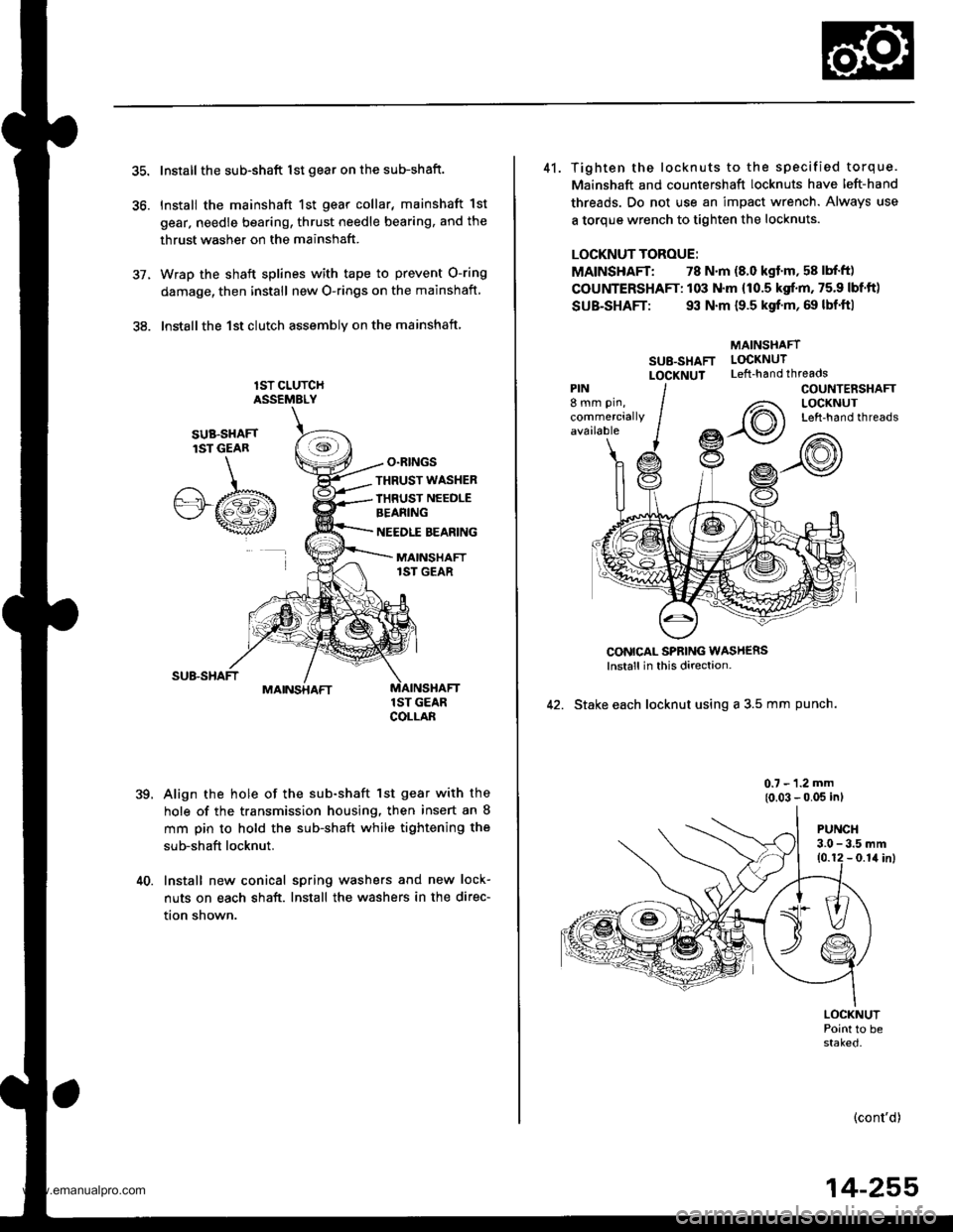
Install the sub-shaft lst gear on the sub-shaft.
Install the mainshaft 1st gear collar, mainshaft 1st
gear, needle bearing, thrust needle bearing, and the
thrust washer on the mainshaft.
Wrap the shaft splines with tape to prevent O-ring
damage, then install new O-rings on the mainshaft
lnstallthe 1st clutch assemblv on the mainshaft
lST CLUTCHASSEMELY
O.RINGS
,te
SUB.SHAFTlST GEAR
.A/.b"'"wt
THRUST WASHER
IHRUST NEEDLEBEANING
NEEDLE BEARING
MAINSHAFT1ST GEAR
MAINSHAFT
39.
1ST GEARCOLLAB
Align the hole of the sub-shaft lst gear with the
hole of the transmission housing, then insert an 8
mm pin to hold the sub-shaft while tightening the
sub-shaft locknut.
40. Install new conical spring washers and new lock-
nuts on each shaft. Install the washers in the direc-
tion shown.
41. Tighten the locknuts to the specified torque.
Mainshaft and countershaft locknuts have left-hand
threads. Do not use an impact wrench. Always use
a torque wrench to tighten the locknuts.
LOCKNUT TOROUE:
MAINSHAFT: 78 N.m (8.0 kgf'm, 58 lbf'ft)
COUNTERSHAFT: 103 N.m (10.5 kgf.m, 75.9 lbf'ft)
SUB-SHAFT: 93 N.m {9.5 kgf'm, 69 lbf'ft|
MAINSHAFT
SU8-SHAFT LOCKNUT
LOCXNUT Left-handthreads
CONICAL SPBING WASH€RSlnstall in this direction-
42. Stake each locknut using a 3.5 mm punch.
0.7 - 1.2 mm
{0.03 - 0.05 inl
PIN8 mm pin,
commerciallyavailable
COUNTENSHAFTLOCKNUTLeft-hand threads
PUNCH3.0 - 3.5 mm10.12 - 0.1il inl
LOCKNUTPoint to bestaked.
(cont'd)
14-255
www.emanualpro.com
Page 773 of 1395
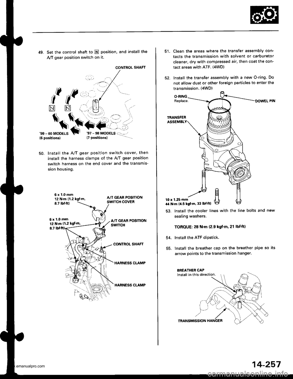
49. Set the control shaft to E position, and install the
A,/T gear position switch on it.
CONTROL SHAFT
l( ((,,, ,.
*
$*\.t+-
NN
6x1.0mm12 N.m 11.2 kgt.m,8.7 tbf.ftl
6xl.0mm12 N.m 11.2 kgf'm,
8,7
'gtt - 00 MoDELS{6 position3}T
Install the A/T gear position switch cover, then
install the harness clamps of the AviT gear position
switch harness on the end cover and the transmis-
sion housing.
50.
CONTROL SHAFT
HARNESS CLAMP
HARNESS CLAMP
Clean the areas where the transfer assembly con-
tacts the transmission with solvent or carburetor
cleaner, dry with compressed air, then coat the con-
tact areas with ATF. (4WD)
Install the transfer assembly with a new O-ring. Do
not allow dust or other foreign particles to enter the
transmission. {4WD)
O.RINGReplace-
10 r 1.25 mma,a N'm 14.5 kgt'm, 33 lbf'ftl
54.
55.
lnstall the cooler lines with the line bolts and new
sealing washers.
TOROUE: 28 N.m 12.9 kgif'm. 21 lbf'ft)
Install the ATF dipstick.
lnstall the breather cap on the breather pipe so its
arrow points to the transmission hanger.
TRANSMISSION
14-257
www.emanualpro.com
Page 776 of 1395
Transmission
Installation (cont'dl
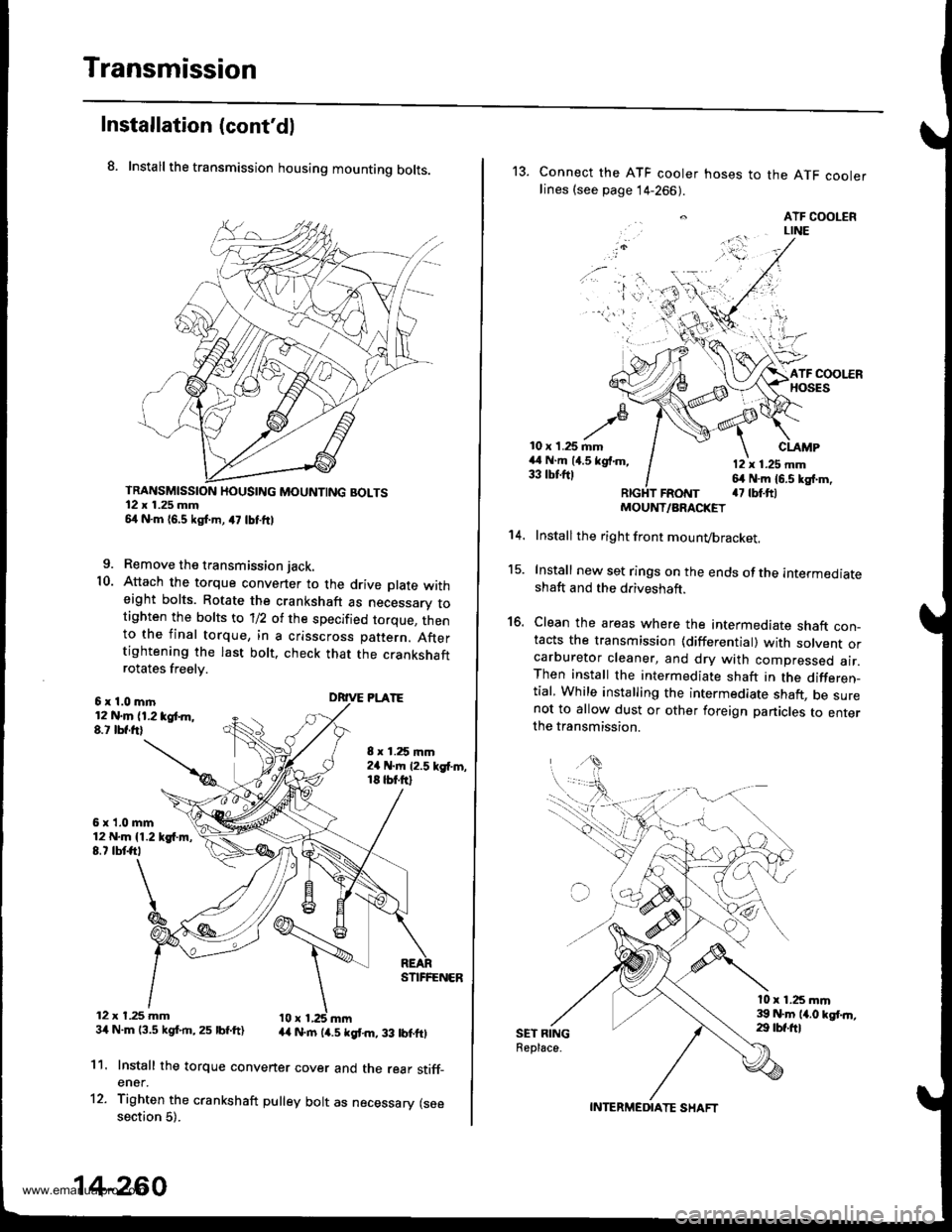
8. Install the transmission housing mounting bolts.
TRANSMISSION HOUSING MOUNTING BOLTS12 x 1.25 mm54 N.m 16,5 kgf.m, a7 lbtftl
9. Remove the transmission jack.
10. Attach the torque convener to the drive plate witheight bolts. Rotate the crankshaft as necessarv totighten the bolts to 'll2 of the specified torque, thento the final torque, in a crisscross pattern. Aftertightening the last bolt. check that the crankshaftrotates freelv.
6x1.0mln12 N.m (1.2 tgt m,8.t lbf.frl
6x1.0mm12 N.m {1.219{.m,8.7 tbtft,
12 x t.25 mm34 N.m 13.5 kgf.rn,25 lbf.ft)
8 x 1.25 mm2a N.m 12.5 kgf'm,18 tbt.ftl
DRIVE PLATE
STIFFENER
44 N.rn (4.5 kgt m, 33 lbtftl
11.
12.
Install the torque convener cover and the rear stiff_ener.
Tighten the crankshaft pulley bolt as necessary (seesection 5).
14-260
13. Connect the ATF cooler hoses to the ATF coolerlines (see page 14-266).
. ATF COOLERLINE
'i 'l'r',:,.) -
10 x 1.25 mm44 N.m (4.5 kgf.m,33 tbtftl
CLAMP
12 x 1.25 mm64 N.m 16.5 kg{.m,a7 tbt.ftlFRotrtT
15.
16.
't 4.
SET RINGReplace.
MOUNT/ARACKET
Install the right front mounvbracket.
Install new set rings on the ends of the intermediateshaft and the driveshaft.
Clean the areas where the intermediate shaft con_tacts the transmission {differential) with solvent orcarburetor cleaner, and dry with compressed air.Then install the intermediate shaft in the differen_tial, While installing the intermediate shaft, be surenot to allow dust or other foreign panicles to enterthe transmission.
l0 x 1.25 mm39 N.m 14.0 kgt.n,29 tbf.ftl
INTERMEDIATE SHAFT
www.emanualpro.com
Page 778 of 1395
Transmission
Installation (cont'dl
2WD:
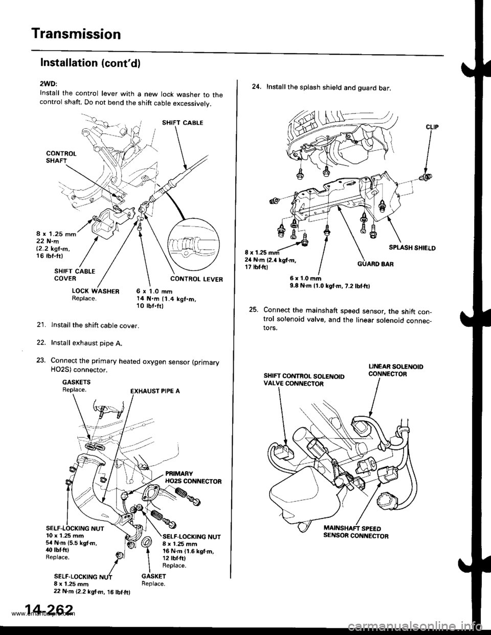
Install the control lever with a new lock washer to thecontrol shaft. Do not bend the shift cable excessivelv.
8 r 1.25 mm22 N.m|'2.2 kgt.m,16 rbf.ft)
SI{IFT CAELECOVER
LOCK WASHER 6 x 1.0 mmReplace. 14 N.m 11.4 kgt.m,10 tbr.frl
lnstallthe shift cable cover.
Install exhaust pipe A.
Connect the primary heated orygen sensor (primary
HO2S) connector.
GASKETSReplace.
22.
23.
10 x 1.25 m.n5r N.m {5.5 kgf.m,40 tbtftlReplace.
SELF.LOCKING
SELF-LOCKING NUT8 ! 1.25 mm16 N.m {1.6 kgf.m,12 lbf.fttReplace.
8 x 1.25 mm22 N.m {2,2 kgt.m, l5 lbt.ftl
SHIFT CABLE
14-262
24. Installthe splash shield and guard bar,
8 x 1.2524 N.m {2.a kgl.m,17 tbt.ftl
SPLASH SHIELD
GUARO BAR
25.
6r1.0|r|m9.8 N.m l1.0lgf.m, 7.2 tbtftl
Connect the mainshaft speed sensor, the shift con-trol solenoid valve, and the linear solenoid connec_tors,
SHIFT CONTROL SOLENOIDVALVE CONNECTOR
www.emanualpro.com
Page 780 of 1395
Transmission
Cooler Flushing
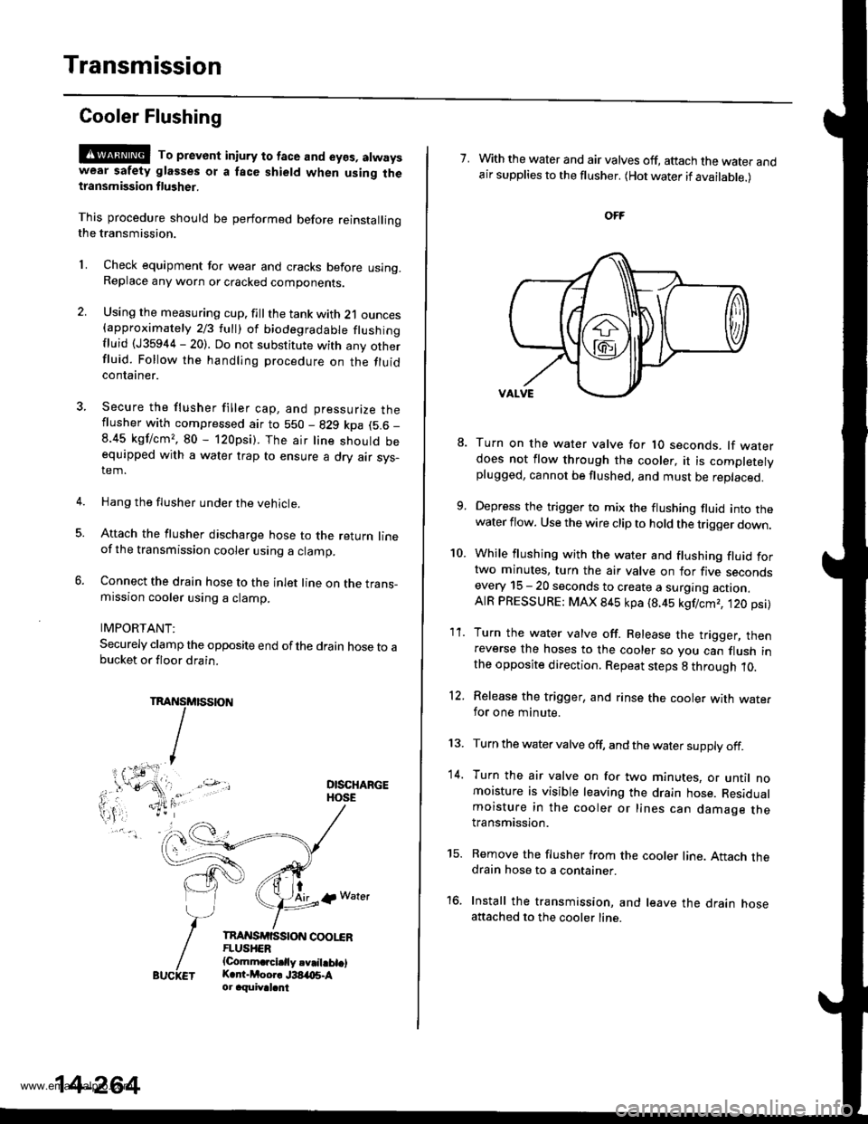
@@ To prevent in;ury to face and eyos, atwayswear safety glasses ot a face shield when using thetlansmission flusher.
This procedure should be performed before reinstallingthe transmission.
2.
LCheck equipment for wear and cracks before using.Replace any worn or cracked components.
Using the measuring cup. fill the tank with 21 ounces{approximately 213 lull) ol biodegradable flushingfluid (J35944 - 20). Do not substitute with any otherfluid. Follow the handling procedure on the fluidcontaaner.
Secure the flusher filler cap, and pressurize theflusher with compressed air to 550 - 829 kpa (5.6 _
8.45 kgf/cm,, 80 - 120psi). The air line should beequipped with a water trap to ensure a dry air sys-tem.
Hang the flusher under the vehicle.
Attach the flusher discharge hose to the return lineof the transmission cooler using a clamp.
Connect the drain hose to the inlet line on the trans-mission cooler using a clamp.
IMPORTANT:
Securely clamp the opposite end ofthe drain hose to abucket or floor drain.
DISCHARGEHOSE
tAirlp Water
TnAI{SrfiSStoN coot"€RFLUSHER{Comm.rcidly.v.il.bt.lK.r -Moor. J38,t{15.Aor aquival.nt
5.
14-264
7. With the water and air valves off, attach the water andair supplies to the flusher. (Hot water if available.)
10.
8.
1'�I.
Turn on the water valve for 1O seconds. lf waterdoes not flow through the cooler, it is completelyplugged, cannot be flushed, and must be replaced.
Depress the trigger to mix the flushing fluid into thewater flow. Use the wire clip to hold the trigger down.
While flushing with the water and flushing fluid fortwo minutes, turn the air valve on for five secondsevery 15 - 20 seconds to create a surging action.AIR PRESSURE: MAX 845 kpa (8.45 kgf/cmr, t20 psi)
Turn the water valve off. Release the trigger, thenreverse the hoses to the cooler so you can flush inthe opposite direction. Repeat steps 8 through 10.
Release the trigger, and rinse the cooler with wate.for one minute.
Turn the water valve off, and the water supply off.
Turn the air valve on for two minutes, or until nomoisture is visible leaving the drain hose. Residualmoisture in the cooler or lines can damage thetransmission.
Remove the flusher from the cooler line. Attach thedrain hose to a container.
Install the transmission, and leave the drain hoseattached to the cooler line.
12.
13.
14.
to.
www.emanualpro.com
Page 781 of 1395
17.Make sure the transmission is in E position.
Fill the transmission with ATF, and run the engine
for 30 seconds or until approximately 0.951 {1.0 US
qt., 0.8 lmp qt.) is discharged.
Remove the drain hose, and reconnect the cooler
return hose to the transmission (see page 14-266).
Refill the transmission with ATF to the proper level
(see page l4'161 ).
18.
19.
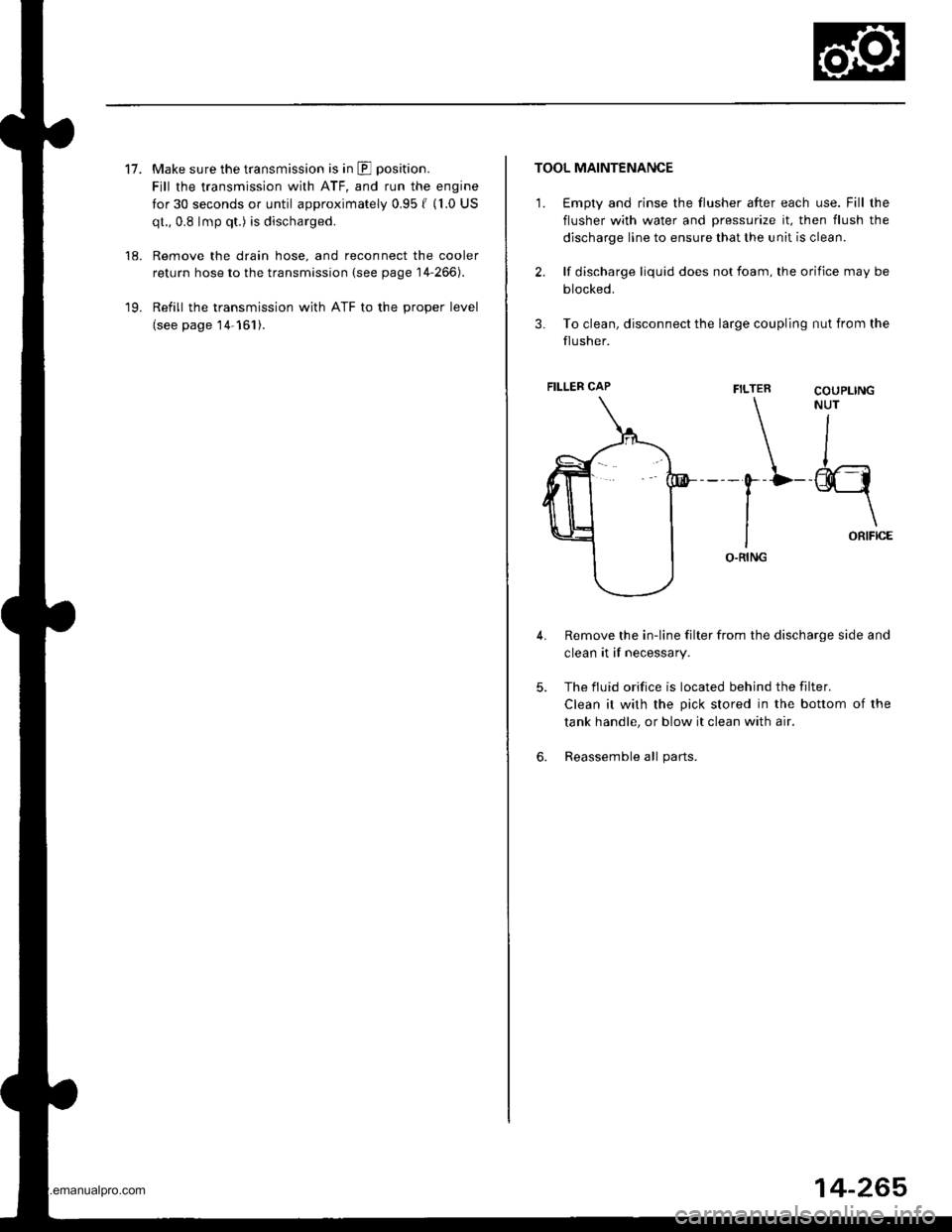
TOOL MAINTENANCE
1. €mpty and rinse the flusher after each use. Fill the
flusher with water and pressurize it, then flush the
discharge line to ensure that the unit is clean.
2. lf discharge liquid does not foam, the orifice may be
blocked.
3. To clean, disconnect the large coupling nut from the
flusher.
FILTER
\-0--D
I
IO.RING
Remove the in-line filter from the discharge side and
clean it if necessary.
The fluid orifice is located behind the filter.
Clean it with the pick stored in the bottom of the
tank handle, or blow it clean with air.
Reassemble all parts.
COUPLINGNUT
II
-@q
\ORIFICE
4.
5.
6.
FILLER CAP
14-265
www.emanualpro.com
Page 782 of 1395
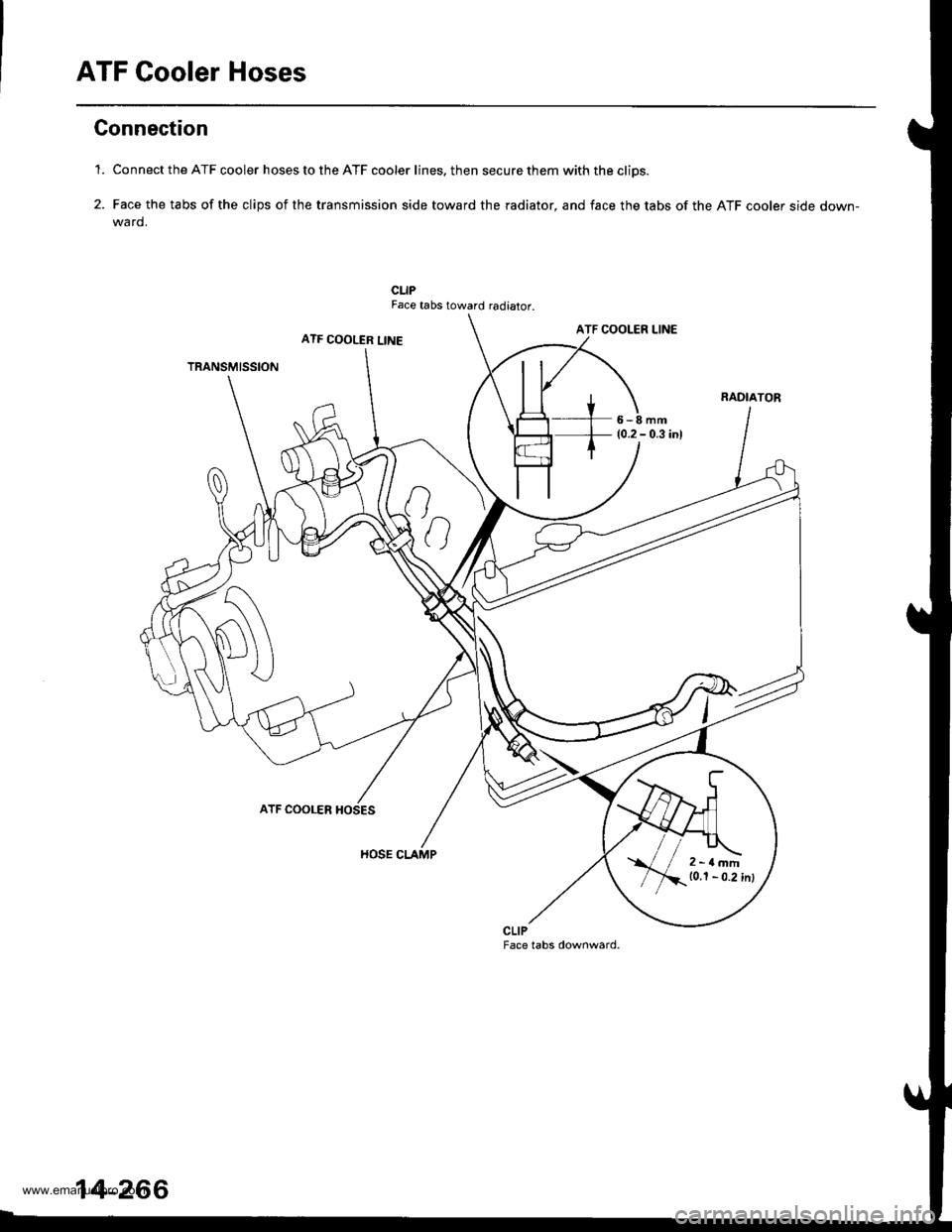
ATF Cooler Hoses
Gonnection
'1. Connect the ATF cooler hoses to the ATF cooler lines. then secure them with the cliDs.
2. Face the tabs of the clips of the transmission side toward the radiator, and face the tabs of the ATF cooler side down-wa rd.
CLIPFace tabs toward radiator.
ATF COOLER LINEATF COOLER LINE
TRANSMISSION
6-8mm(0.2 - 0.3 inl
ATF COOLER
HOSE CLAMP
CLIPFace tabs downward.
2-rlmm10.1 - 0.2 inl
14-266
www.emanualpro.com
Page 794 of 1395

Description
Rear Differential
Outline
The Real-time 4WD-Dual Pump System model has a hydraulic clutch and a differential mechanism in the rear differential
assembly. Under normal conditions, the vehicle is driven by the front wheels. However, depending on to the driving force
of the front wheels and the road conditions. the system instantly transmits appropriate driving force to the rear wheels
without requiring the driver to switch between 2WD (tront wheel drive) and 4WD (four wheel drive). The switching mecha-
nism between 2WD and 4WD is integrated into the rear differential assembly to make the system light and compact.
ln addition, the dual-pump system switches off the rear-wheel-drive force when braking in a forward gear. This allows the
braking system to work properly on models equipped with an Anti-lock Braking System (ABS).
Construction
The rear differential assembly consists of the torque control differential case assembly and the rear differential carrier
assembly. The torque control differential case assembly consists of the differential clutch assembly, the companion
flange, and the oil pump body assembly. The rear differential carrier assembly consists of the differential mechanism. The
differential drive and driven gears are hypoid gears.
The oil pump body assembly consists of the front oil pump, the rear oil pump, the hydraulic control mechanism, and the
clutch piston. The clutch piston has a disc spring that constantly provides the differential clutch assembly with a preset
torque to Drevent abnormal sound.
The clutch guide in the differential clutch assembly is connected to the propeller shaft via the companion flange, and it
receives the driving force lrom the transfer assembly. The clutch guide rotates the clutch plate and the front oil pump in
the oil pump body.
The clutch hub in the differential clutch assembly has a clutch disc that is splined with the hypoid drive pinion gear. The
hypoid drive gear drives the rear oil pump.
The front and rear oil pumps are trochoidal pumps. The rear oil pump capacity is 2.5 percent larger that the front oil pump
to handle the rotation difference between the front and rear wheels caused by worn front tires and tight corner braking.
The oil pumps are designed so the fluid intake works as a fluid discharge when the oil pumps rotate in reverse. Genuine
Honda CVT fluid is used instead of differential fluid.
Operation
When there is a difference in rotation speed between the front wheels (clutch guide) and rear wheels (hypoid driven gear),
hydraulic pressure from the front and rear oil pumps engages the differential clutch, and drive force from the transler
assembly is applied to the rear wheels.
The hydraulic pressure control mechanism in the oil pump body selects 4WD mode when the vehicle is started abruptly,
or when accelerating in a forward or reverse gear (causing rotation difference between the front and rear wheels). or
when braking in reverse gear {when decelerating). lt switches to 2WD mode when the vehicle is driven at a constant speed
in forwar! or reverse gear (when there is no rotation difference between the front and rear wheels), or when braking in a
fo rwa rd gear (when decelerating).
To protect the system, the differential clutch assembly is lubricated by hydraulic pressure generated by the oil pumps in
both 4WD and 2WD modes. Also, the thermal switch relieves the hydraulic pressure on the clutch piston and cancels 4WD
mode if the temDerature of the differential fluid rises above normal.
www.emanualpro.com