14-1 HONDA CR-V 1999 RD1-RD3 / 1.G User Guide
[x] Cancel search | Manufacturer: HONDA, Model Year: 1999, Model line: CR-V, Model: HONDA CR-V 1999 RD1-RD3 / 1.GPages: 1395, PDF Size: 35.62 MB
Page 534 of 1395
Description
Electronic Control System (cont'dl
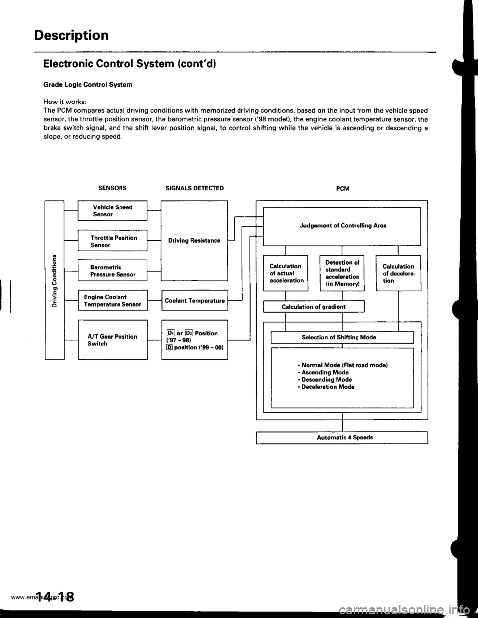
Grade Logic Control System
How it works:
The PCM compares actual driving conditions with memorized driving conditions, based on the input from the vehicle speed
sensor, the throttle position sensor, the barometric pressure sensor ('98 model). the engine coolant temperature sensor, the
brake switch signal, and the shift lever position signal, to control shifting while the vehicle is ascending or descending a
slope, or reducing speed.
SIGNALS DETECTED
Driving Rcsisl.nce
Judgemont ot Controlling Aroa
. Normal Modo {Flrt ro.d mode}. Ascending Mode. Deacending Mode. Deceleration Mode
14-14
www.emanualpro.com
Page 535 of 1395
![HONDA CR-V 1999 RD1-RD3 / 1.G User Guide
Ascending Control {37 Modol}
When the PCM determines that the vehicle is climbing a hill in E] and E positions, the system extends the engagement
area of 2nd g€ar and 3rd gear to prevent the transm HONDA CR-V 1999 RD1-RD3 / 1.G User Guide
Ascending Control {37 Modol}
When the PCM determines that the vehicle is climbing a hill in E] and E positions, the system extends the engagement
area of 2nd g€ar and 3rd gear to prevent the transm](/img/13/5778/w960_5778-534.png)
Ascending Control {37 Modol}
When the PCM determines that the vehicle is climbing a hill in E] and E positions, the system extends the engagement
area of 2nd g€ar and 3rd gear to prevent the transmission from frequently shifting between 2nd and 3rd gears, and
between 3rd and 4th gears, so the vehicle can run smooth and have more power when needed.
NOTE:
. Shift schedules stored in ths PCM between 2nd and 3rd gears, and between 3rd and 4th gears. enable the PCM's fuzzy
logic to automatically select the most suitable gear according to the magnitude of 8 gradient.
t Fuzzy logic is a form of artificial intslligence that lets computers respond to changing conditions much like a human
mind would.
3RD - tlTHASCENoING MODE: UFhift Sch.dulc
- . FLAT ROAD MODE
-----------. : GRADUAL ASCENDING MODE
- - - - - : STEEPASCENDING MODEo5l)
FFN1NS
7,.,.7a
: 2ND-3RD SHIFTING CHARACTERISTICSCONTROL AREA| 3RD-aTH SHIFTING CHARACTER|SnCSCONTROL AREA
62 mph
1100 km/h)Vehicle .o..d
Asconding Conirol ('98 - 00 Mod.ls)
When the PCM determines that the vohicle is climbing a hill in E] and E positions ('98 model), and in E] position ('99 -
00 models), the system extends the engagement srea of 2nd gear and 3rd gear to prevent the transmission from frequent-
ly shifting between 2nd and 3rd gears, and between 3rd and 4th gears, so the vehicle can run smooth and have more
power when needed.
NOTE: Shift schedulss stored in the PCM between 2nd and 3rd gears, and between 3rd and 4th gears, enable to selsct the
most suitable gear according to th6 magnitude of a gradi€nt.
ASCENDING MODE: Up.hift Sch.dul.
NN : 2ND-3RD SXImNG CHARACTERISTICS- GoNTRoLAREA
VVVVVZ:IRD-ITHSHIFnNGCHARACTERISTICS- cot{TRoL AREA
850
o
6:l mph11fl) km/hl
(cont'd)
2ND - 3RD
2ND + 3RD 3RD + 4TH
Vahicl. sDctd
14-19
www.emanualpro.com
Page 578 of 1395
Symptom-to-Component Chart
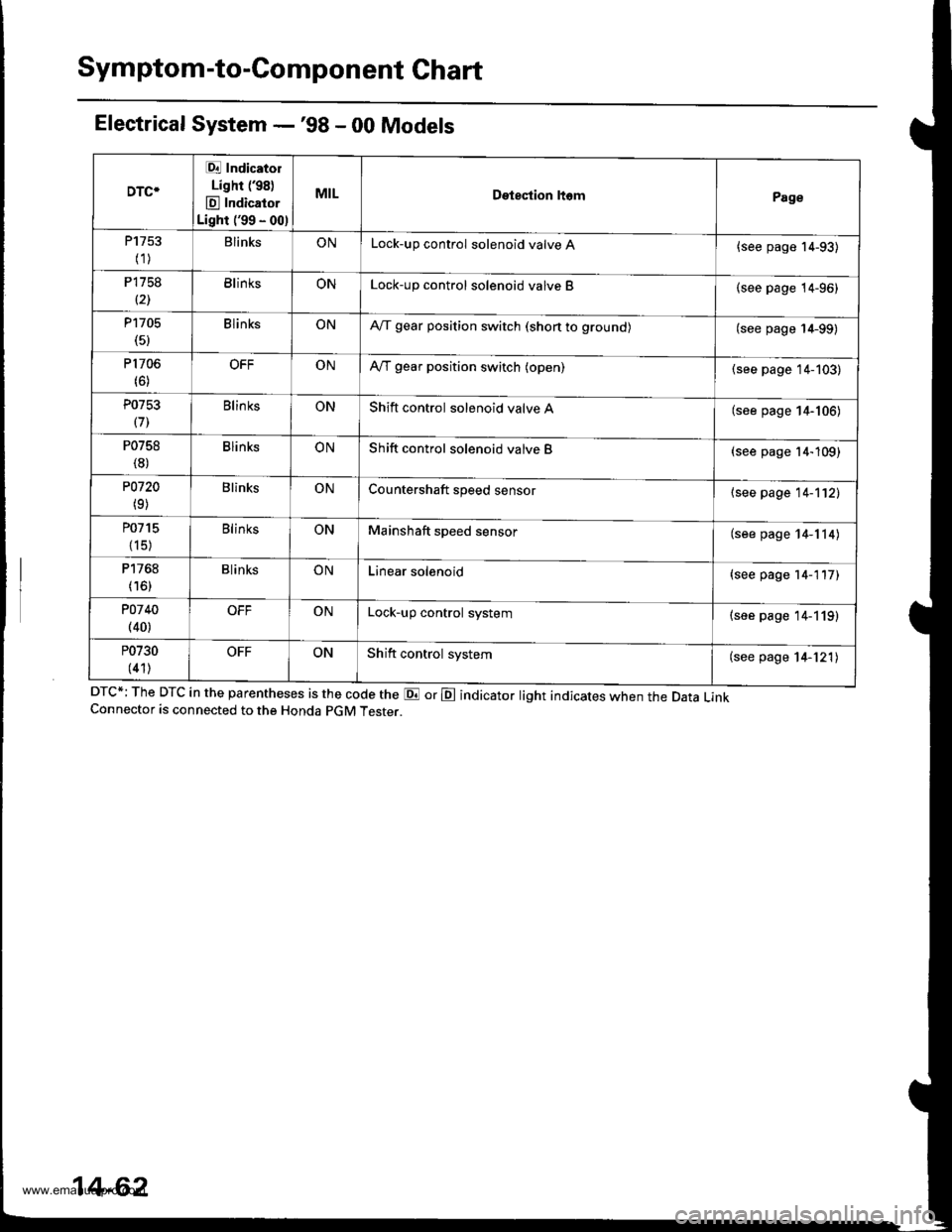
Electrical System -'98 - 00 Models
DTC*; The DTC in the parentheses is the code the E or E indicator light indicates when the Data LinkConnector is connected to the Honda pGM Tester.
DTC*
Et Indicatol
Lighr (98)
E Indicator
Light ('99 - 00)
MILDetestion ltomPage
P1753
(1)BlinksONLock-up control solenoid valve A{see page 14-93)
P1758
(21BlinksONLock-up control solenoid valve B(see page 14-96)
P1705(5)BlinksONA,/T gear position switch (shon to grounol(see page 14-99)
P1706(6)OFFONA,/T gear position switch (open)(see page 14-103)
P0753
(71Blin ksONShift control solenoid valve A(see page 14-106)
P0758
(8)BlinksONShift control solenoid valve B(see page 14-109)
P0720
(9)BlinksONCountershaft speed sensor{see page 14-112)
P0715
{15)
BlinksONMainshaft speed sensor(see page 14-114)
P1768
(16)BlinksONLinear solenoid(see page 14-117)
POl 40(40)OFFONLock-up control system(see page 14-119)
P0730
(41)OFFONShift control system(see page 14-121)
14-62
www.emanualpro.com
Page 579 of 1395
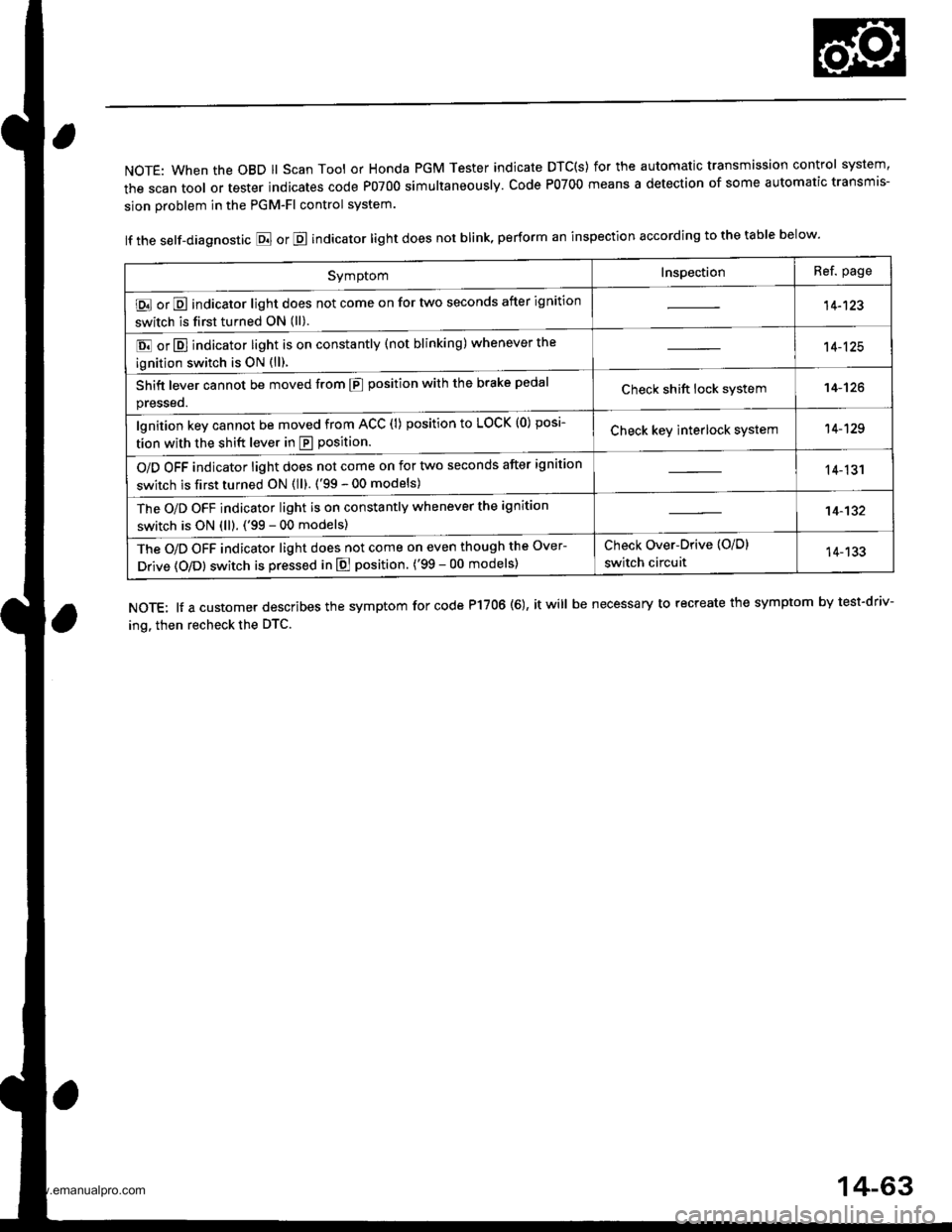
NOTE: When the OBD ll Scan Tool or Honda PGM Tester indicate DTC(S) for the automatic transmission control system,
the scan tool or tester indicates code P0700 simultaneously. Code P0700 means a detection of some automatic transmis-
sion problem in the PGM-Fl control system.
lf the self-diagnostic E or E indicator light does not blink, perform an inspection according to the table below.
NOTE: lf a customer describes the symptom for code P17OO (6), it will be necessary to recreate the symptom by test-driv-
ing. then recheck the DTC.
SymptomInspectionRef. page
E or E indicator light does not come on for two seconds after ignition
switch is first turned ON (ll).14-123
E or E] indicator light is on constantly (not blinking) whenever the
ignition switch is oN {ll).
14-125
Shift lever cannot be moved from E position with the brake pedal
presseo.Check shift lock system14-'t26
lgnition key cannot be moved from ACC (l) position to LOCK (0) posi-
tion with the shift lever in E position.Check key interlock system14-129
O/D OFF indicator light does not come on for two seconds after ignition
switch is first turned ON (ll). ('99 - 00 models)14-131
The O/D OFF indicator light is on constantly whenever the ignition
switch is ON (ll). ('99 - 00 models)14-132
The O/D OFF indicator light does not come on even though the Over-
Drive (O/Dl switch is pressed in E position. ('99 - 00 models)
Check Over-Drive {O/D}
switch circuit14-133
14-63
www.emanualpro.com
Page 598 of 1395
Electrical Troubleshooting ('97 Model)
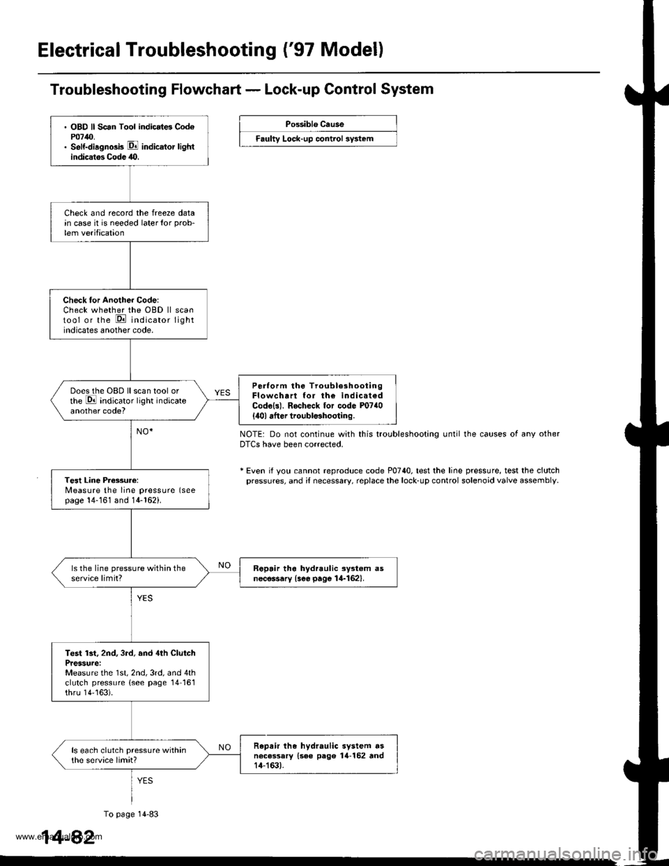
. OBD ll Scan Tool indicrt6 Cod6P0740.. Self-diagno3b E indicator lightindicatos Codc 40.
Check and record the freeze datain case it is needed laterlor prob-
lem verification
Check tor Another Code:Check whether the OBD ll scantool or the E indicator lightindicates another code.
Perlorm the TroubleshootingFlowchart lor th€ indicat€dCodo{s). Rocheck tor code P0740
{ilol after troubl$hooting.
Does the OBD ll scan tool orthe E indicator light indicateanother code?
Tesl Line Pressure:Measure the line pressure (seepage 14-161 and 14-162).
ls the line pressure within theservice limit?R6pair tho hydraulic ayst€m asnecessary {see page 14-162}.
Test lst, 2nd, 3rd, and 4th ClutchPressure:Measure the 1st, 2nd, 3rd, and 4thclutch pressure (see page 14161thru 14''163).
Repair the hydraulic system dsnecessary {see pago 14-152 rnd14-163).
ls each clutch pressure withinthe service limit?
Troubleshooting Flowchart - Lock-up Control System
Possiblo Cause
Faulty Lock-up control sy3t6m
NOTE: Do not continue with this troubleshooting until the causes of any otherDTCS have been corrected.
* Even if yotl cannot reproduce code P0740. test the line pressure, test the clutchpressures, and i{ necessary, replace the lock-up control solenoid valve assembly
1
To page 14-83
4-82
www.emanualpro.com
Page 599 of 1395
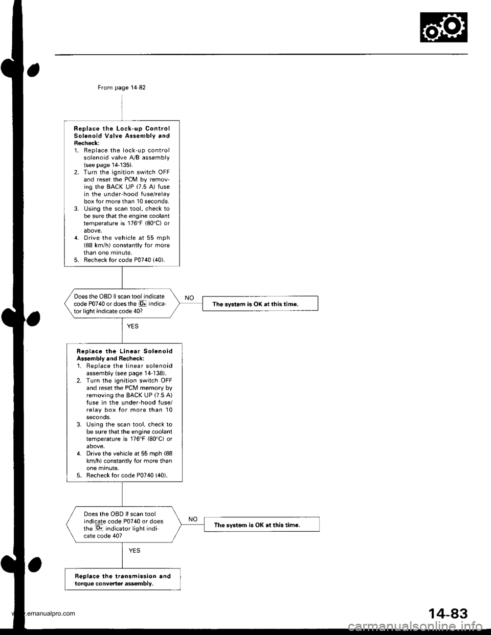
From page 14 82
Replace the Lock-up ControlSolenoid Valve Assembly andRecheck:1. Replace the lock-up controlsolenoid valve A/B assembly(see page 14-'135).2. Turn the ignition switch OFFand reset the PCM by remov-ing the BACK uP (7.5 A) fusein the under-hood fuse/relaybox for more than 10 seconds.3. lJsing the scan tool, check tobe sure that the engine coolanttemperature is 176"F 180'C) orabove,4. Drive the vehicle at 55 mph(88 km/h) constantly for moretnan one mrnute.5. Recheck for code P0740 (40).
Does the OBD ll scan tool indicatecode PO74O or doesthe El indicator light indicate code 40?The svstem is OK ai this time.
Replace the Linear Sol€noidA$embly and Recheck:'1. Beplace the linear solenoidassembly {see page 14-138).2. Turn the ignition switch OFFand reset the PCM memory byremoving the BACK UP (7.5 A)fuse in the underhood fuse/relay box for more than 10seconds.3. Using the scan tool, check tobe sure that the engine coolanttemperature is 176"F (80'C) orabove.4. Drive the vehicle at 55 mph (88
km/h) constantly for more thanone minute,5. Recheck for code P0740 {40).
Does the OBD ll scan toolindicate code P0740 or doesthe E indicator light indicate code 40?
The svsteo is OK at this tim€.
Replace the transmission andtorque convertor assembly.
www.emanualpro.com
Page 600 of 1395
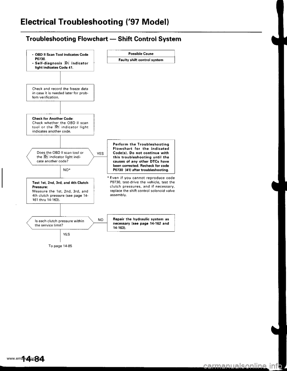
Electrical Troubleshooting ('97 Model)
Troubleshooting Flowchart - Shift Control System
Possible Cause
F""lty "t lft ".tttr"l "y"t..
+ Even it you cannot reproduce codeP0730, test drive the vehicle, test theclutch pressures, and if necessary,replace the shift control solenoid valve
. OBD ll Scan Tool indicates CodeP0730.. Selt-diagnosis E,l indicatorlight indicates Code 41.
Check and record the freeze datain case it is needed later for prob-lem verification.
Check tor Another Code:Check whether the OBD ll scantool or the Pll indicator lightindicates another code,
Pertorm the TroubleshootingFlowchart for the indicatedCodels). Do not conlinu€ withthis troubleshooting until thecauses of anv other DTCS havebeen corrected. Recheck for codeP0730 {41) after troubloshooting.
Does the OBD ll scan tool orthe E indicator light indi-cate another code?
Test lst. 2nd, 3rd. and 4th ClutchPressure:Measure the 1st, 2nd, 3rd, and4th clutch pressure (see page 14-161 thru 14-163).
Repair the hydraulic svstem asnecessary lsee page 1,1-162 andr4-1631.
ls each clutch pressure withinthe service limit?
To page 14-85
www.emanualpro.com
Page 601 of 1395
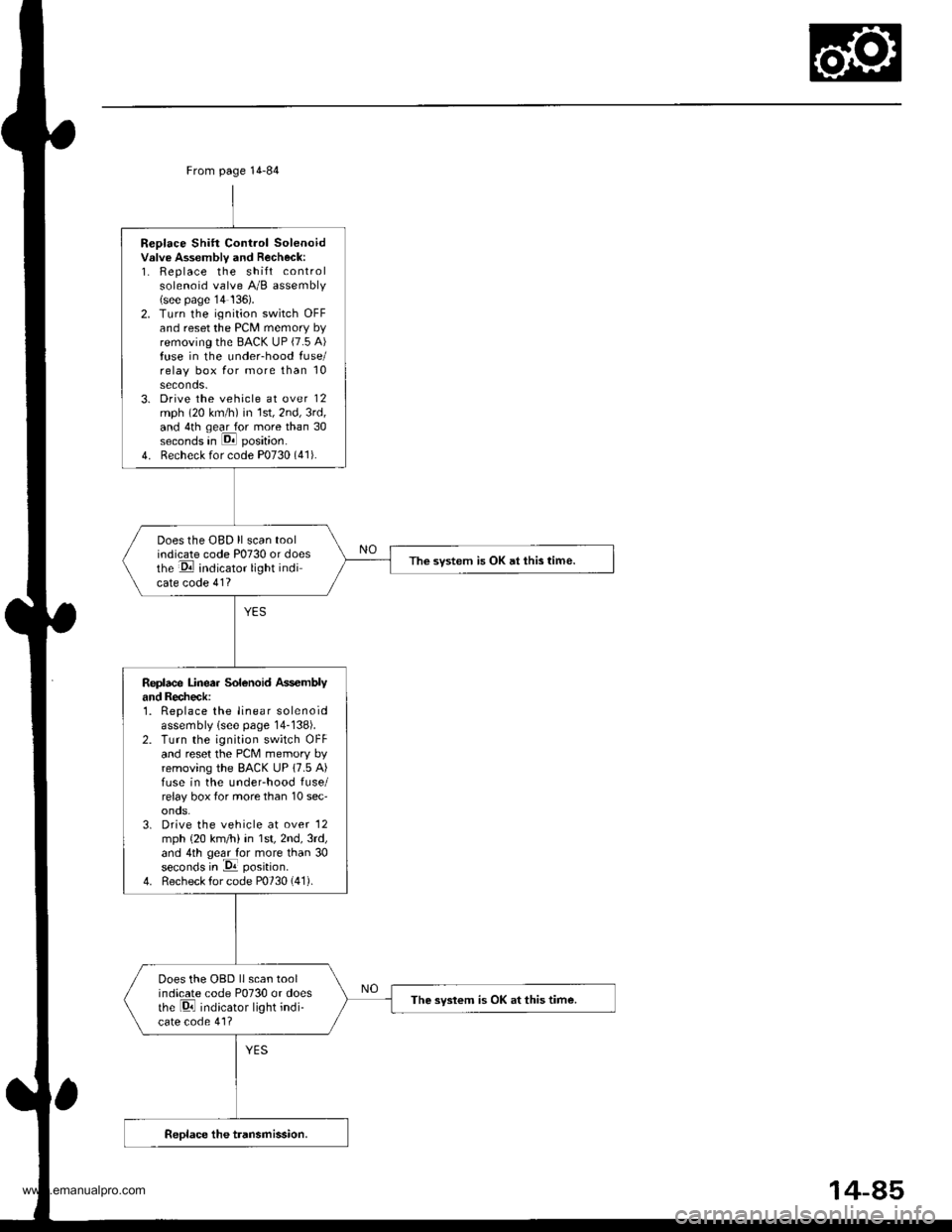
Replace Shift Control Solenoidvslve Assembly and Recheck:1. Replace the shift controlsolenoid valve A/B assembly(see page'14 136).2. Turn the ignition switch OFFand reset the PCM memory byremoving the BACK UP (7.5 A)fuse in the under-hood fuse/relay box for more than 10seconds.3. Drive the vehicle at over 12mph (20 km/h) in 1st,2nd,3rd,and 4th qear for more than 30seconds in E position.
4. Recheck for code P0730 (41).
Does the OBD ll scan toolindicate code P0730 or doesthe E indicator light indicate code 41?
The svstem is OK at this time.
Replace Linea. Solenoid Ass€mblyand Recheck:1. Replace the linear solenoidassembly lsee page 14-138).2. Turn the ignition switch OFFand reset the PcM memory byremoving the BACK UP 17.5 A)fuse in the underhood fuse/relay box tor more than 10 sec'onos.3. Drive the vehicle at over '12
mph {20 km/h) in 1st,2nd,3rd,and 4th geal for more than 30seconds in -Da position.
4. Recheck for code P0730 (41).
Does the OBD llscan toolindicate code P0730 or doesthe Di indicator light indi-cate code 41?
The syslem is OK at this time.
From page 14-84
14-85
www.emanualpro.com
Page 615 of 1395
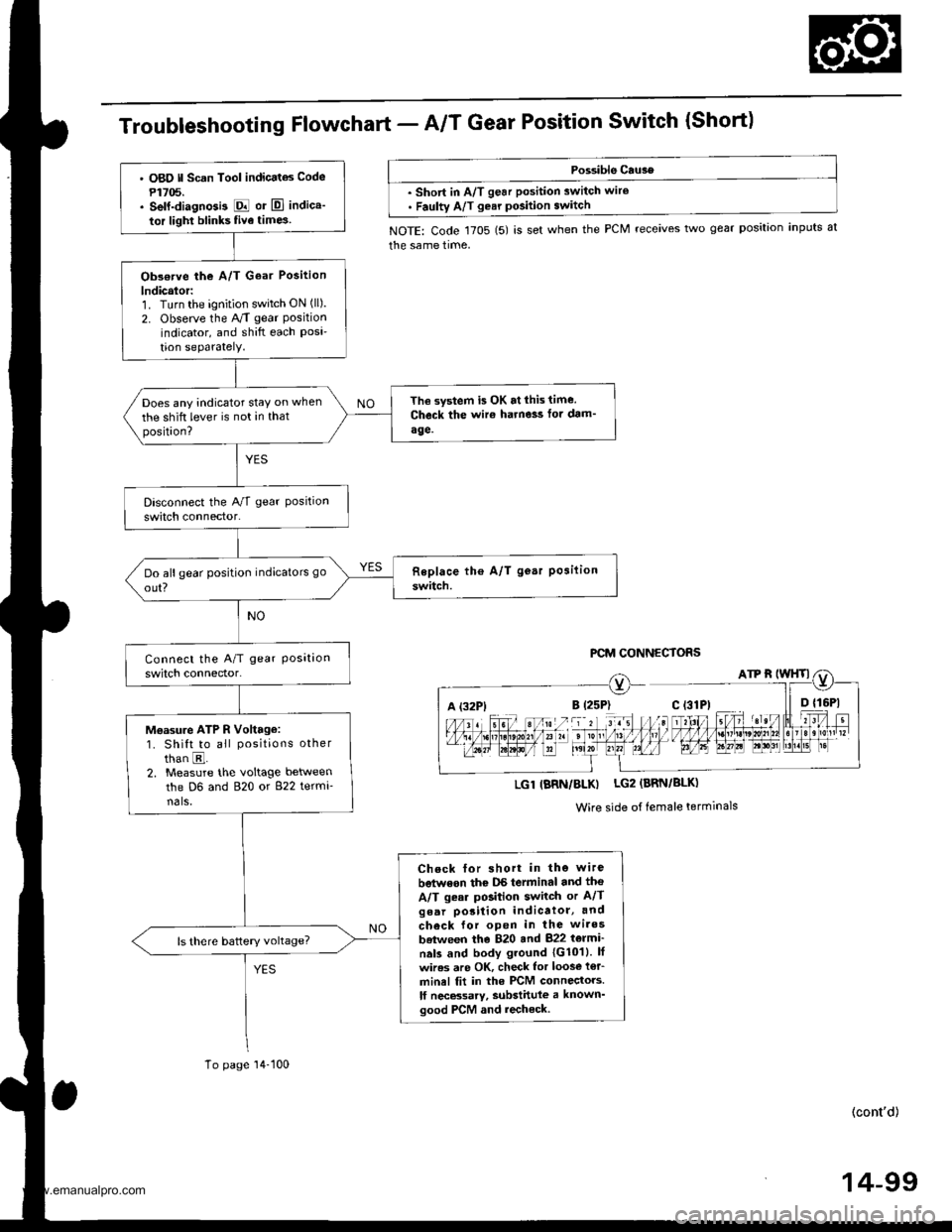
TroubleshootingFfowchart - AIT Gear Position Switch {Short)
Possible Cau3e
. short in A/T gear position switch wire. Faulty A/T gear pGition switch
NOTE: Code 1705 (5) is set when the PCM receives two gear position inputs at
the same time,
PCM CONNECTORS
A (32P1
LGl IBRN/BLK) LG2 (BRN/BLK)
Wire side of female terminals
' O8O ll Scan Tool indicatas Code
P1705.. self-diagnGi3 E or El indica'
tor light blinks five time3
Obs€rve the A/T Goar Position
lndicalor:1. Turn the ignition switch ON (ll).
2. Observe the A/T gear Positionindicator, and shift each Posi'tion seParatelY.
The system is OK at lhis time.
Check the wir€ harne3s fot dam'
age.
Does any indicator stay on when
the shift lever is not in thatposition?
Moasu.e ATP R Voltage:1. Shift to all positions other
than E.2. Measure the voltage between
the D6 and 820 or 822 termi-nals,
Check for short in the wire
betwoon thc DS terminal and tho
A/T gear position switch or A/Tgear porition indicatol, and
check for open in the wires
batween the 820 and 822 t6lmi'
nals and body ground 1G1011. lf
wires are OK, check lor loos€ i€r_
minel fit in the PCM connectors.
lf necBsarv, substittlle a known'good PCM and recheck.
To page'14-100
(cont'd)
14-99
www.emanualpro.com
Page 616 of 1395
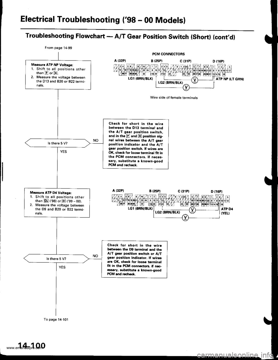
Electrical Troubleshooting ('98 - 00 Modelsl
Troubleshooting Flowchart - A/T Gear position switch (short) (cont'dl
FCM CONNECTORS
B t25Plc (31P)
Wire side of lemale terminals
A t32Pl
LGl {BRN/BLK)
From page 1 4-99
To page 14-101
Measur. ATP NP Voltago:1. Shift to all positions otherthan E or E.2. Measure the voltage belweenthe 013 and 820 or 822 termi-nats.
Check for short in the wir6b.twoen tha Dl3 terminal andthe A/T go.r polition 3witch,and in th6 El and E poiition sig-nal wir.! betwoen the A/T garrpo3ition indicetor and the A/Tgarr position switch. lf wi.6s areOK, check for loole torminal fit intho PCM connccto.s, lf necca-sary, lubstituto a known-goodPCM and rocheck.
Mcrsure ATP D4 Vohrg6:1. Shift to all positions otherthan E {'98) or El ('99 - oo).2. Measure the voltage betweenthe Dg and 820 or 822 termi-nals.
Check tor Bhort in the wi..bctw6cn thg Dg torminal and theA/T ge.r position .witch or A/Tgeor poaition indicator. lf wiaaaare OK, ch.ck lor loose torminalfit in the PICM conn.cto6. lf n€c-e3sary, subgthute r lnown-goodrcM and roch6d(.
ATP NP ILT GRNI
a t32Pl
LGl IERN/BLK}
14-100
www.emanualpro.com