HONDA CR-V 1999 RD1-RD3 / 1.G User Guide
CR-V 1999 RD1-RD3 / 1.G
HONDA
HONDA
https://www.carmanualsonline.info/img/13/5778/w960_5778-0.png
HONDA CR-V 1999 RD1-RD3 / 1.G User Guide
Page 1243 of 1395
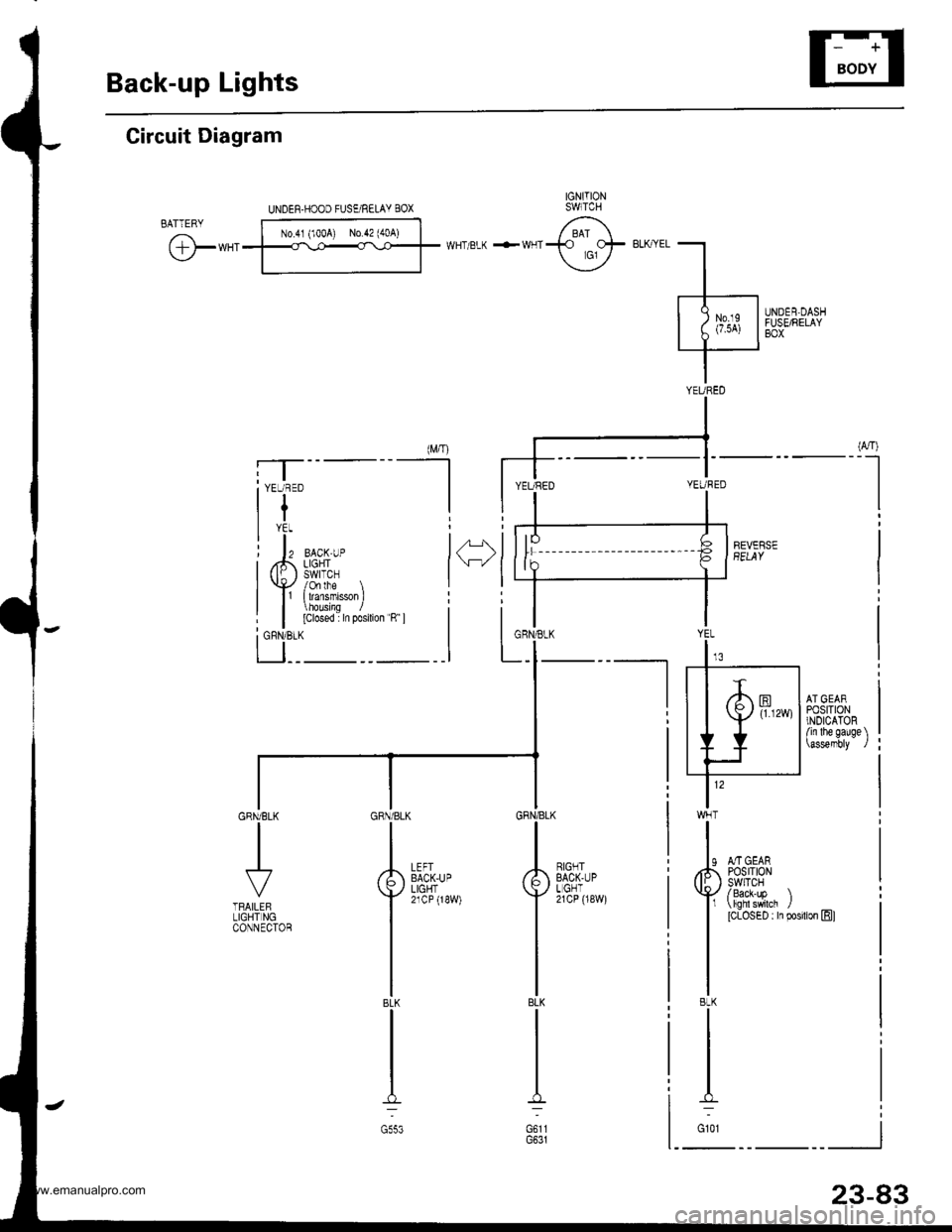
Back-up Lights
Circuit Diagram
(M/r)
I
I
8LK
I
G101
GRN/BLK
I
TBLK
I
UNDEN-HOOD FUSE/RELAY BOX
BACK,UPLIGHTswtTcH/0n1he \I lransmisson J
o!s { /lolosed : In posilion R l
LEFIBACK,UPLIGHT21CP (18W)
*"_,,. _*,,@_ "*"
]__
_..'
iu.Er.w
-r-
RIGHTBACK,UPLGHT21CP 08W)
A,/IGEARPosrl0NswtTcH/Back'up \\l€hl swilch ,/ICLOSED : In posilion [8ll
www.emanualpro.com
Page 1244 of 1395
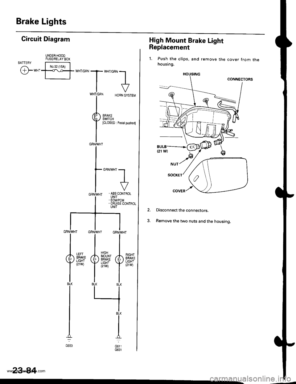
Brake Lights
High Mount Brake Light
Replacement
1. Push the clips, and remove the cover from thehousing.
Disconnect the connectors.
Remove the two nuts and the housing.
2.
HOUSING
Gircuit Diagram
UNDER.HOODFUSE/RELAY BOXBATTENY
/,i | No.s2 {15A) |
\Y*-I=f*-'o*T*'no"l
IV
T:,^-,
HORNSYSTEM
I
i.t53l| *",*"",
GRNA,VHT
GBNMHT -.1
I
I
. ABS CONTFOLUNIT' ECM/PCM. CRUISE CONTROLUNIT
GRNAVHT GRNWH
ll
tl
A[$^Jlr A
Yi,?'il Y
tlBLK BLK
llrl
IBLK
I
I
d
oi,,
RIGHTEFAKELIGHT(21w)
LEFIBFAKELIGHT(2rw)
BLK
G553
23-84
www.emanualpro.com
Page 1245 of 1395
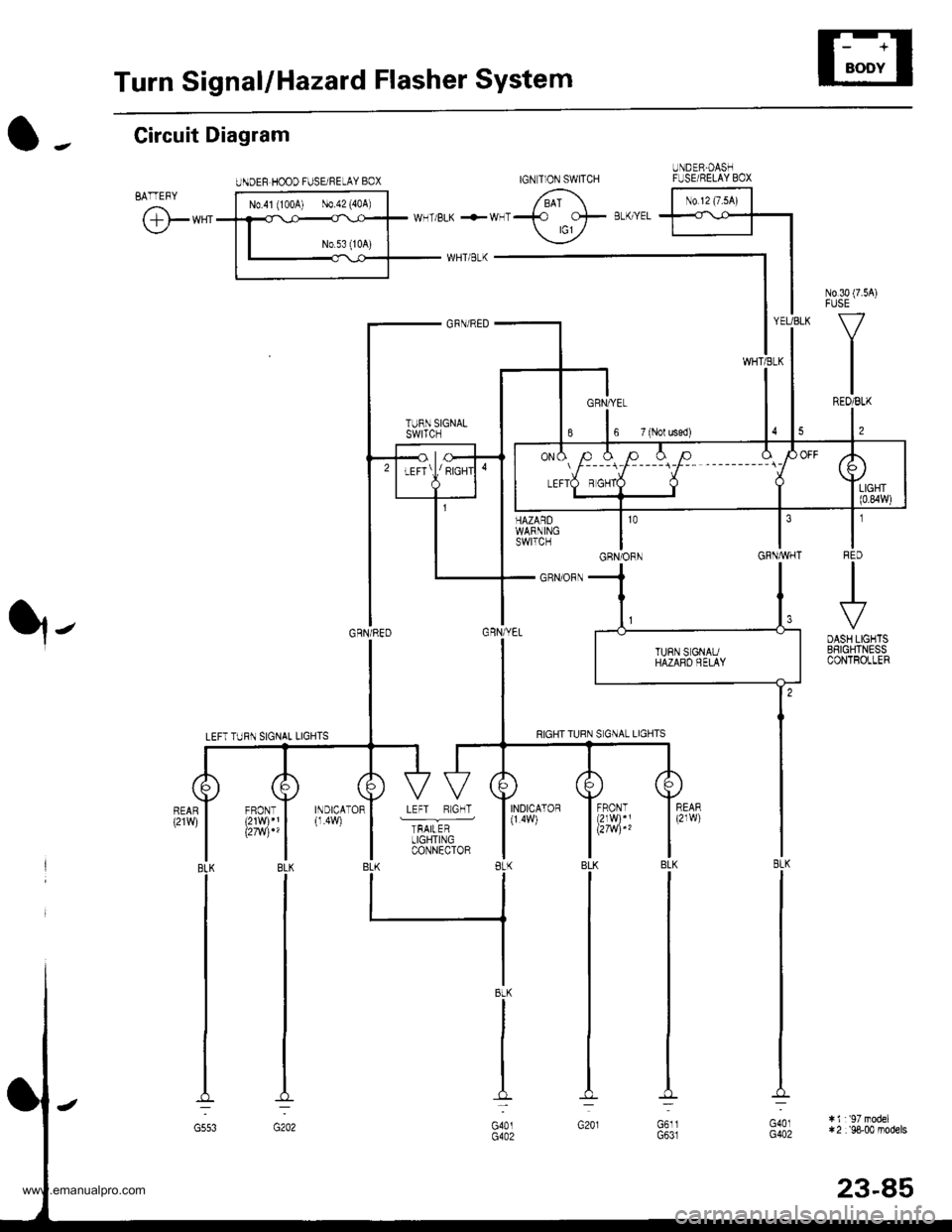
Turn SignallHazard Flasher System
UNDEF HOOD FUSE/NELAY BOX
N0.30 (7.54)FUSE
V
IREO/BLK
l,
t'IFqD
.+
DASH LIGHTSBSIGHTNESSCONTROLLER
HAZARDWARNINGswtTcH
_ GRN/ORN
YEUBLK
WHTiELK
GRNAVHT
O -. Circuit Diagram
BATTEFY
@**'
q-
103
GRN/ORN
INDICATOR
TFAILERLIGHTINGCONNECTOR
INDICATOR(1.4W)
BLK
G553
IGN T]ON SWITCHUNDER.OASHFUSE/RELAY BOX
No 12 (7.sA)
l----r-l-----i-F-- --------_ \
BtK
G401G402
:i1r'97model*2 :'98-00 models
23-85
www.emanualpro.com
Page 1248 of 1395
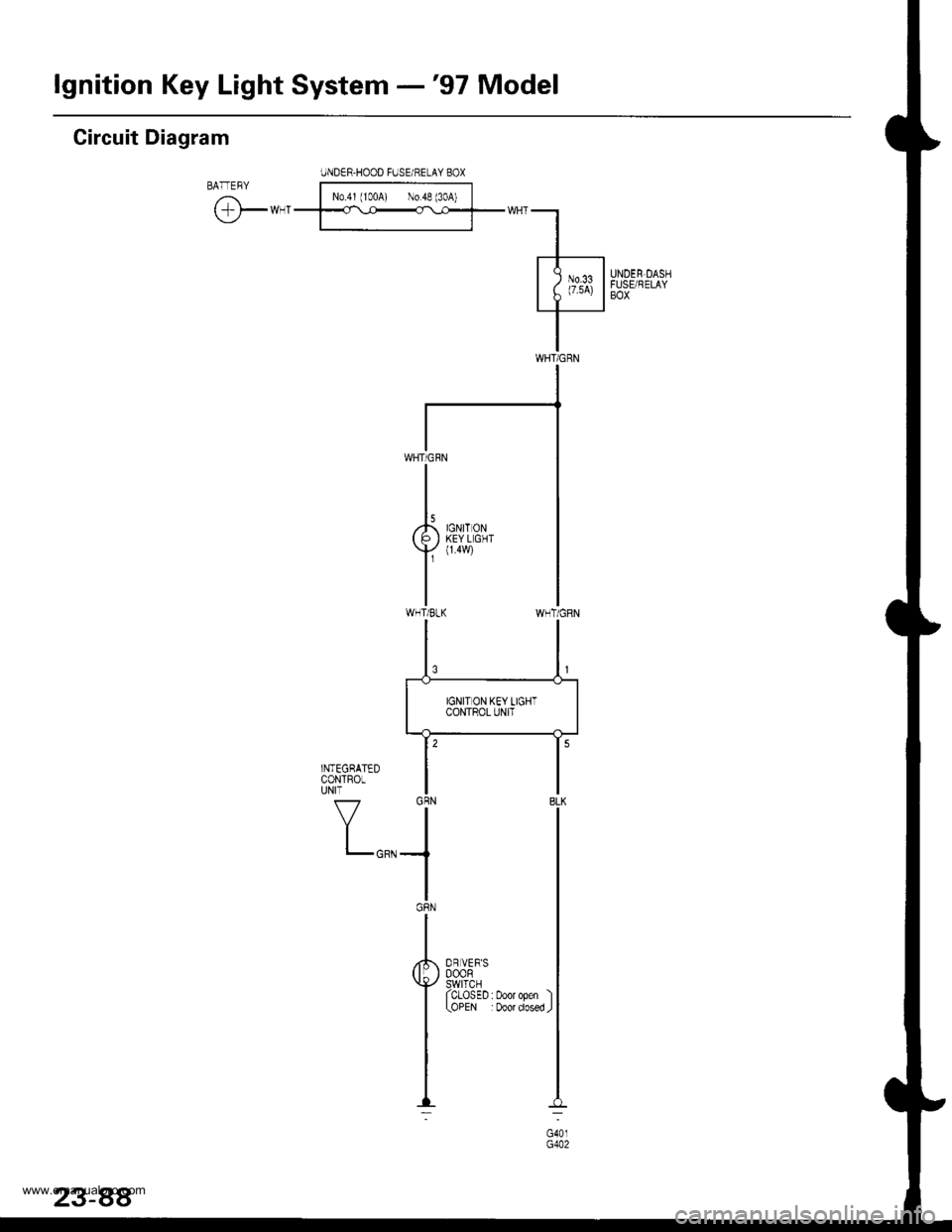
lgnition Key Light System -'97 Model
Circuit Diagram
IJNDER-HOOD FUSE/HELAY BOXBATEBY l-Noj',roo{ l;;f
tF*-'--ff::f-*"-l
.l-----
| ; )"t li|illsx"r
I
WNT/GRN
WHT/CRN
I
,k ,0r,, o,u( P I KEYLGHT
Y
{14w)
IWHT/BLK
OR VER'S000R9!rl9rl^ ^I ULU5EU:UOOrOpen I(OPEN :Door dosed J
www.emanualpro.com
Page 1250 of 1395
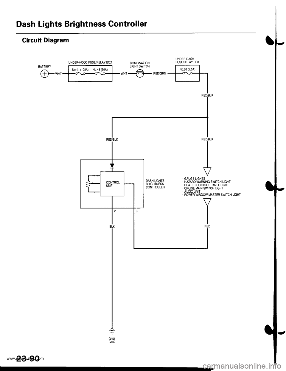
Dash Lights Brightness Controller
Circuit Diagram
23-90
G401
www.emanualpro.com
Page 1310 of 1395
)
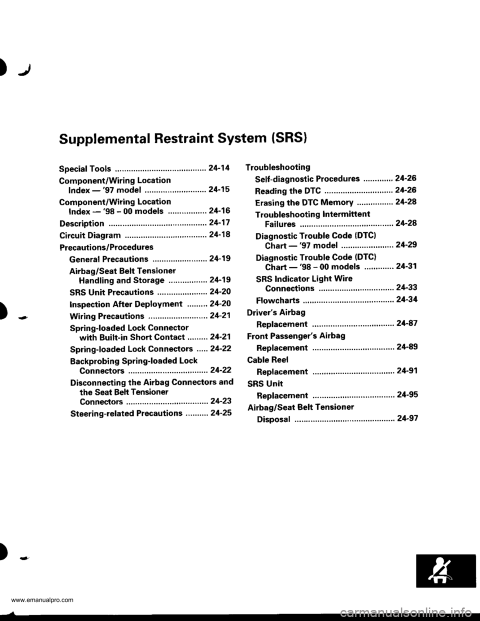
Supplemental Restraint System (SRS)
Special Tools .."....."" 24-14
Component/Wring Location
lndex - '97 model ..........'.." '.....""" 24-15
Component/Wiring Location
lndex - '98 - 00 models ..............." 24-16
Description .'.........."'.24'17
Circuit Diagram .........24'14
Precautions/Procedures
General Precautions ......".."'........... 24-19
Airbag/Seat Belt Tensioner
Handling and Stolage ....''........... 24-19
SRS Unit Precautions ...............'...... 24-20
lnspeciion After Deployment .......'.24'20
)
SpringJoaded Lock Connector
with Built-in Short Contact '...'....24-21
Spring-loaded Lock Connectors .."' 24-22
BackProbing SPring-loaded Lock
Conneetors ,.......24-22
Disconnecting the Airbag Connectors and
the Seat Beh Tensioner
Connectors ....'....24-23
Steering-lelated Precautions .......... 24-25
Troubleshooting
Self -diagnostic Procedures ............. 24-26
Reading the DTC .................. .....".."' 24'26
Erasing the DTC Memory ................24-28
Troubleshooting lntermittent
Faifures "'...........24'24
Diagnostic Trouble Gode {DTC}
Chart -'97 model ....""....... "......24-29
Diagnostic Trouble Gode (DTCI
Chart -'98 - 00 models ............. 24-31
SRS Indicator Light Wire
Connections ','," 24'33
Ff owcharts ....-........24'34
Driver's Airbag
Repf acement ..'......21'87
Front Passenger's Airbag
Repfacement .....'.',24'AS
Gable Reel
Replacement .......'.24-91
SRS Unit
Replacement .........24-95
Airbag/Seat Belt Tensioner
Disposaf .................24'97
)-e
www.emanualpro.com
