Rear seat removal HONDA CR-V 1999 RD1-RD3 / 1.G User Guide
[x] Cancel search | Manufacturer: HONDA, Model Year: 1999, Model line: CR-V, Model: HONDA CR-V 1999 RD1-RD3 / 1.GPages: 1395, PDF Size: 35.62 MB
Page 1049 of 1395
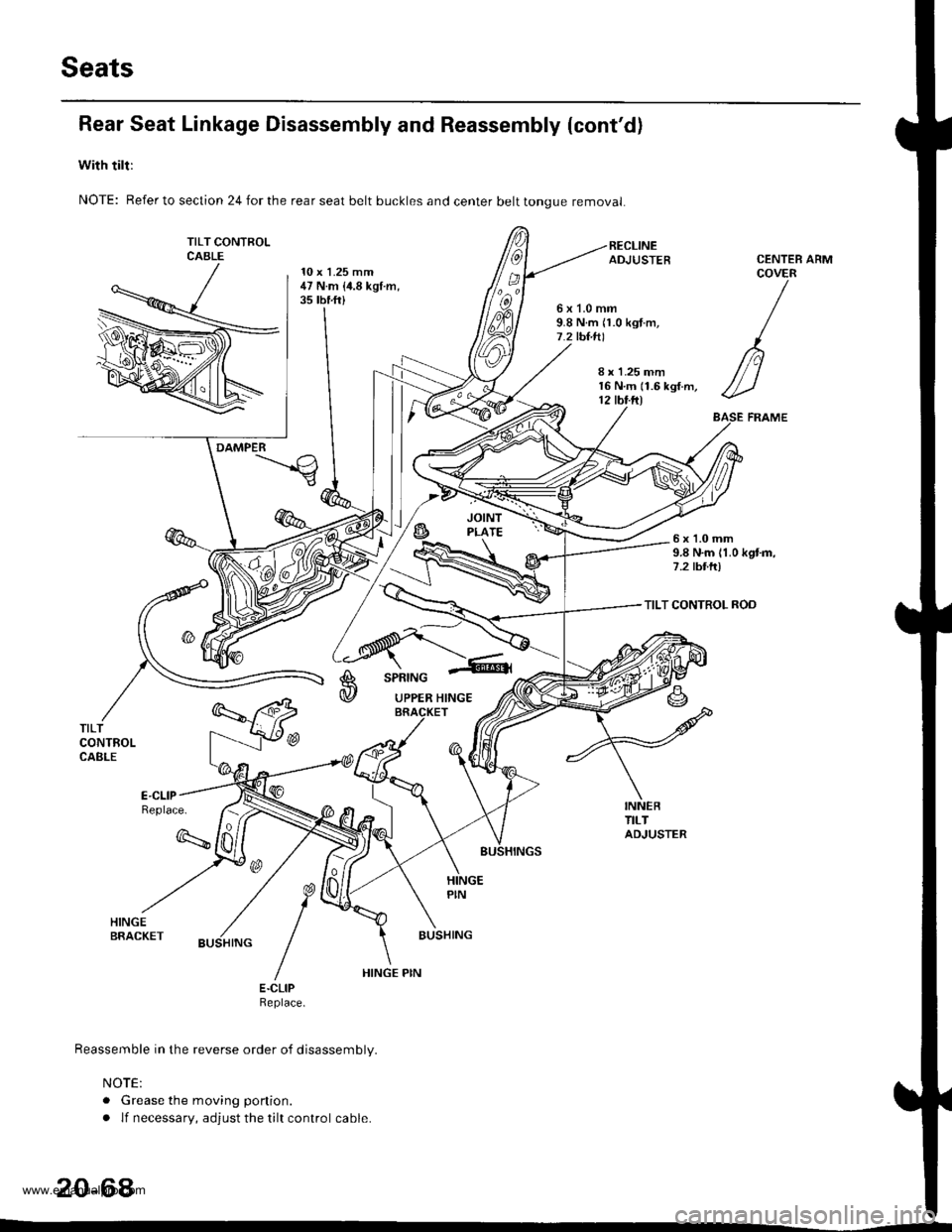
Seats
Rear Seat Linkage Disassembly and Reassembly (cont'd)
with tilt:
NOTE: Refer to section 24 for the rear seat belt buckles and center belt tongue removal
TILT CONTFOLCABLE10 x 1.25 mm47 N.m {i1.8 kgt.m,35 tbf.ft)
ARM
6x1.0mm9.8 N.m n.0 kgt.m,7.2 tbt.tll
CENTEBCOVER
/
n
//-)
ASE FRAME
8 r 1.25 mm16 N.m (1.6 kgf.m,12 tbt.ftl
DAMPER
6x1.0mm9.8 N.m 11.0 kgtm,7.2 tbttr)
TILT CONTROL ROD
A
@
SPRING
UPPER HINGE
TILTCONTROLCABLE
Replace.
q
BUSHING
E.CLIPReptace.
Reassemble in the reverse order of disassembly.
NOTE:
. Grease the moving ponion.
. lf necessary, adjust the tilt control cable.
20-64
HINGE PIN
www.emanualpro.com
Page 1050 of 1395
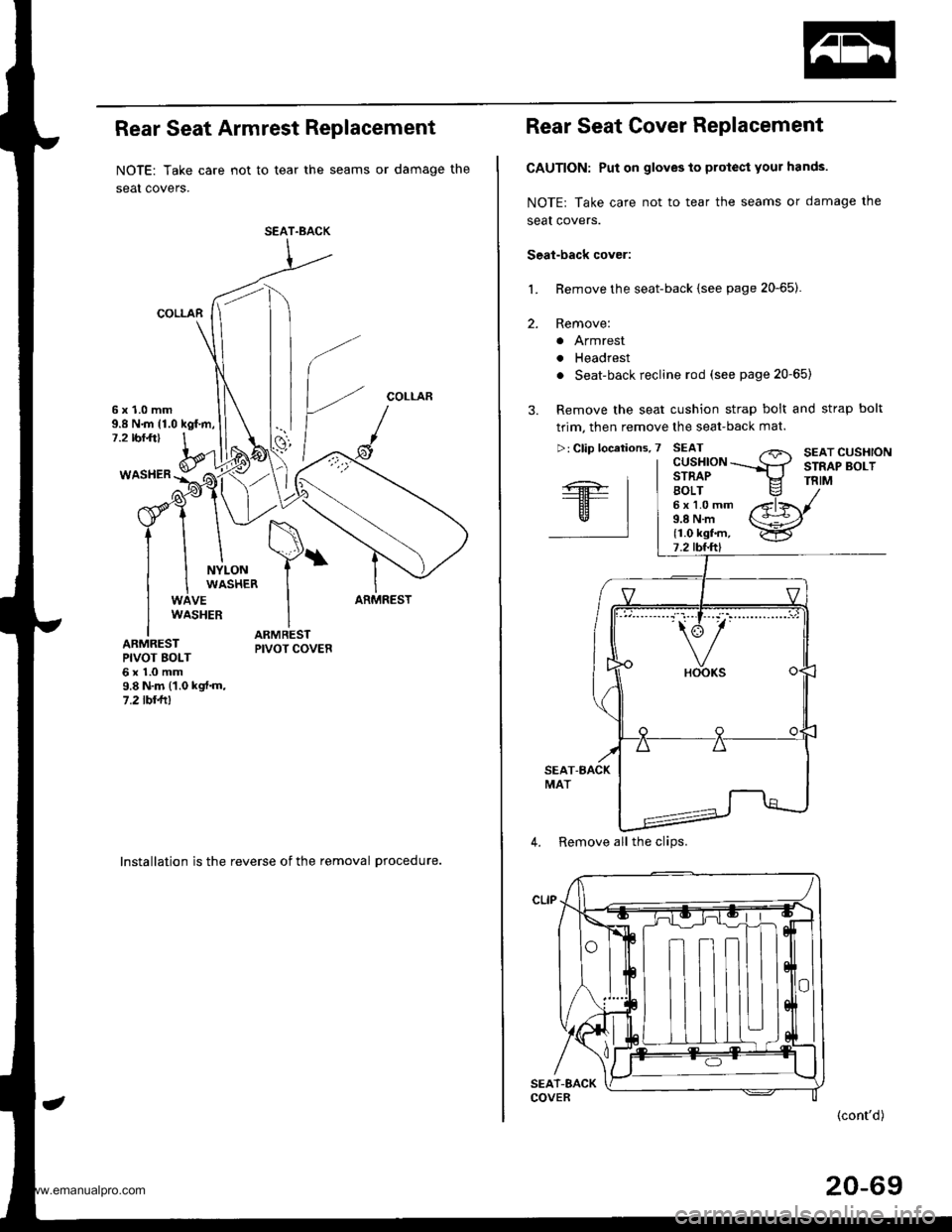
Rear Seat Armrest Replacement
NOTE: Take care not to tear the seams or damage the
seat covers.
COLLAR
COLLAR6x1.0mm9.8 N.m {1.0 kgf.m,7.2 rbr.ft)
WASHER
NYLONWASHER
VEARMRESTWASHER
ARMRESTPIVOT BOLT6x1.0mm9.8 N.m (1.0 kgt.m,7.2lbllll
lnstallation is the reverse of the removal procedure.
SEAT.BACK
Rear Seat Cover Replacement
CAUTION: Put on gloves to protect your hands.
NOTE: Take care not to tear the seams or damage the
seal covers.
Seal-back cover:
Remove the seat-back {see page 20-65).
Remove:
a Armrest
. Headrest
. Seat-back recline rod (see page 20-65)
Remove the seat cushion strap bolt and strap bolt
trim, then remove the seat-back mat.
L
2.
"'---.' t.-r" t-- i,': "" '
4. Remove all the clips.
(cont'd)
20-69
www.emanualpro.com
Page 1051 of 1395
Seats
Rear Seat Cover Replacement (cont'dl
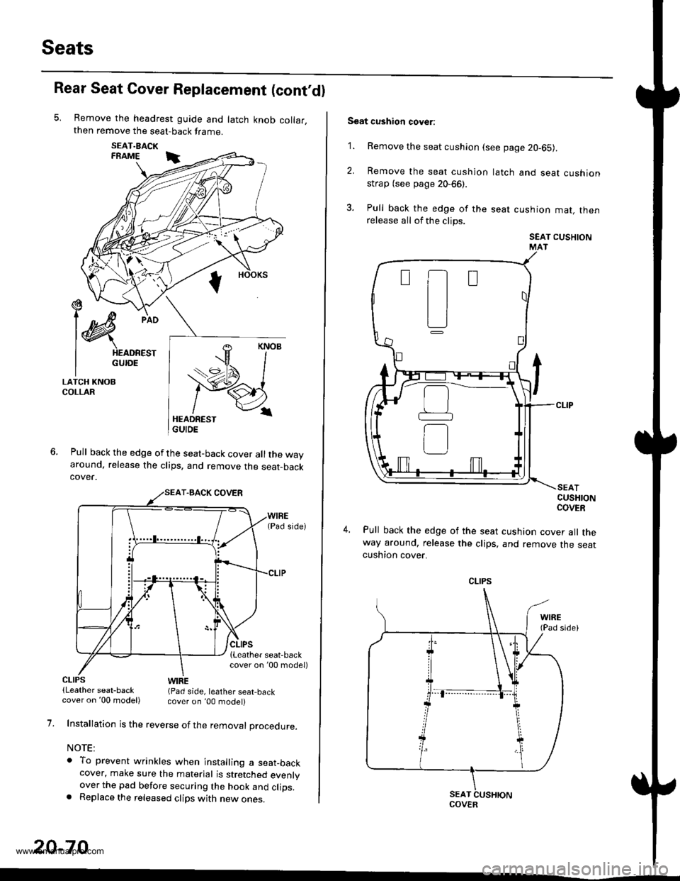
Remove the headrest guide and latch knob collar,then remove the seat-back frame.
SEAT.BACKFRAME i
Pull back the edge of the seat-back cover all the wayaround. release the clips, and remove the seat-backcover.
€ --t)c/
l@
pio
I HEADREST
I GUroE
LATCH KNOBCOLLAR
CLIPS(Leather seat-backWIRE(Pad side, leather seat,back
1.
20-70
cover on '00 model) cover on ,00 model)
Installation is the reverse of the removal procedure.
NOTE:
o To prevent wrinkles when installing a seat_backcover, make sure the material is stretched evenlyover the pad before securing the hook and clips.. Replace the released clips with new ones.
Soat cushion cover:
'1. Remove the seat cushion (see page 20-65).
2. Remove the seat cushion
strap (see page 20-66).
3. Pull back the edge of the
release all of the clips.
latch and seat cushion
seat cushion mat, then
SEAT CUSHIONMAT
CUSHIONCOVER
Pull back the edge of the seat cushion cover all theway around, release the clips, and remove the seatcushton cover.
t-t
tl
L]
CLIPS
COVER
www.emanualpro.com
Page 1067 of 1395
Moldings
Door Moldings Replacement (cont'd)
It the old molding is to be reinstalled:
The following materials and tools are required to repair
the molding.
NOTE: Followthe manufacturer's instructions.
Materials: (Reference)
. Stripe remover
3M 08907
. Stripe adhesive remover
3M 08908
. Adhesive tape
3M Super Automotive Attachment Tape
Tools:
. Protective tape
. Knife or Cutter
. Sponge or Shop towel
. Infrared dryer
. Film
. Plastic putty knife
. Alcohol
CAUTION: Put on gloves to protect your hands,
1. lf necessary, replace any damaged clips on the mold-
ang.
2. Apply the stripe remover evenly to the bonding sur-
face of the body and molding.
3. Cover the bonding surface of the body and molding
with a film, then heat to 104 - 122"F (40 - 50'C) for 5- 10 minutes with an infrared dryer.
NOTE: Use care when heating to prevent deforma-
tion of the body and molding.
4. Carefully scrape the adhesive tape with a plastic
putty knife.
For removal of adhesive tape residue, follow-up with
stripe adhesive remover, then scrape the adhesive
tape with a plastic putty knife.
Remove the protective tape, then clean the bonding
surface with a sponge dampened in alcohol.
NOTE: Make sure the bonding surface is kept free or
water, oil and grease.
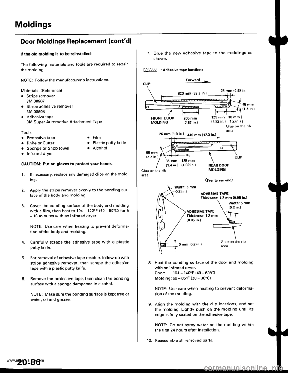
7. Glue the new adhesive tape
snown,
N : Adlesive tape locations
Forwerd L
820 mm 132.3 in.)
FRONTMOLDING
to the moldings as
25 mm {0.98 in.l
45 mm(1.8 in.l
200 mm(7.87 in.)
125 mm
{4.92 in.)30 mm
{1.2 in.}
t'.
Glue on the ribarea,26 mm (1.0 in.) 440 mm 117.3 in.l
35 mm 125 mm
{1.4 in.) {4.92 in.)REAR DOORMOLDING
(Front/rear end)
Width: 5 mm
Heat the bonding surface of the door and molding
with an infrared dryer.
Door: 104 - 140'F (40 - 60'C)
Molding: 68 - 86'F (20 - 30'C)
NOTE: Use care when heating to prevent deforma-
tion of the molding.
Align the molding with the clip locations, and set
the molding. Lightly push on the molding until its
edge is fully seated on the adhesive tape.
NOTE: Oo not spray water on the molding within
the first 24 hours after installation.
Reassemble all removed parts.10.
www.emanualpro.com
Page 1075 of 1395
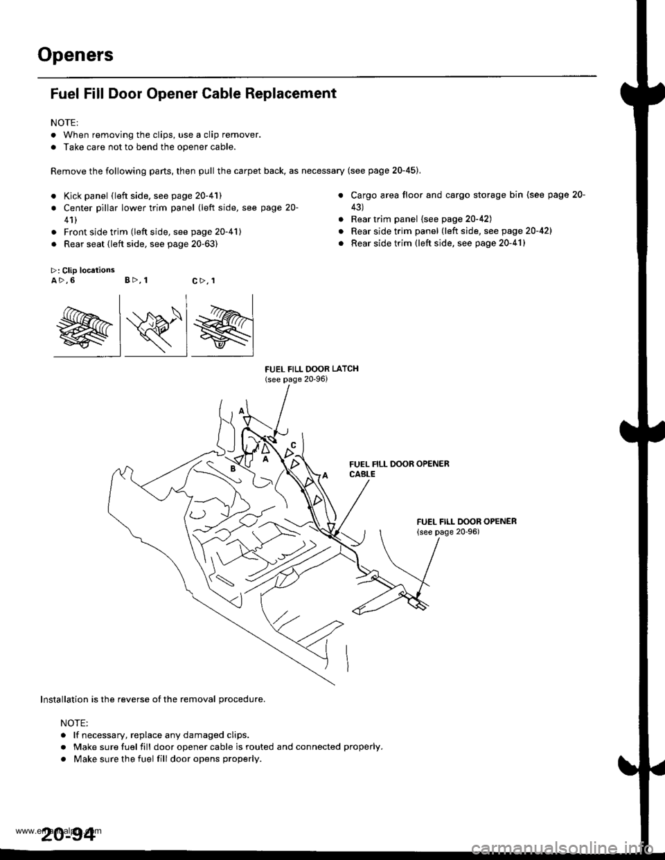
Openers
Fuel Fill Door Opener Cable Replacement
NOTE:
. When removing the clips, use a clip remover.
. Take care not to bend the opener cable.
Remove the following parts, then pull the carpet back, as necessary (see page 20-45),
a
>: Clip locationsA>,6 B>, 1
a
a
FUEL FILL OOOR LATCH(see page 20-96)
Kick panel (left side. see page 20-41)
Center pillar lower trim panel (left side, see page 20-
41)
Front side trim (left side, see page 20-41)
Rear seat (left side, see page 20-63)
Cargo area floor and cargo storage bin (see page
43)
Rear trim panel {see page 20-42)
Rear side trim panel (left side, see page 20-421
Rear side trim (left side, see page 20-41)
FUEL FILL DOOR OPENER
{see page 20-96)
20-
c>,1
@lRlg
Installation is the reverse of the removal procedure.
NOTE:
. lf necessary, replace any damaged clips.
r Make sure fuel fill door opener cable is routed and connected properly.
. Make sure the fuel fill dooropens properly.
www.emanualpro.com
Page 1299 of 1395
IJ
Restraints
Seat Belts .....24-1
Supplemental Restraint SYstem
(sRSl ......'.'. ""'.""".""""24-13
Seat Belts
Component Location Index .'."..'..'-'.' 24'2
Front Seat Belt Replacement '......"'.. 24-3
Rear Seat Belt Replacement ......'.". '.' 24-6
f, - lnspection .....""""""""' 24-9
Child Seat Tether Anchor
lnstallation -'97 - 99 Models ."'."24-10
Child Seat Tether Anchor
Removal/lnstallation
-'00 Model ....'......'.'....'.'.."-'-'."' 24'11
l-
www.emanualpro.com
Page 1300 of 1395
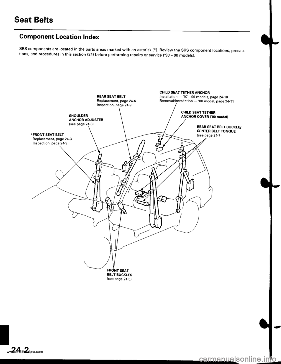
Seat Belts
Component Location Index
SRS components are located in the parts areas marked with an asterisk {*). Review the SRS component locauons, precau-tions, and procedures in this section (24) before performing repairs or service (,98 _ 00 models).
CHILD SEAT TETHEN ANCHORlnstallation -'97 99 models, page 24-10Removal/lnstallation - '00 model, page 24-11
CHILD SEAT TETHERANCHOR COVER ('00 mod€tl
REAR SEAT BELT BUCKLE/CENTER BELT TONGUE(see page 24-7).FRONT SEAT BELTReplacement, page 24 3Inspection, page 24-9
BELT EUCKLES(see page 24 5)
24-2
,--.4
www.emanualpro.com
Page 1301 of 1395
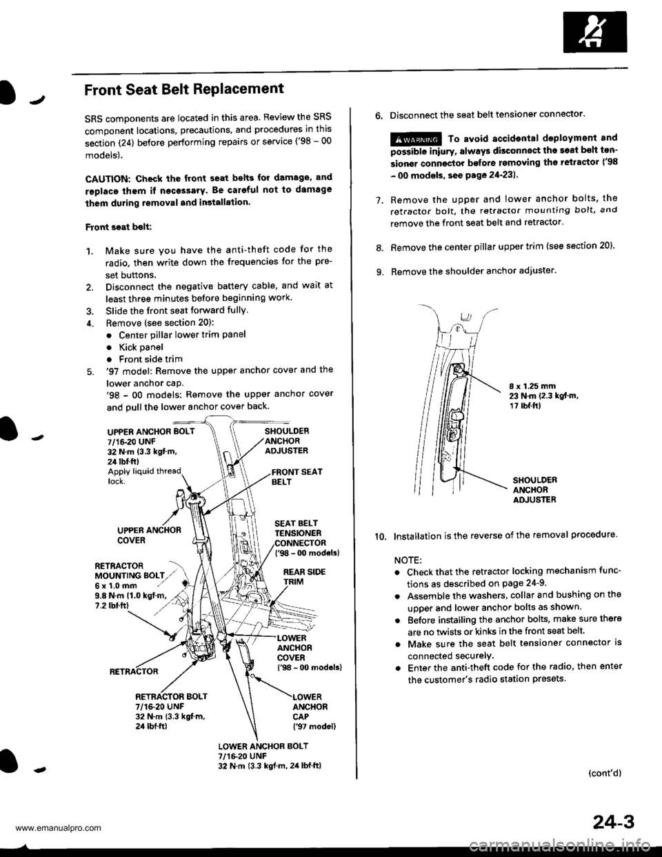
JFront Seat Belt RePlacement
SRS components are located in this area. Review the SRS
component locations, precautions, and procedures in this
section (24) before performing repairs or service ('98 - 00
models).
CAUTION: Check the front seat bslts for damago. and
replaco thom if necessary. Be careful not to damage
them during removal and in3tallation'
Front scat bolt:
1. Make sure you have the anti-theft code for the
radio, then write down the frequencies for the pre-
set buttons.
2. Disconnect the negative battery cable, and wait at
least three minutes before beginning work.
3. Slide the front seat forward fully.
4. Bemove (see section 20):
. Center pillar lower trim Pane
. Kick oanel
. Front side trim
5. '97 model: Remove the upper anchor cover and the
lower anchor caP.'98 - oO models: Remove the upper anchor cover
and pull the lower anchor cover back.
UPPEN ANCHOR BOLT
7/1&20 UNF32 N.m (3.3 kgt'm.24 tbf.ft)
SHOULDERANCHORADJUSTER
Apply liquid threadlock.
9.8 N.m (1.0 kgt.m,?.2 tbtft)
UPPERCOVER
RETRACTORMOUNTING BOLTZ,,Gx1.0mm ./
SEAT BELTTENSIONER
{'98 - 0o modols)
REAR SIDE
ANCHORCOVERl'98 - 00 models)
ANCHORCAP('97 modell
RETRACTOR BOLT7/1&20 UNF32 N.m 13.3 kgt m,24 tbt.ft)
LOWER ANCHOR BOLT?,/1&20 UNF32 N.m {3.3 kgf.m, 2,1 lbf.ftl
o.Disconnect the seat belt tensiongr connector.
@ To avoid accidontal deployment and
possibte inlury, always disconnect the soat bsh ton-
sion€r connoctor bofore rsmoving th6 retractor l'98
- 00 modsls, se€ pa ge 21-231 .
Remove the uDDer and lower anchor boits, the
retractor bolt, the retractor mounting bolt, and
remove the front seat belt and retractor.
Remove the center pillar upper trim (see section 20).
Remove the shoulder anchor adjuster.
7.
9.
8.
I x 1.25 mm23 N.m 12.3 kgt.m,1? tbf.ft)
SHOULDERANCHORADJUSTER
10. lnstallation isthe reverse of the removal procedure.
NOTE:
Check that the retractor locking mechanism func-
tions as described on Page 24-9.
Assemble the washers, collar and bushing on the
uooer and lower anchor bolts as shown.
Eefore installing the anchor bolts, make sure there
are no twists or kinks in the front seat belt.
Make sure the seat belt tensioner connector ls
connected securelv.
Enter the anti-theft code for the radio, then enter
the customer's radio station presets
(cont'd)
24-3
www.emanualpro.com
Page 1304 of 1395
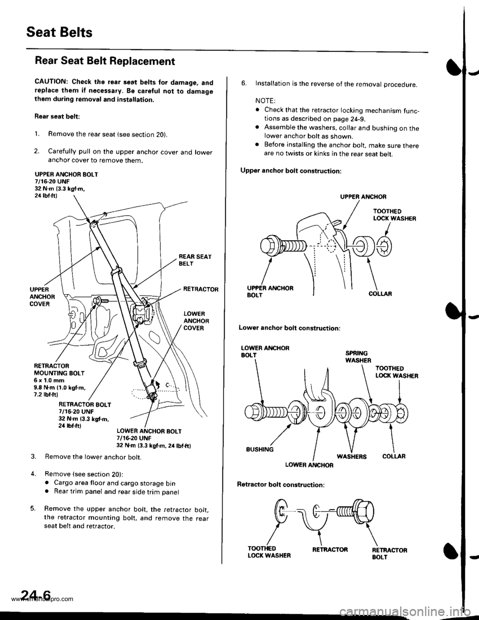
Seat Belts
Rear Seat Belt Replacement
CAUTION: Check the rear s€at belts for damage, andreplace lhem if necessa.y. Be caretul not to damagethem during temoval and installation.
Rear seat belt:
1, Remove the rear seat {see section 20}.
2. Carefully pull on the upper anchor cover and loweranchor cover to remove them.
UPPER ANCHOR BOLT7/16-20 UNF32 N.m 13.3 kg{.m,24 tbt.ft)
REAR SEATBELT
RETRACTOBMOUNTING BOLT6x1.0mm9.8 N.m (1.0 kgt.m.7.2 rbf.ftl
UPPERANCHORCOVER
RETRACTOR
LOWERANCHORCOVER
RETRACIOR EOLT7/16-20 UNF32 N.m {3,3 kgf.m,24 rbr.ft)
3.
4.
LOWER ANCHOF BOLT7/1S20 UNF32 N.m 13.3 kgl.m, 2/r lbf.ftl
Remove the lower anchor bolt.
Remove (see section 20):. Cargo area floor and cargo storage bin. Rear trim panel and rear side trim panel
Remove the upper anchor bolt, the retractor bolt.the retractor mounting bolt, and remove the rearseat belt and retractor.
24-6
,--
6. Installation is the reverse of the removal procedure.
NOTE:
. Check that the retractor locking mechanism func-tions as described on page 24-9.. Assemble the washers, collar and bushing on thelower anchor bolt as shown.. Before installing the anchor bolt, make sure thereare no twists or kinks in the rear seat belt.
Upper anchot bolt construction:
UPPER ANCHOR
TOOTHEOLOCK WASHER
/
A t
ANCHORCOLLAF
Lowel anchor bolt construqtion:
LOWER ANCHORBOLTSPRINGWASHEB
TOOTHEDLOCI( WASHER
BUSHINGWASHERSCOLLAR
LOWER ANCHOR
Rgtractor boll construction:
RETMCTORBOLT
/ r>--->.
f/F\-. (t--nnnllH \
P \v*\
/\\T(X)THEDLOCK WASHERRETRACTOR
www.emanualpro.com
Page 1305 of 1395
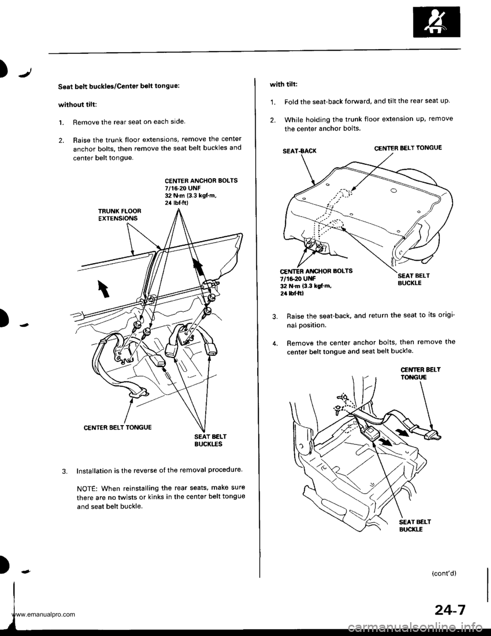
)J
Seat belt buckles/Center belt tongue:
without tilt:
1. Remove the rear seat on each slde.
2. Raise the trunk floor extensions, remove the cenler
anchor bolts, then remove the seat belt buckles and
center belt tongue.
CENTFR ANCHOR BOLTS7/16-20 UNF32 N.m (3.3 kgf.m,2a rbtftt
)
SEAT BELTBUCKITS
lnstallation is the reverse of the removal procedure.
NOTE: When reinstalling the rear seats. make sure
there are no twists or kinks in the center belt tongue
and seat belt buckle.
)
with tilt:
1. Fold the seat-back forward. and tilt the rear seat up
2. While holding the trunk floor extension up, remove
the center anchor bolts
SEAT.BACKCENTER BELT YONGUE
SEAT BELTBUCKLE
Raise the seat-back, and return the seat to its origi-
nal position.
Remove the center anchor bolts, then remove the
center belt tongue and seat belt buckle.
CEiITER AT{CHOR BOLTS
7/1e20 UNF32 N.m {3.3 kgt m,
2r bf.frl
\\
(cont'd)
www.emanualpro.com