Starting HONDA CR-V 1999 RD1-RD3 / 1.G User Guide
[x] Cancel search | Manufacturer: HONDA, Model Year: 1999, Model line: CR-V, Model: HONDA CR-V 1999 RD1-RD3 / 1.GPages: 1395, PDF Size: 35.62 MB
Page 169 of 1395
Oil Seals
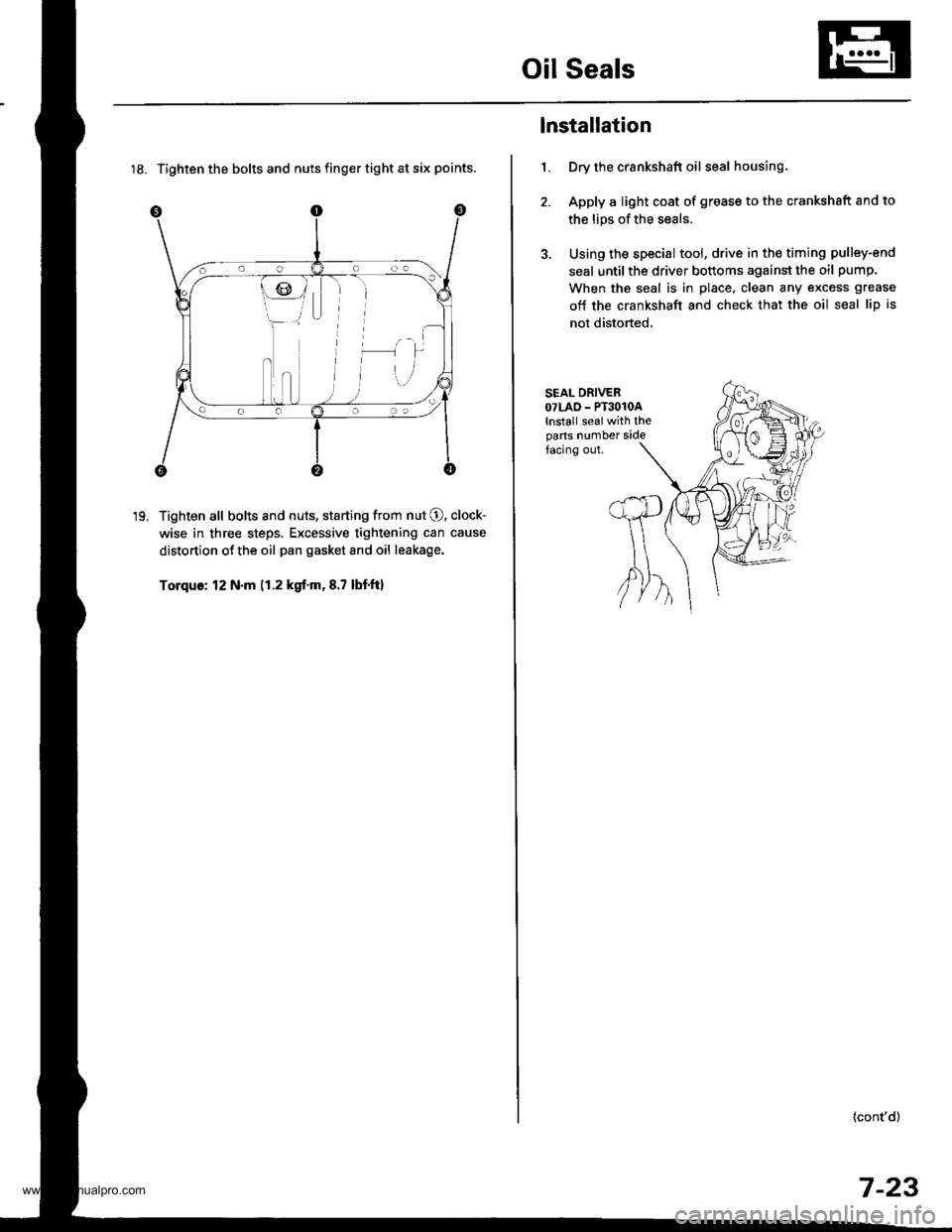
18. Tighten the bolts and nuts finger tight at six points.
Tighten all bolts and nuts, starting from nut O. clock-
wise in three steps. Excessive tightening can cause
distortion ot the oil pan gasket and oil leakage.
Torque: 12 N.m (1.2 kgt.m,8.7 lbtft)
19.
1.
lnstallation
Dry the crankshaft oil seal housing.
Apply a light coat of grease to the crankshsft and to
the lips of the seals.
Using the special tool, drive in the timing pulley-end
seal until the driver bottoms against the oil pump.
When the seal is in place, clean any excess grease
off the crankshaft and check that the oil seal lip is
not distorted,
SEAL DRIVEROTLAD - PT3O1OAlnstall sealwith theparts number sidefacing out.
(cont'd)
7-23
www.emanualpro.com
Page 266 of 1395

Troubleshooting
Troubleshooting Procedures (cont'dl
Symptom Chart
Listed below are symptoms and probable causes for problems that DO NOT cause the Malfunction Indicator Lamp (MlL) tocome on. lf the MIL was reported on, go to page 11-60.Troubleshoot each probable cause in the order listed (from left to right) until the symptom is eliminated,The probable cause and troubleshooting page reference can be found below.
Other Probable Causes for an engine that will not start:- Compression- Intake air leakage- Engine locked up- Timing belt- Starting system- Overheating- Battery
SYMPTOMPROBABLE CAUSE
Engine will not sta rt4, 2,3,5,20, 't5, 1
Hard starting2, 4, 12,17, 14, 't9
Cold fast idle too low7, a,9, 6, 17
Cold fast idle too high7,8,9,11,10
ldle speed fluctuates9,7,8, 't1, 10
Misfire or rough runningTroubleshoot for misfire on pages '11-126, 1|21LOl/\/ power2, 10,11, 13, '17, 18,20
Engine stalls2, 4, 12,1,20,9,5, 't6
Probable Cause List (For the DTC Ch8rt, see page ll-75.)
Probable CausePageSystem
Engine controt ruoaute (ecvtffi'I11-42
I 1-178Fuel oressure
PGM-Fl main relav
lgnition system
Crankshatt Position/Top Dead Center/Cylinder position sensor circuit
Intake Air Temperature (lAT) sensor ctrculr
ldle Air Control (lAC) Vatve
Fast idle thermo valve
ldle speed adjustment
Throttle body
Throftle cable
Manifold Absolute P."""rr"ffi
Throftle Position (TP) sensor
Barometric pressur" (gnno-
Ay'T gear position signal
Brake switch signal
Air Cleaner
Three Way Catalytic Converter (TWC)
Evaporative emission (EVAP) control
Contaminated fuel
1 1- 187
Section 4
5't1-'t31,146
6I '�t-95
711-152
81'l-168
1 1- 169
1011-196'1111-'194
12'1 'l -90
1 1- 103
1411-137
15Section 14
161 1- 166
17r 1-194
181 1,199'1911-203
20
11-64
www.emanualpro.com
Page 282 of 1395

PGM-FI System
System Description
INPUTS
CKP/TDC/CYP Sensor
CKF Sensor
MAP Sensor
ECT Sensor
IAT Sensor
TP Sensor
Primary HO2S
Secondary H02S
vss
KS*5
BARO Sensor
ELD*6
Starter Signal
ALT FR Signal
Air Conditioning Signal
Ay'T Gear Position Signal*1
Baftery Voltage (lGN.1)
Brake Switch Signal
PSP Switch Signal
Fuel Tank Pressuae Sensor*4. *5
Countershaft Speed Sensor*1
Mainshaft Speed Sensor*r
OVER-DRIVE Switch Signal*s
ENGINE CONTROL MODULE (ECM)/
POWERTRAIN CONTROL MODULE (PCM) OUTPUTS
|iuel 1"j""- Th,rhg ""d Drrafr";-l
Et*-.nt"tdt"cont.orl
to,r*,c;;trffi;]
l.----.---:. .Lrgnrnon |lmrng Lonrror I
Ecir/PcM B*k',p Fr""il]
m;"t-ll-r*'io*l
Fuel Injectors
PGM-Fl Main Relay (Fuel Pump)
MIL
IAC Valve
Ay'C Compressor Clutch Relay
Radiator Fan Relay
Condenser Fan Relay
ALT
tcM
EVAP Purge Control Solenoid
Valve
Primary HO2S Heater
Secondary H02S HeaterEVAP Bypass Solenoid Valve*a *5
EVAP Control Canister Vent Shut
DLC
Lock-up Control Solenoid Valve*l
Shift Control Solenoid Valve*1
Ay'T Clutch Pressure Control
Solenoid Valve*1
D4 Indicator Light'1 *3, *a
D Indicator Light,l *5
OVER-DRIVE OFF Indicator
Lighl*t *:
*1: A/T {3:'97 model'2: M/f +4:'98 model*5: '99 - 00 models"6: USA
PGM-Fl System
The PGM-Fl system on this model is a sequential multiport fuel injection system.
Fuel iniecior Timing and Duration
The ECM/PCM contains memories for the basic discharge durations at various engine speeds and manifold pressure. The
basic discharge duration, after being read out from the memory, is further modified by signals sent from various sensors
to obtain the final discharge duration.
ldle Air Control
ldle Air Control Valve (lAC Valve)
When the engine is cold, the Ay'C compressor is on, the transmission is in gear, the brake pedal is depressed, the P/S load
is high, or the alternator is charging, the ECM/PCM controls current to the IAC Valve to maintain the correct idle speed.
lgnition Timing Control
o The ECM/PCM contains memories for basic ionition timing at various engine speeds and manifold air flow rates.
lgnition timing is also adjusted for engine coolant temperature.
. A knock control system was adopted which sets the ideal ig nition timing for the octane rating of the gasoline used.*s
Other Control Funstions
1. Starting Control
When the engine is started. the ECM/PCM provides a rich mixture by increasing fuel injector duration.
2. Fuel Pump Control
. When the ignition switch is initially turned on (ll). the ECMiPCM suppli€s ground to the PGM-FI main relay that
supplies current to the fuel pump for two seconds to pressurize the fuel system.
. When the engine is running, the ECM/PCM supplies ground to the PGM-FI main relay that supplies current to the
fuel oumo.
. When the engine is not running and the ignition is on, the ECM/PCM cuts ground to the PGM-FI main relay which
cuts current to the fuel pump.
1 1-80
www.emanualpro.com
Page 283 of 1395

Fuel Cut-off Control
. During deceleration with the throttle valve closed, current to the fuel injectors iscutoffto improvefuel economyat
speeds over 970 rpm ('97 - 98 models), 920 rpm ('99 - 00 modelsl.
. Fuel cut-off action also takes place when engine speed exceeds 6,500 rpm ('97 - 98 models), 6900 rpm ('99 - 00
models), regardless of the position of the throttle valve, to protect the engine from over-rewing.
With Ay'T model. the PCM cuts the fuel at engine speeds over 5,000 rpm when the vehicle is not moving.*'�
4,./C Comoressor Clutch Relav
When the ECM/PCM receives a demand for cooling from the air conditioning system, it delays the compressor from
being energized, and enriches the mixture to assure a smooth transition to the Ay'C mode.
Evaporative Emission (EVAP) Purge Control Solenoid Valve
When the engine coolant temperature is above 154"F (68'C), the ECM/PCM controls the EVAP purge control solenoid
valve which controls vacuum to the EVAP purge control canister,
Alternator Control
The system controls the voltage generated at the alternator in accordance with the electrical load and driving mode.
which reduces the engine load to improve the fuel economy.
PCM Fail-saf e/Back-up Functions
1. Fail-safe Function
When an abnormality occurs in a signal from a sensor, the ECM/PCM ignores that signal and assumes a pre-pre
grammed value for that sensor that allows the engine to continue to run.
2. Back-up Function
When an abnormality occurs in the ECM/PCM itself, the fuel injectors are controlled by a back-up circuit independent
of the system in order to permit minimal driving.
3. Self-diagnosis Function IMalfunction Indicator Lamp (MlL)l
When an abnormality occurs in a signal from a sensor, the ECM/PCM supplies ground for the MIL and stores the DTC
in erasable memory. When the ignition is initially turned on {ll), the ECM/PCM supplies ground for the MIL for two
seconds to check the MIL bulb condition.
4. Two Trio Detection Method
To prevent false indications, the Two Trip Detection Method is used for the HO2S*1, fuel metering-related. idle control
system, ECT sensor and EVAP control system self-diagnostic functions. When an abnormality occurs, the ECM/PCM
stores it in its memory. When the same abnormality recurs after the ignition switch is turned OFF and ON (ll) again,
the ECM/PCM informs the driver by lighting the MlL. However, to ease troubleshooting, this function is cancelled
when you jump the service check connector, The MIL will then blink immediately when an abnormality occurs.
5. Two (or Three) Driving Cycle Detection Method {'97 model)
A "Driving Cycle" consists of starting the engine, beginning closed loop operation, and stopping the engine. lf misfir-
ing that increases emissions or EVAP control system malfunction is detected during two consecutive driving cycles.
or TWC deterioration is detected during three consecutive driving cycles, the ECM/PCM turns the MIL on. However, to
ease troubleshooting, this function is cancelled when you jump the service check connector. The MIL will then blink
immediately when an abnormality occurs.
*1: '97 - 98 models*2: '99 - 00 models
5.
www.emanualpro.com
Page 405 of 1395
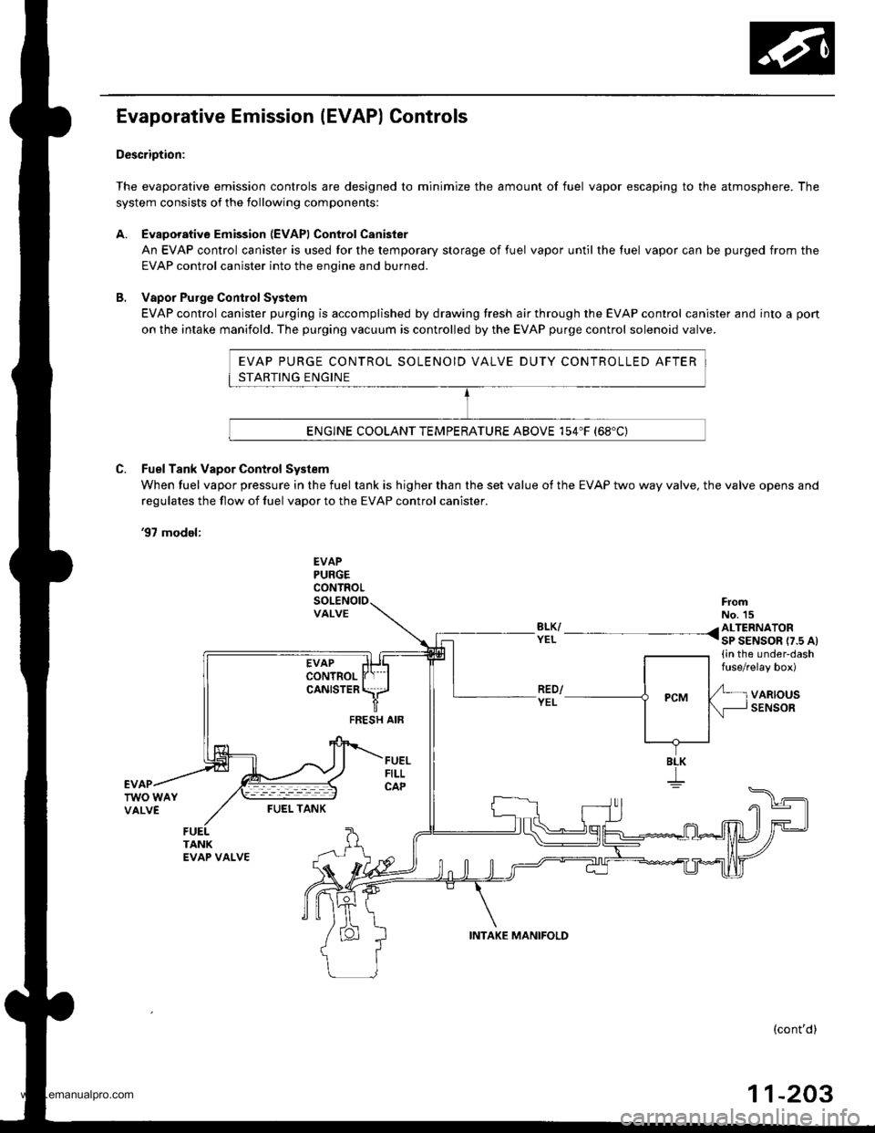
EVAP PURGE CONTROL SOLENOID VALVE DUTY CONTROLLED AFTER
STARTING ENGINE
ENGINE COOLANT TEMPERATURE ABOVE 154"F (68'C)
Evaporative Emission (EVAP) Controls
Description:
The evaporative emission controls are designed to minimize the amount of fuel vapor escaping to the atmosphere. The
system consists of the following components:
A. Evaporative Emission (EVAPI Control Canister
An EVAP control canister is used for the temporary storage of fuel vapor until the luel vapor can be purged from the
EVAP control canister into the enqine and burned.
B. Vapor Purge ConirolSystem
EVAP control canister purging is accomplished by drawing fresh air through the EVAP control canister and into a pon
on the intake manifold. The purging vacuum is controlled by the EVAP purge control solenoid valve.
C. Fuel Tank Vapor Control System
When fuel vapor pressure in the fuel tank is higher than the set value of the EVAP two way valve, the valve opens and
regulates the flow ot fuel vapor to the EVAP control canister.
'97 model:
EVAPPURGECONTROL
VALVEFromNo. 15BLK/ /ALTERNATORYEL I sP SENSOR r7.s At(in the under-dashfuse/relay box)
VARIOUSSENSORFEESH AIF
BLK
I
FUEI- TANK
(cont'd)
11-203
INTAKE MANIFOLD
www.emanualpro.com
Page 443 of 1395
Transfer Assembly
lnspection
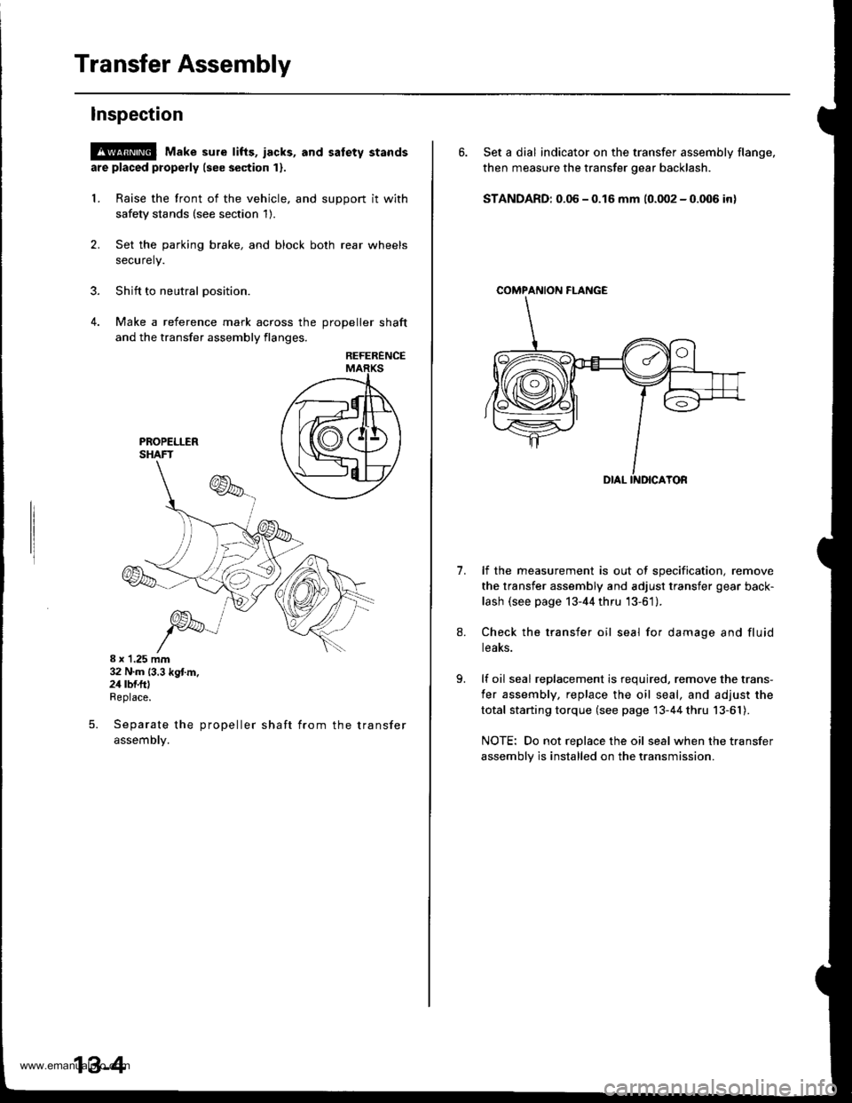
@ Make sure tifts, iacks, and satety stands
are placed properly (see section 1).
L Raise the front of the vehicle, and support it with
safety stands (see section 1).
2. Set the parking brake, and block both rear wheels
securely.
3. Shift to neutral oosition.
4. Make a reference mark across the DroDeller shaft
and the transfer assembly flanges,
REFERENCE
8 x 1.25 mm32 N.m (3.3 kg{.m.24 rbf.ftlReplace.
Separate the propeller shaft from the transfer
assemDty.
5.
13-4
6. Set a dial indicator on the transfer assembly flange,
then measure the transfer gear backlash.
STANDARD: 0.06 - 0.16 mm (0.002 - 0.006 in)
COMPAf{ION FI-ANGE
1.lf the measurement is out of specification, remove
the transfer assembly and adjust transfer gear back-
lash (see page 13-44 thru '13-61).
Check the transfer oil seal for damage and fluid
teaKs.
lf oil seal replacement is required, remove the trans-
fer assembly, replace the oil seal, and adjust the
total starting torque (see page 13-44 thru 13-61).
NOTE: Do not replace the oil seal when the transfer
assembly is installed on the transmission.
www.emanualpro.com
Page 480 of 1395
Tapered Roller Bearing Preload Adiustment
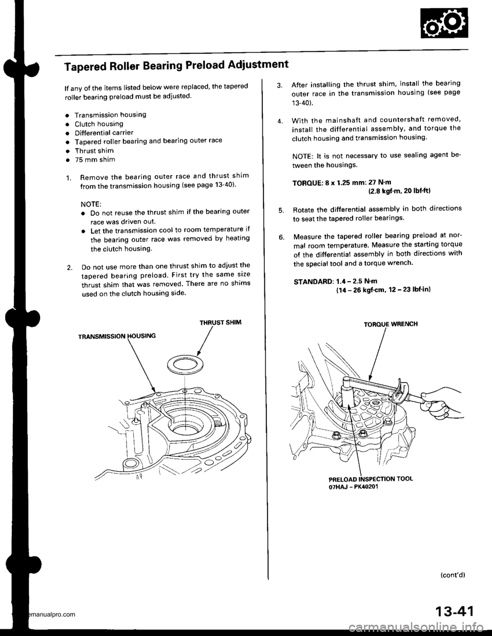
lf any oJ the items listed below were replaced, the tapered
roller bearing preload must be adjusted.
. Transmission housing
. Clutch housing
. Differential carrier
o Tapered roller bearing and bearing outer race
. Thrust shim
. 75 mm sham
1. Remove the bearing outer race and thrust shim
from the transmission housing (see page 13-40)'
NOTE:
. Do not reuse the thrust shim if the bearing outer
race was driven out.
. Let the transmission cool to room temperature il
the bearing outer race was removed by heating
the clutch housing.
2. Do not use more than one thrust shim to adjust the
tapered bearing preload. First try the same size
thrust shim that was removed. There are no shims
used on the clutch housing side
SHIMTHRUST
/A
After installing the thrust shim, install the bearing
outer race in the transmission housing (see page
13-40).
With the mainshaft and countershaft removed,
install the differential assembly, and torque the
clutch housing and transmission housing.
NOTE: lt is not necessary to use sealing agent be-
tween the housings.
TOBOUE; 8 x 1.25 mm: 27 N'm(2.8 kgf'm, 20 lbt'ftl
Rotate the differential assembly in both directions
to seat the tapered roller bearings.
Measure the tapered roller bearing preload at nor-
mal room temperature. Measure the starting torque
of the differential assembly in both directions with
the special tool and a torque wrench.
STANDAFD: 1.4 - 2.5 N'm
{1/r - 26 kgf'cm, 12 - 23 lbf in)
(cont'd)
4.
5.
07HAJ - PK4020'�1
13-41
www.emanualpro.com
Page 484 of 1395
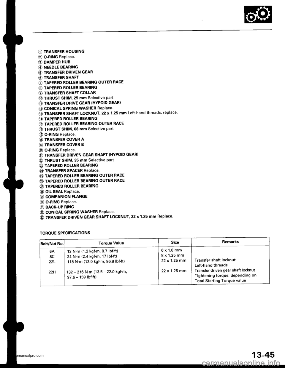
O TRANSFER HOUSING
@ O-RING Replace.
O DAMPER HUB
G) NEEDLE BEARING
G) TRANSFER DRIVEN GEAR
G) TRANSFER SHAFT
O TAPERED ROLLER BEARING OUTER RACE
@ TAPERED ROLLER BEARING
€) TRANSFER SHAFT COLLAR
@ THRUST SHIM, 25 mm selective part
6D TRANSFER DRIVE GEAR (HYPOID GEAR)
@ CONICAL SPRING WASHER RePlace
GD TRANSFER SHAFT LOCKNUT.22 x 1.25 mm Left-hand threads, replace'
E) TAPERED ROLLER BEARING
@ TAPERED ROLLER BEARING OUTER RACE
@ THRUST sHlM. 68 mm selective part
O o.RlNG Replace.
@ TRANSFER COVER A
GD TRANSFER COVER B
@ O-RING Replace.
€) TRANSFER DRIVEN GEAR SHAFT (HYPOID GEAR}
@ THRUST SHIM, 35 mm Selective Part
@ TAPERED ROLLER BEARING
@ TRANSFEB SPACEB RepIace.
@ TAPERED ROLLER BEARING OUTER RACE
@ TAPERED ROLLER BEARING OUTER RACE
@) TAPERED ROLLER BEARING
@ olL SEAL Replace.
@ COMPANION FLANGE
@ O-RING Replace.
@ BACK-UP RING
@ coNtcAL SPRING WASHEB Replace.
(o TRANSFER DRIVEN GEAR SHAFT LOCKNUT,22 x 1.25 mm Replace.
TOROUE SPECIFICATIONS
Boh/Nut No.Torque ValueSizeRemarks
6A
8C
22L
22H
12 N.m (1.2 kgf.m.8.7 lbf.ft)
24 N.m {2.4 kgf.m, 17 lbf'ft)
118 N.m (12.0 kgf.m, 86.8 lbf'ftl
132 - 216 N.m (13.5 - 22.0 kgf'm,
97.6 - 159 lbf.ft)
6x1.0mm
8 x 1.25 mm
22 x 1 ,25 mm
22 x 1 .25 mm
Transfer shaft locknut:
Lett-hand threads
Transfer driven gear shaft locknut
Tightening torque: dePending on
Total Starting Torque vaiue
13-45
www.emanualpro.com
Page 485 of 1395
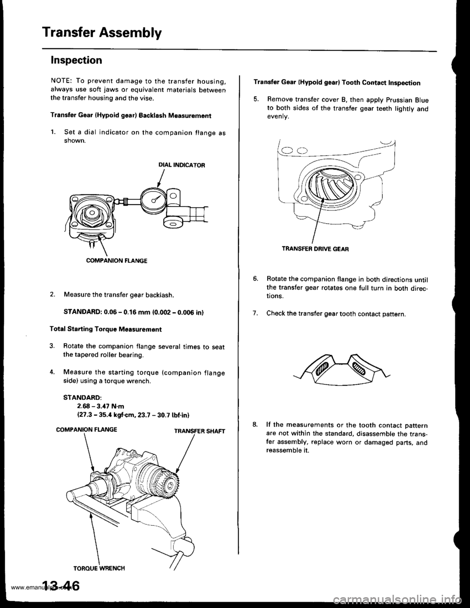
Transfer Assembly
Inspection
NOTE: To prevent damage to the transfer housing,
always use soft jaws or equivalent materials between
the transfer housing and the vise.
Transter Gaar (Hypoid goar) Backlssh M€asurement
1. Set a dial indicator on the companion flange asshown.
2. Measure the transfer gear backlash.
STANDARD: 0.06 - 0.16 mm {0.002 - 0.006 in}
Total Sta.ting Torquo Msasuremont
3. Rotate the companion flange several times to seatthe tapered roller bearing.
4. Measure the starting torque (companion flange
side) using a torque wrench.
STANDARD:
2.68 - 3.47 N.m
{27.3 - 35.4 kgf.cm.23.7 - 30.7 tbt.in)
DIAL INDICATOR
COMPANION FLANGE
13-46
Transfer Gear lHypoid gearl Tooth Contaqt Insp€ction
5. Remove transfer cover B, then apply Prussian Blueto both sides of the transler gear teeth lightly andevenlv.
Rotate the companion flange in both directions untilthe transfer gear rotates one full tuln in both direc-tions.
Check the transfer gear tooth contact pattern.7.
lf the measurements or the tooth contact Datternare not within the standard. disassemble the trans-fer assembly, replace worn or damaged parts, andreassemble it.
TRANSFER DRIVE GEAR
www.emanualpro.com
Page 491 of 1395
Transfer Assembly
Reassembly
Note these items during reassembly:. While reassembling the transfer assembly:- Check and adjust the transfer gear tooth contact.- Measure and adjust the transfer gear backlash.- Check and adjust the tapered roller bearing start-Ing rorque.
. Coat all parts with MTF during reassembly.. Replace the tapered roller bearing and the bearingouter race as a set if either part is replaced.. Replace the transfer drive gear and the transfer dri-ven gear shaft as a set if either part is replaced,
Outline of Assembly
1.Select the 35 mm thrust shim.
Perform this procedure if the transler driven gear
shaft or the tapered roller bearing on the transferdriven gear shaft is replaced.
Preassemble the parts to check and adjust transfergear backlash and transfer gear tooth contact.
Disassemble the parts, then assemble the transferdriven gear shaft and its related parts.
4. Measure and adjust the staning torque of the trans-fer driven gear shaft tapered roller bearing.
5. Assemble the transfer shaft and jts related parts.
6. Measure and adjust the total starting torque.
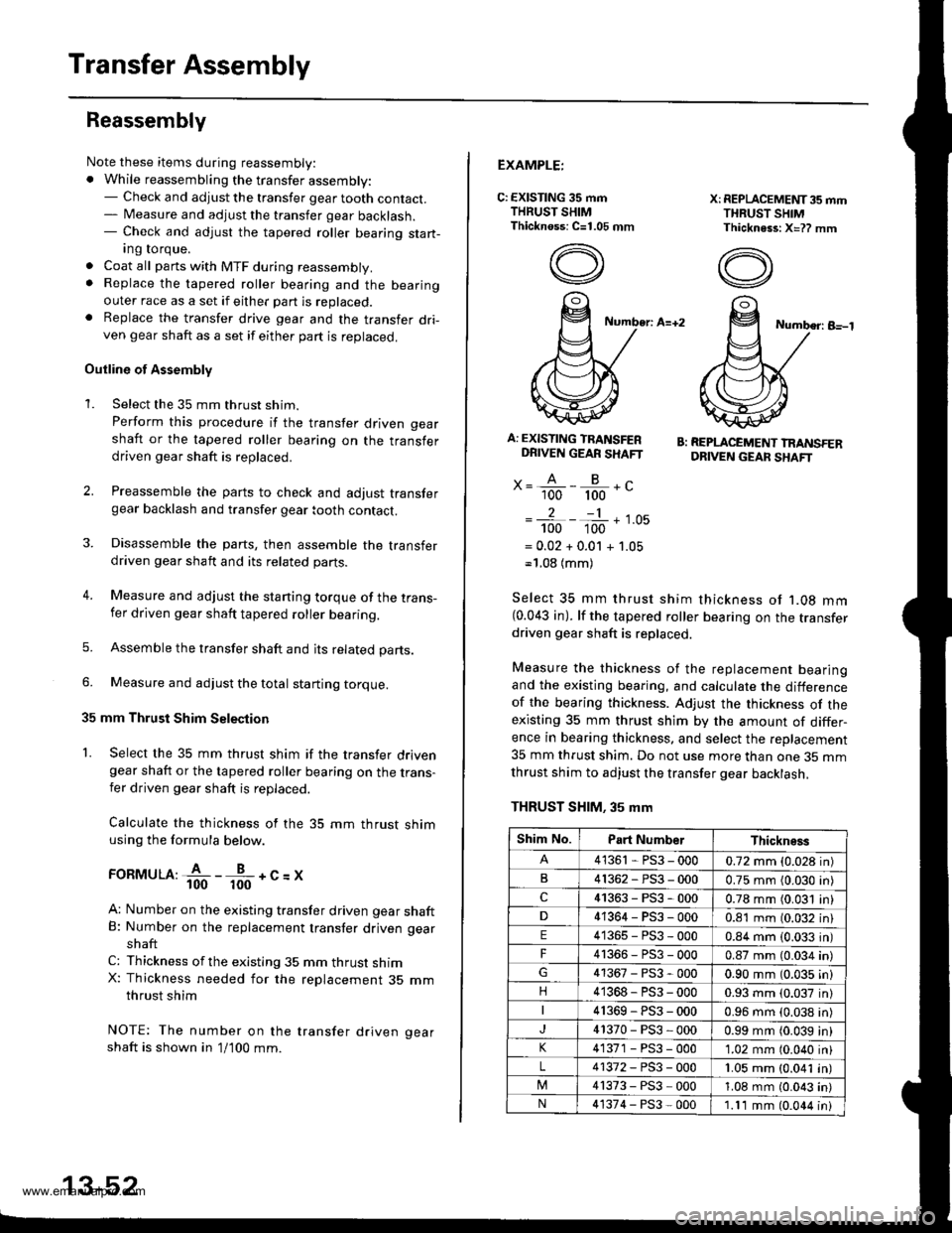
35 mm Thrust Shim Seleqtion
1. Select the 35 mm thrust shim if the transfer drivengear shaft or the tapered roller bearing on the trans-fer driven gear shaft is replaced.
Calculate the thickness of the 35 mm thrust shimusing the formula below.
ronrvruu:fi--fr-+c=x
A: Number on the existing transfer driven gear shaftB: Number on the replacement transfer driven gear
shaft
C: Thickness ofthe existing 35 mm thrust shimX: Thickness needed for the replacement 35 mmthrust shim
NOTE: The number on the transfer driven gear
shaft is shown in 1/100 mm.
2.
3.
13-52
EXAMPLE:
C: EXISTING 35 mmTHRUST SHIMThicknoss: C=1.05 mm
X: REPLACEMET{T35 mmTHRUST SHIMThickness: X=?? mm
Number: A=+2Number: B-l
A: EXISTING TRANSFERDRIVEN GEAR SHAFT
x= A - B -.'- 100 100 -
2-1
100 100 '-
= 0.02 + 0.01 + 1.05-'1.08 (mm)
B: REPLACEMENT TRANSFERDRIVEN GEAF SHAFT
Select 35 mm thrust shim thickness ot '1.08 mm(0.043 in). lf the tapered roller bearing on the transferdriven gear shaft is replaced.
Measure the thickness of the replacement bearingand the existing bearing, and calculate the differenceof the bearing thickness. Adjust the thickness of theexisting 35 mm thrust shim by the amount of differ-ence in bearing thickness. and select the replacement
35 mm thrust shim. Do not use more than one 35 mmthrust shim to adjust the transfer gear backlash,
THRUST SHIM. 35 mm
Shim No.Part NumberThickness
41361 - PS3 - 0000.72 mm (0.028 in)
B41362-PS3-0000.75 mm (0.030 in)
c41363-PS3-0000.78 mm (0.031 in)
41364-PS3-0000.81 mm (0.032 in)
E41365-PS3-0000.84 mm (0.033 in)
F4r366-PS3-0000.87 mm (0.034 in)
41367-PS3-0000.90 mm (0.035 in)
n41368-PS3-0000.93 mm (0.037 in)
41369-PS3-0000.96 mm {0.038 in)
41370-PS3-0000.99 mm (0.039 in)
41371 - PS3 - 0001.02 mm (0.040 in)
L41372-PS3-0001.05 mm (0.041 in)
41373-PS3-0001.08 mm (0.043 in)
N41374-PS3-0001.11 mm (0.044 in)
www.emanualpro.com