countershaft HONDA CR-V 1999 RD1-RD3 / 1.G User Guide
[x] Cancel search | Manufacturer: HONDA, Model Year: 1999, Model line: CR-V, Model: HONDA CR-V 1999 RD1-RD3 / 1.GPages: 1395, PDF Size: 35.62 MB
Page 467 of 1395
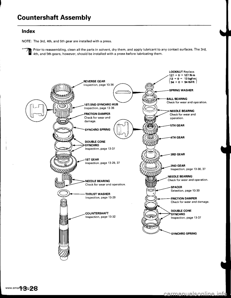
Countershaft Assembly
Index
NOTE:
3
The 3rd, 4th. and sth gear are installed with a press.
Prior to reassembling, clean all the parts in solvent, dry them, and apply lubricant to any contact surfaces. The 3rd,
4th, and sth gears, however. should be installed with a press before lubricating them.
LOCKNUT Replace.127-o-127N.m
113-0- 13kstmi
\94-0- 9.trbtft /
IST/2ND SYNCHRO HUBInspection, page 13 36
Check lor wear anddamage.
THRUST WASHERInspection, page 13-29
DAMPER
WASHER
AEARINGCheck for wear and ooeration.
BEARINGCheck for wear andoperation.
GEAR
4TH GEAR
3RD GEAR
GEAR
SPNING
DOUBI.f CONE
Inspection, page 13-37
1ST GEARInspection, page 13 29,37
BEARINGCheck tor wear and operation.
Inspection, page 13-30, 37
NEEDLE BEARINGCheck for wear and oPeration
SPACERSelection, page 13-30
DAMPERCheck for wear and damage.
DOUBLE CONE
Inspection, page 13-37
SPRING
www.emanualpro.com
Page 469 of 1395
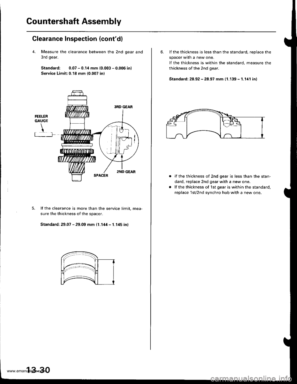
Countershaft Assembly
Clearance Inspection (cont'dl
4. Measure the clearance between the 2nd qear and
3rd gear.
Standard: 0.07 - 0.1,1 mm (0.003 - 0.006 inl
Service Limit:0.18 mm (0.007 inl
FEET.ERGAUGE
!t .�-]�
lf the clearance is more than the service limit. mea-
sure the thickness of the spacer.
Standard: 29.07 - 29.09 mm (l.14il - 1.145 inl
13-30
6. lf the thickness is less than the standard, reDlace the
spacer wrln a new one.
lf the thickness is within the standard, measure the
thickness of the 2nd gear.
Standald: 28.92 - 28.97 mm (1.139 - 1.141 in)
lf the thickness of 2nd gear is less than the stan-
dard, replace 2nd gear with a new one.
lf the thickness of lst gear is within the standard,
replace 1sv2nd synchro hub with a new one.
www.emanualpro.com
Page 470 of 1395
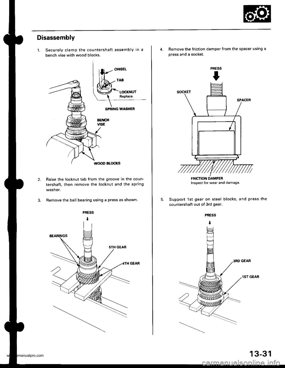
Disassembly
1.
2.
Securely clamp the countershaft assembly in a
bench vise with wood blocks.
SPRIiIG WASHEF
BETICHvtsE
W(X)D BLOCKS
Raise the locknut tab from the groove in the coun-
tershaft, then remove the locknut and the spring
washer.
Remove the ball bearing using a press as shown.
CHISEL
4. Remove the Jriction damper from the spacer using a
press and a socket.
Support lst gear on steel blocks, and press the
countershaft out of 3rd gear.
PRESS
t
5.
PRESS
I
3RD GEAR
1ST GEAR
FRICTION DAMPERInspect lor wear and damage.
13-31
www.emanualpro.com
Page 471 of 1395
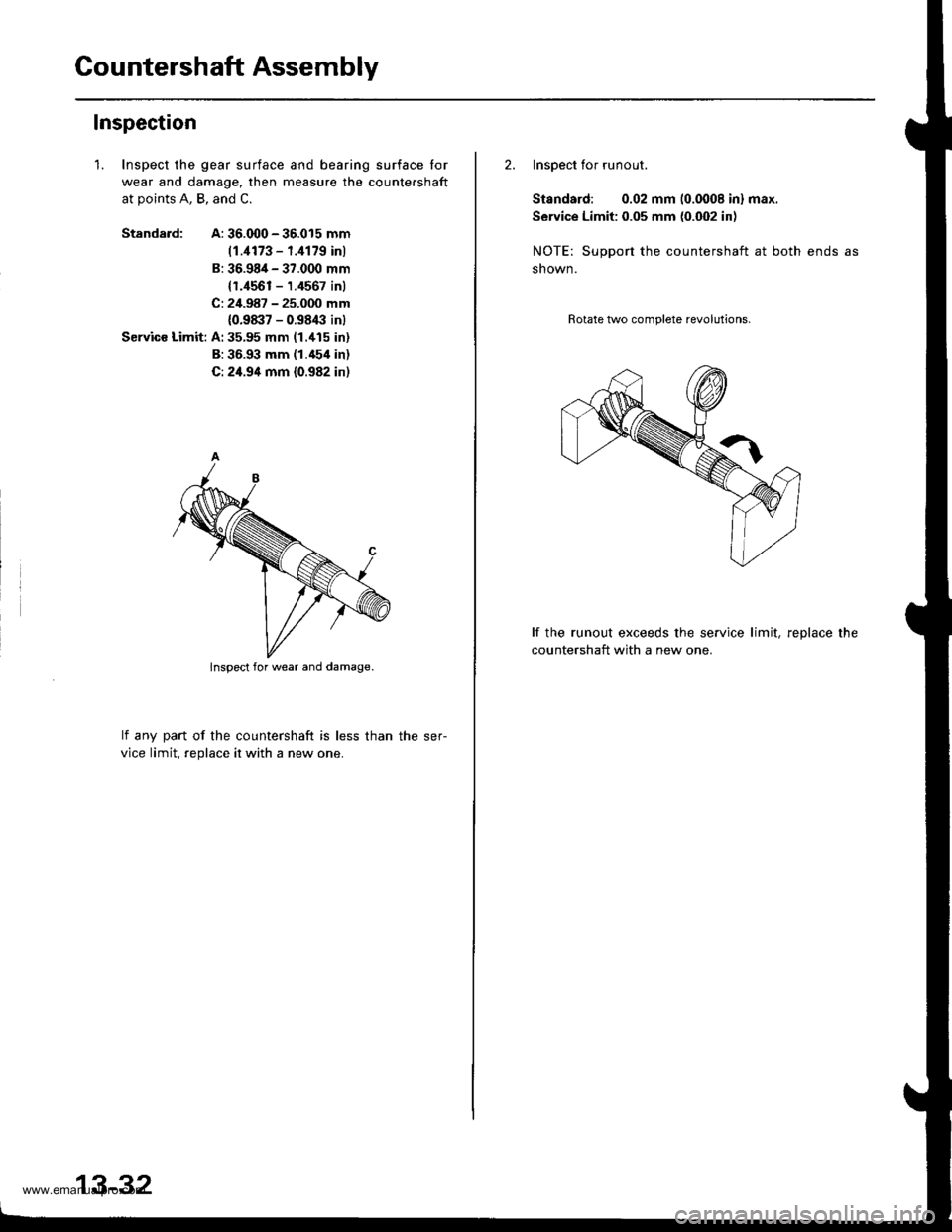
Countershaft Assembly
Inspection
1. Inspect the gear surface and bearing surface Ior
wear and damage, then measure the countershaft
at points A, B, and C.
Standa.d:A: 36.000 - 36.015 mm
11.,1173 - f.ill79 inl
B: 36.98/t - 37.000 mm
{r.4561 - 1.4567 inl
C: 24.987 - 25.000 mm
{0.98:17 - 0.9843 inl
Servics Limit: A:35,95 mm (1.'115 in)
B: 36.93 mm (1.454 in)
C: 24.94 mm (0.982 in)
lf anv part of the countershaft is less than the ser-
vice limit. reolace it with a new one.
lnspect for wear and damage.
13-32
2. Inspect for runout.
Standard: 0.02 mm 10.0008 inl max.
Service Limit: 0.05 mm {0.002 inl
NOTE: Support the countershaft at both ends as
shown.
Rotate two complete revolutions.
lf the runout exceeds the service limit, reDlace the
countershaft with a new one.
www.emanualpro.com
Page 472 of 1395
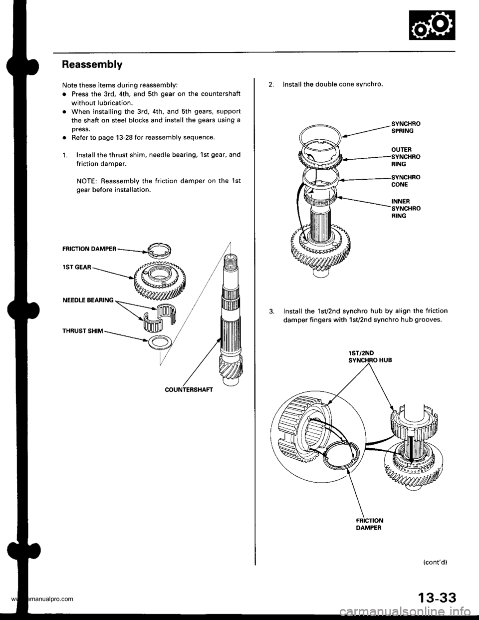
Reassembly
Note these items during reassembly:
. Press the 3rd, 4th, and sth gear on the countershaft
without lubrication.
. When installing the 3rd, 4th. and sth gears, suppon
the shaft on steel blocks and install the gears using a
press.
. Refer to page 13-28 for reassembly sequence.
1. Install the thrust shim, needle bearing, 1st gear, and
friction damper.
NOTE: Reassembly the friction damper on the lst
gear before installation.
rnrcrroru orn,leen ----.-4O)
lST GEAR
NEEDLE BEARING
THRUST SHIM
2. Install the double cone synchro.
3. Install the 1sv2nd synchro hub by align the friction
damper fingers with 1svznd synchro hub grooves.
(cont'd)
OUTER
lST/2ND
13-33
www.emanualpro.com
Page 473 of 1395
Countershaft Assembly
Reassembly (cont'dl
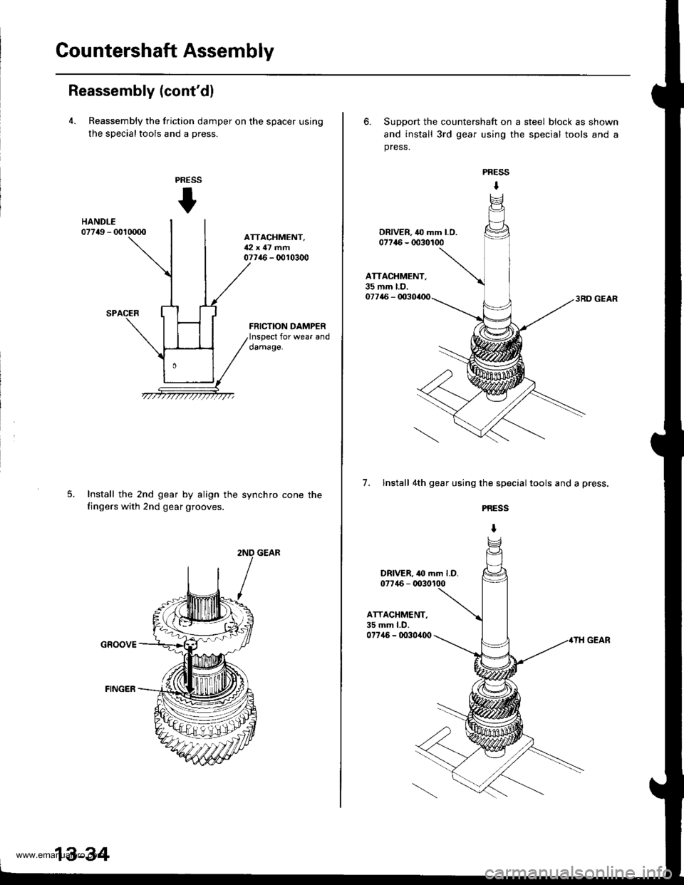
4. Reassembly the friction damper on the spacer using
the sDecialtools and a Dress.
PRESS
t
ATTACHMENT,U2t 47 mfi07716 - 0010300
FRICTION DAMPERInspect for wear anddamage.
Install the 2nd gear by align the
fingers with 2nd gear grooves.
synchro cone the
GROOVE
13-34
6. Support the countershaft on a steel block as shown
and install 3rd gear using the special tools and a
press.
3RO GEAR
7. lnstall 4th gear using the special tools and a press.
PRESS
I
PRESS
t
ATTACHMENT,35 mm LD.07746 - 0030,100
www.emanualpro.com
Page 474 of 1395
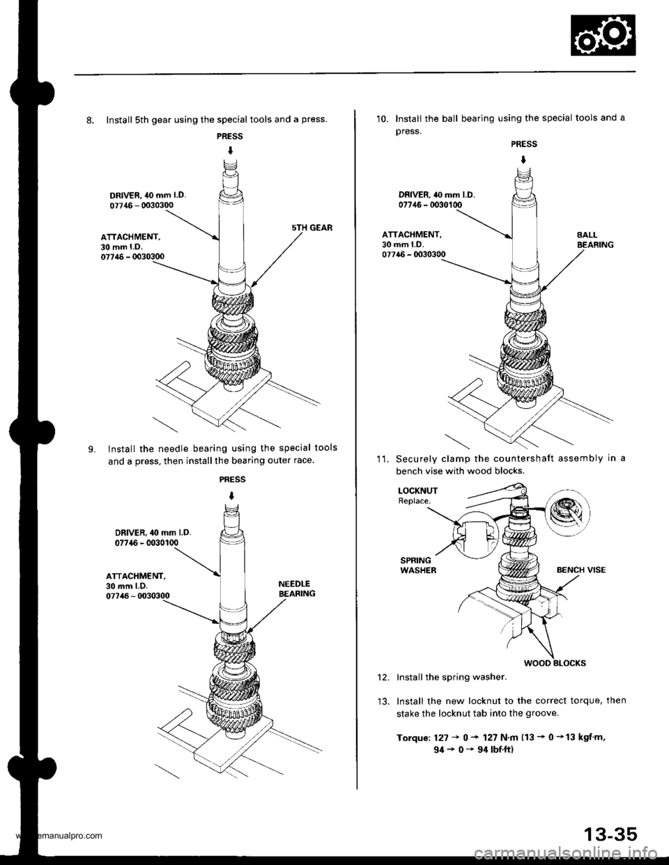
8. Install sth gear using the special tools and a press.
PRESS
I
DRIVER, 40 mm l.D.
07715 - 0030300
ATTACHMENT,30 mm LD.077,16 - 0030300
LInstall the needle bearing using the special tools
and a press, then installthe bearing outer race
PRESS
I
DRIVER. 40 mm l.D.077{6 - 0030100
ATTACHMENT,30 mm l.D.07746 - 0030300
NEEDLEBEASING
10. Install the ball bearing using the special tools and a
press.
PRESS
I
DRIVER. 40 mm LD.07746 - 0030100
ATTACHMENT,30 mm LD.077a6 - 0030300
11.Securely clamp the countershaft assembly in
bench vise with wood blocks.
LOCKNUTReplace.
Install the spring washer.
Install the new locknut to the correct torque, then
stake the locknut tab into the groove.
Torque: 127 + 0 + 127 N.m 113 - 0 +13 kgf.m,
94+0-94|bf.ft)
12.
wooD slocKs
13-35
www.emanualpro.com
Page 480 of 1395
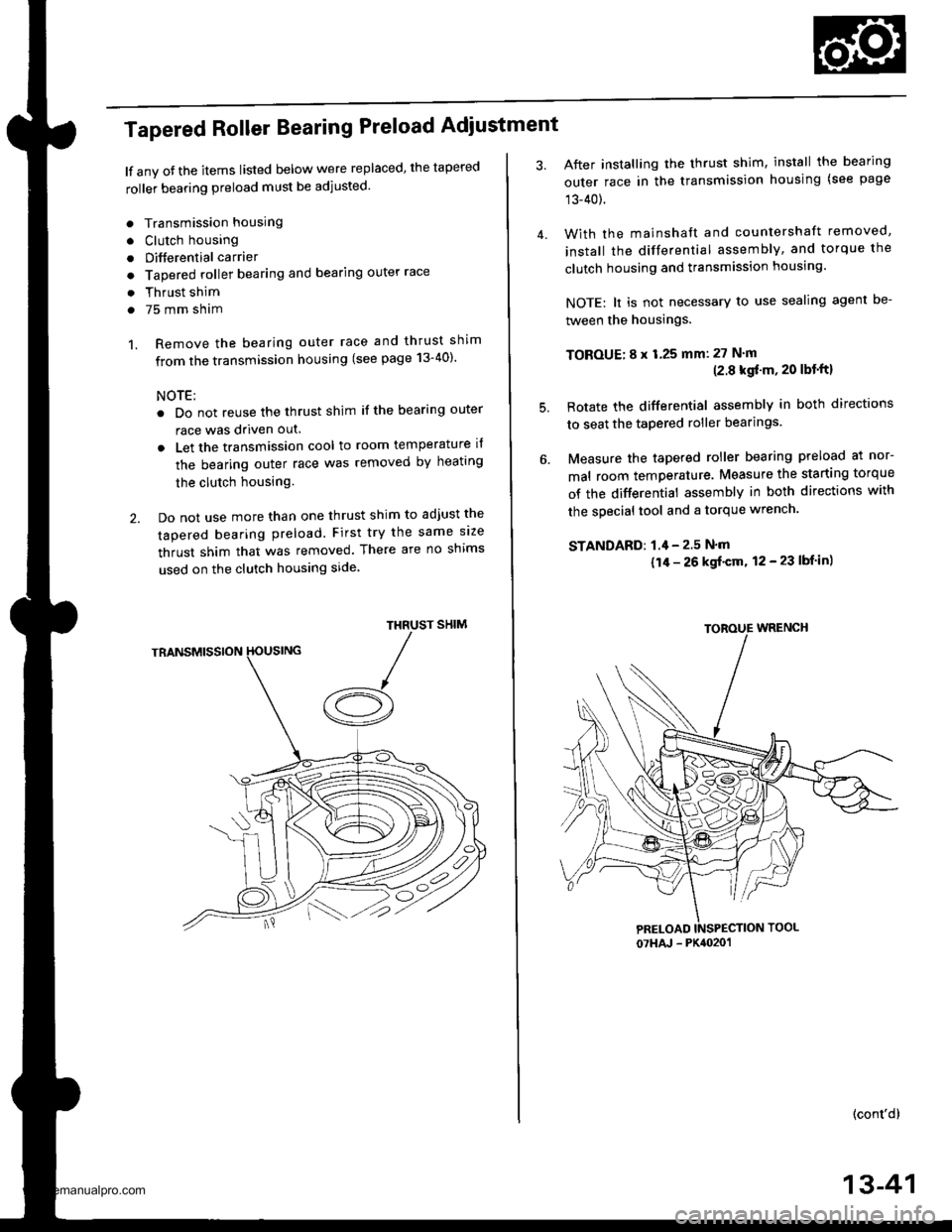
Tapered Roller Bearing Preload Adiustment
lf any oJ the items listed below were replaced, the tapered
roller bearing preload must be adjusted.
. Transmission housing
. Clutch housing
. Differential carrier
o Tapered roller bearing and bearing outer race
. Thrust shim
. 75 mm sham
1. Remove the bearing outer race and thrust shim
from the transmission housing (see page 13-40)'
NOTE:
. Do not reuse the thrust shim if the bearing outer
race was driven out.
. Let the transmission cool to room temperature il
the bearing outer race was removed by heating
the clutch housing.
2. Do not use more than one thrust shim to adjust the
tapered bearing preload. First try the same size
thrust shim that was removed. There are no shims
used on the clutch housing side
SHIMTHRUST
/A
After installing the thrust shim, install the bearing
outer race in the transmission housing (see page
13-40).
With the mainshaft and countershaft removed,
install the differential assembly, and torque the
clutch housing and transmission housing.
NOTE: lt is not necessary to use sealing agent be-
tween the housings.
TOBOUE; 8 x 1.25 mm: 27 N'm(2.8 kgf'm, 20 lbt'ftl
Rotate the differential assembly in both directions
to seat the tapered roller bearings.
Measure the tapered roller bearing preload at nor-
mal room temperature. Measure the starting torque
of the differential assembly in both directions with
the special tool and a torque wrench.
STANDAFD: 1.4 - 2.5 N'm
{1/r - 26 kgf'cm, 12 - 23 lbf in)
(cont'd)
4.
5.
07HAJ - PK4020'�1
13-41
www.emanualpro.com
Page 506 of 1395
Transmission Assembly
Reassembly
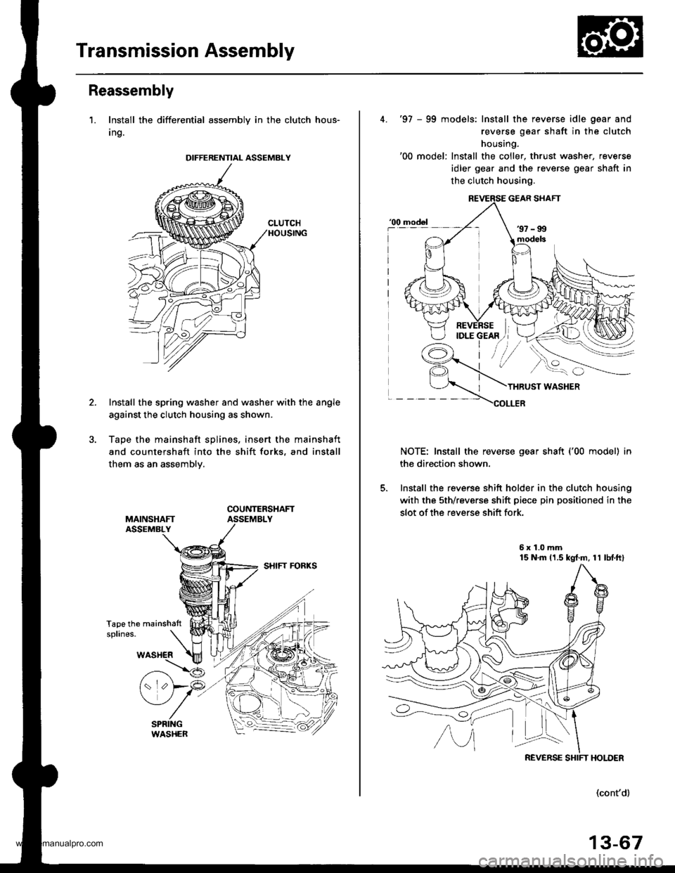
1. Install the differential assembly in the clutch hous-
Ing.
Install the spring washer and washer with the angle
against the clutch housing as shown.
Tape the mainshaft splines. insert the mainshaft
and countershaft into the shift forks, and install
them as an assemblv.
Tape the mainshattsplines.
DIFFERENTIAL ASSEMBLY
4. '97 - 99 models: Install the reverse idle gaar and
reverse gear shaft in the clutch
housing.'00 model: Install the coller, thrust washer, reverse
idler gear and the reverse gear shaft in
the clutch housing.
THRUST WASHER
COLLER
NOTE: Install the reverse gear shaft ('00 model) in
the direction shown.
5. Install the reverse shift holder in the clutch housing
with the sth/reverse shift piece pin positioned in the
slot of the reverse shift fork.
5x1.0mm15 N'm 11.5 kgt.m, 11 lbf.ftl
model
REVERSE SHIFT HOLDER
(cont'd)
13-67
www.emanualpro.com
Page 508 of 1395
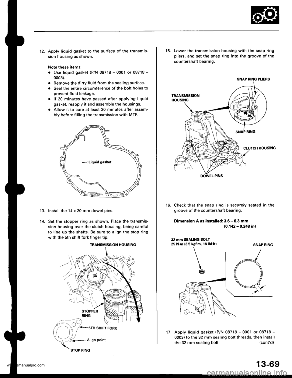
12. Apply liquid gasket to the surface of the transmis-
sion housing as shown.
Note these items:
. Use liquid gasket (P/N 08718 - 0001 or 08718 -
0003).
. Remove the dirty fluid from the sealing surface.
. Seal the entire circumterence of the bolt holes to
prevent fluid leakage.
. lf 20 minutes have passed after applying liquid
gasket, reapply it and assemble the housings.
a Allow it to cure at least 20 minutes after assem-
bly betore filling the transmission with MTF.
Install the 14 x 20 mm dowel pins.
Set the stopper ring as shown. Place the transmis-
sion housing over the clutch housing, being careful
to line up the shafts. Be sure to align the stop ring
with the 5th shift fork finger tip.
r3.
14.
TRANSMISSION HOUSING
SHIFT FORK
vk..*,
Align point
17.
the 32 mm sealing bolt.
15. Lower the transmission housing with the snap ring
pliers. and set the snap ring into the groove of the
countershaft bearing.
Check that the snap ring is securely seated in the
groove of the countershaft bearing.
Dimension A as installod: 3.6 - 6.3 mm
(0.142 - 0.2/8 in)
16.
32 mm SEALING BOLT25 N m 12.5 kgf.m, 18 lbf.ftlSNAP RING
(cont'd)
13-69
Apply liquid gasket (P/N 08718 - 0001 or 08718 -
0003) to the 32 mm sealing bolt threads, then install
SNAP RING PLIERS
DOWEL PINS
www.emanualpro.com