cts HONDA CR-V 1999 RD1-RD3 / 1.G User Guide
[x] Cancel search | Manufacturer: HONDA, Model Year: 1999, Model line: CR-V, Model: HONDA CR-V 1999 RD1-RD3 / 1.GPages: 1395, PDF Size: 35.62 MB
Page 276 of 1395
Troubleshooting
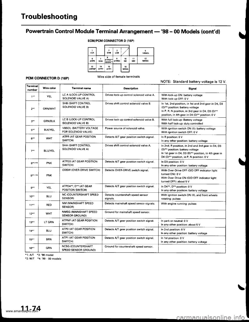
Powertrain Control Module Terminal Arrangement -'98 - 00 Models (cont'dl
PCM CONNECTOR D (16P)NOTE: Standard battery voltage is 12 V.
i1:A/T *3:'98 model'2: M/T *4:'99 00 models
ECM/PCM CONNECTOR D {16P}
Wire side of lemaleterminals
D€s4riptionSign!l
YELLC A {LOCK,UP CONTBOLSOLENOID VALVE A)Oriv€s lock'up conrrol solenoid valve A.With lock-up ON: b6ttery voltagsWith lock-up OFF:0 V
2+1GBN,M/HT
SHB (SHIFT CONTROLSOLENOIO VALVE B)Drives shift controlsolenoid valve B.In 1st, 2nd position, in lst and 2nd gear an D4, D3(D)11 position: battery vohag€In P, R, N position, in 3rd geaf in D1, D3 (D)*.position, in 4th gear in D4 (D)*r positionr0 V
GRN/BLKLC 8 (LOCK,UP CONTROLSOLENOID VALVE B}Drives lock up controlsolenoid valve B.With full lock-up: 8attery voitageWith half lock'uprduty controlled
BLK/YELVBSOL (BATTERY VOLTAGEFOR SOLENOID VALVE}Pow€r source of solenoid valvs.With ignition switch ON (ll): batteryvoltageWith ignition switch OFF| 0 V
ATPR {AI GEAE POSITIONSWITCH)Delscls A/T gear posrtion swirch srgnal.In any other positjon: battsry voltage
BLU,ryEL
SHA (SHIFT CONTROLSOLENOID VALVE A)Drives shift conrrol solenoid valvp A.In 2nd, R position, an 2nd and 3rd ge6r in D4, D3(D)r' posilion: batlery voltageIn 1st gear in 04, 03 {D)}. position, in 4th gear inD4 (D)*. position, in P, N position:0 V
PNKATPD3 (AT GEAR POSITIONswrTcH)Detects A,/T g€ar poshion swirch sign6l.In D3 position:0 Vh any other posiiion: ban€ryvoltage
PNK
ODSW (OVER.DBIVE SWITCH)Detects OVEF-DRIVE swirch sagnal.With Ovor Drivs OFF (O/D OFF indicator lightturned ON): 0 VWilh Ovsr Drivs ON (O/D OFF indicrto.lashtturned OFF): about 5 V
9''YELATPDI}3, O}I {AT GEARPOStTtON SWTTCH)Dot€cts A/T g€ar position swirch signal.In D4r3, O*. position:0 VIn any other posilion: battery voltage
10.,BLUNC (COUNIERSHAFT SPEEDSENSOR)Detscts counl€rshaft speed sensorWith ignition switch ON (ll), and ffonr wheels
REDNM IIVAINSHAFT SPEEDSENSOB)Detects mainshaft speed sensor sign6ls.Wilh engine running: pulses
NMSG {MAINSHAFTSPEEDSENSOB GBOUND)Ground for mainshaft speed sensor-
'13*1LT GRNATPNP (AT GEAR POSITIONswtTcH)Delects A,/T gear position switch signat.In park or n€utral:0 Vh any other posilion: about 5 V
8LUATP2 (AT GEAR POSFIONswrTcH)Dstects A,/T gear position switch signal.h any othsr position: battery voltsgs
15.'BRNATP1 {AT GEAR POSITIONswrTcH)Detscts A/T gear position switch signal.In any other position: htteryvoltage
t6''GRNNCSG {COUNTERSHAFTSPEED SENSOR GROUND}Grouod for counterchaft sp€ed s€nsor.
11-74
www.emanualpro.com
Page 281 of 1395
How to Read Flowcharts
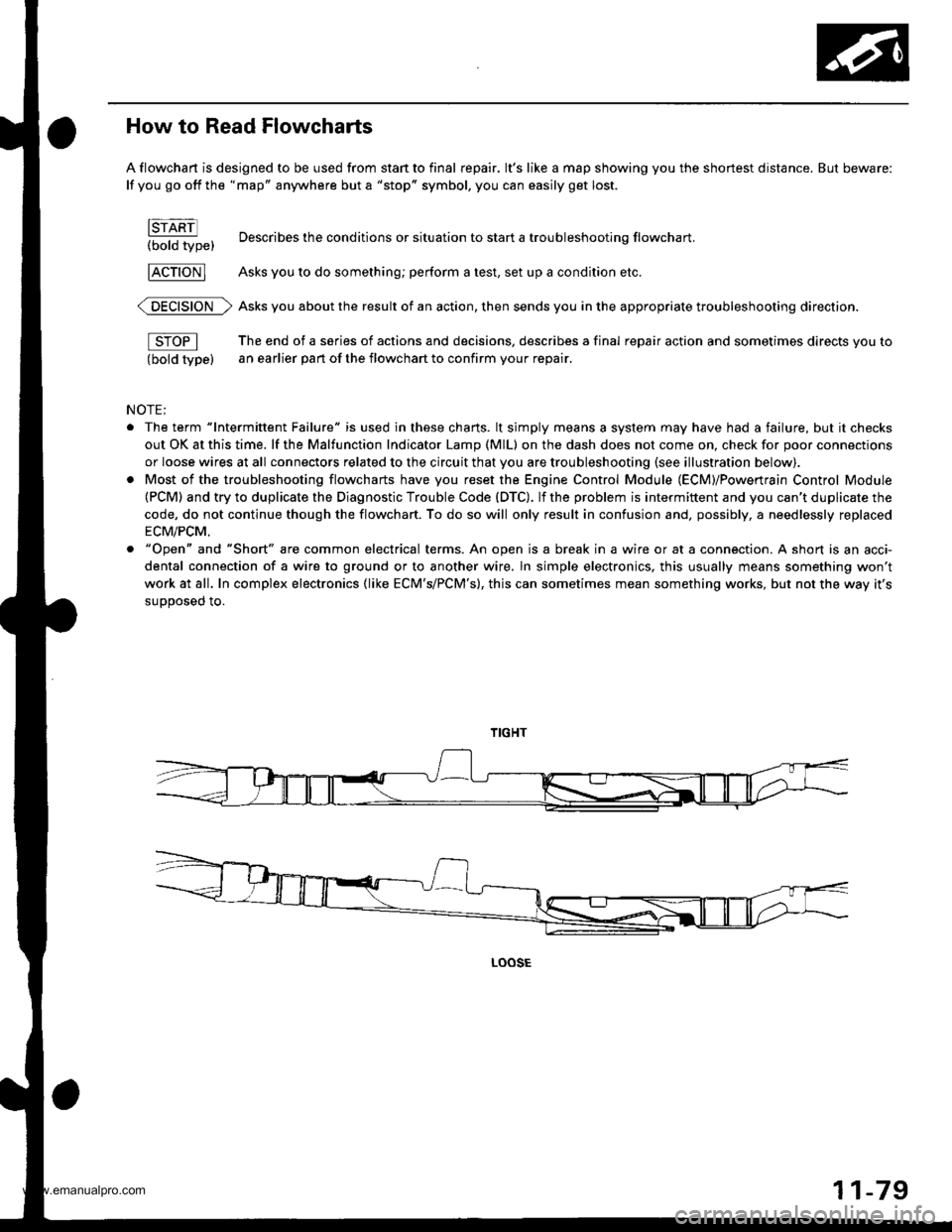
A flowchart is designed to be used from start to final repair. lt's like a map showing you the shortest distance. But beware:
lf you go off the "map" anywhere but a "stop" symbol, you can easily get lost.
brARn
t.-OotO tw"t Describes the conditions or situation to start a troubleshooting flowchart.
FcTloNl Asks you to do something; perform a test, set up a condition etc.
@ Asks you about the result of an action, then sends you in the appropriate troubleshooting direction.
fS-OPl The end of a series of actions and decisions, describes a final repair action and sometimes directs you to
(bold type) an earlier part of the flowchart to confirm your repair.
NOTE:
. The term "lntermittent Failure" is used in these charts. lt simply means a system may have had a failure, but it checks
out OK at this time. lf the Malfunction Indicator Lamp (MlL) on the dash does not come on, check for poor connections
or loose wires at all connectors related to the circuit that you are troubleshooting (see illustration below).
. Most of the troubleshooting flowcharts have you reset the Engine Control Module (EcM)/Powertrain Control Module(PCM) and try to duplicate the Diagnostic Trouble Code (DTC). lf the problem is intermittent and you can't duplicate the
code, do not continue though the flowchart. To do so will only result in confusion and, possibly, a needlessly replaced
ECM/PCM,
o "Open" and "Short" are common electrical terms. An open is a break in a wire or at a connection. A short is an acci-
dental connection of a wire to ground or to another wire. ln simple electronics, this usually means something won't
work at all. In complex electronics (like ECM'S/PCM'S), this can sometimes mean something works, but not the way it's
suooosed to.
LOOSE
11-79
www.emanualpro.com
Page 333 of 1395
tro-rsl
1Tffi61
tF136t
fPfa6r-1
tF138tl
I-Pi382l
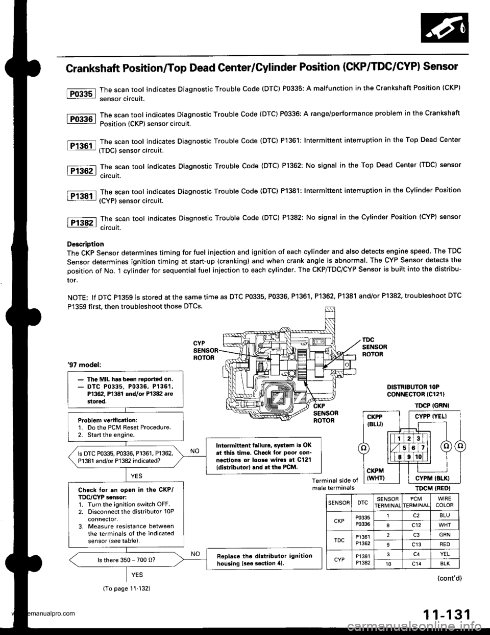
Crankshaft Position/Top Dead Genter/Gylinder Position (CKP/TDC/CYPI Sensor
The scan tool indicates Diagnostic Trouble Code (DTC) P0335; A malfunction in the Crankshaft Position (CKP)
sensor circuit,
The scan tool indicates Diagnostic Trouble Code (DTC) P0336: A range/performance problem in the Crankshaft
Position {CKP) sensor circuit.
The scan tool indicates Diagnostic Trouble Code {DTC) P1361: Intermittent interruption in the Top Dead Center
(TDC) sensor circuit.
The scan tool indicates Diagnostic Trouble Code (DTC) P1362: No signal in the Top Dead Center (TDC) sensor
ci.cuit.
The scan tool indicates Diagnostic Trouble Code (DTC) P1381: Intermittent interruption in the Cylinder Position
(CYP) sensor circuit.
The scan toot indicates Diagnostic Trouble Code {DTC) P1382: No signal in the Cylinder Position (CYP} sensor
circuit.
Description
The CKP Sensor determines timing for fuel injection and ignition of each cylinder and also detects engine speed. The TDC
Sensor determines ignition timing at start-up {cranking) and when crank angle is abnormal. The CYP Sensor detects the
position of No. 't cylinder for sequential fuel injection to each cylinder. The CKP/TDC/CYP Sensor is built into the distribu-
ror.
NOTE: lf DTC P1359 is stored atthesametimeas DTC P0335, P0336, Pl361, P1362, P1381 and/or P1382, troubleshoot DTC
P1359 first, then troubleshoot those DTCS.
DISTRIBUTOR lOPCoNNECTOR (Cl211
TDCP IGRNI
Terminal side ofmale terminalsTIrcM IREOI
'97 model:
- The MIL has be€n reported on.- DTC P0335, P0336, P136'�1,P1362, Pl341 and/oi P1382 arestored.
Problem verific.tion:1. Do the PCM Reset Procedure.2. Start the engine.
Intermittent lailure, 3yd6m i3 OKat thb tims. Chcck tor poor con-nections ol looso wire3 si C12'l
ldistributor) .nd .t the PCM.
ls DTC P0335, P0336, P1361, P1362,P1381 and/or P1382 indicated?
Ch.ck for an open in tho CKP/TDC/CYP sensor:1. Turn the ignition switch OFF.2. Disconnect the distributor 10Pconnector.3. Measure resistance betweenthe terminals of the indicatedsensor (see table).
Replace tho distributor ignitionhousing {sea 3ection 41.ls there 350 - 700 o?
(To page 11-132)
CYPP IYELI
CYPM (BLKI
SENSOEDTCSENSOBPCMERMINAIWIRECOLOR
CKPP0335P0336
lc28LU
8c12
TDCP1361P1352
2GRN
9c13RED
CYPP'�I381P1342
3c4YEL't0c14BLK
{cont'd)
11-131
www.emanualpro.com
Page 370 of 1395
ldle Control System
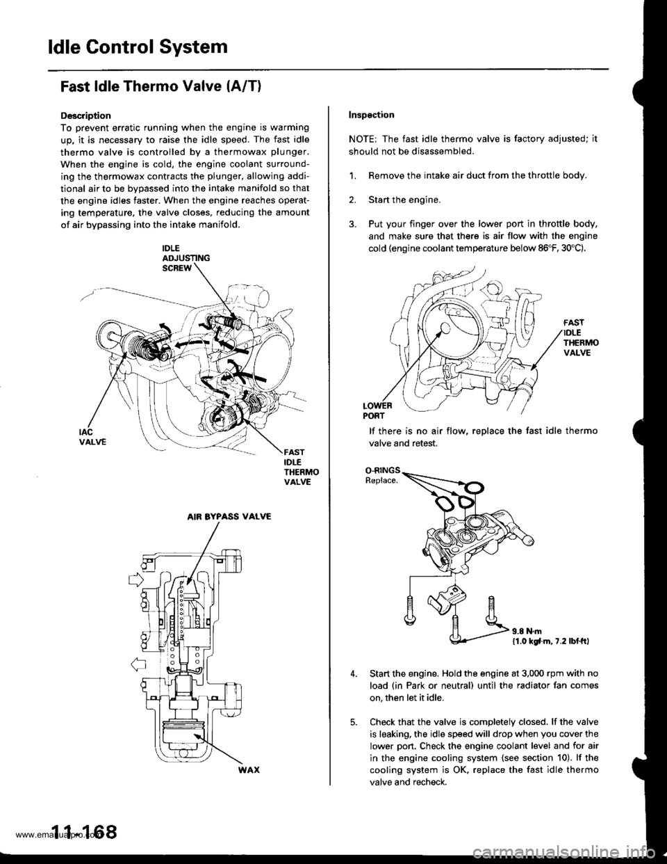
Fast ldle Thermo Valve lA/T)
Description
To prevent erratic running when the engine is warming
up, it is necessary to raise the idle speed. The fast idle
thermo valve is controlled by a thermowax plunger.
When the engine is cold, the engine coolant surround-
ing the thermowax contracts the plunger, allowing addi-
tional air to be bvDassed into the intake manifold so that
the engine idles faster. When the engine reaches operat-
ing temperature. the valve closes, reducing the amount
of air bypassing into the intake manifold.
IDLEADJUSTING
IDLETHERMOVALVE
AIR BYPASS VALVE
11-168
Inspgction
NOTE: The fast idle thermo valve is factory adjusted; it
should not be disassembled.
1. Remove the intake air duct from the throttle body.
2. Start the engine,
3. Put your finger over the lower port in throttle body,
and make sure that there is air flow with the engine
cold (engine coolant temperature below 86"F, 30'C).
lf there is no air flow, replace the fast idle thermo
valve and retest,
O-RINGSReplace.
11.0 kgfl.m, 7.2 lbl.ftl
Start the engine. Hold the engine at 3,000 rpm with no
load (in Park or neutral) until the radiator fan comes
on, then let it idle.
Check that the valve is completely closed. lf the valve
is leaking, the idle speed will drop when you cover the
lower pon. Check the engine coolant level and for air
in the engine cooling system {see section 10). lf the
cooling system is OK, replace the fast idle thermo
valve and recheck.
www.emanualpro.com
Page 377 of 1395
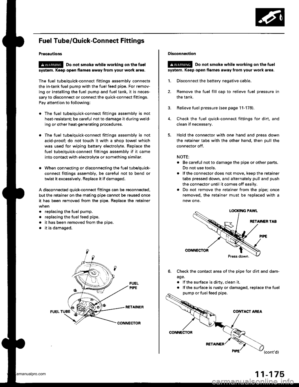
Fuel Tube/Ouick-Gonnect Fittings
Procautions
@ Do not smoke whils working on the fuel
syst6m, Koop open flames away from your work ar9a.
The fuel tube/quick-connect fittings assembly connects
the in-tank fuel pump with the fuel feed pipe. For remov-
ing or installing the fuel pump and fuel tank, it is neces-
sary to disconnect or connect the quick-connect fittings.
Pay attention to following;
. The fuel tube/quick-connect fittings assembly is not
heat-resistant; be careful not to damage it during weld-
ing or other heat-generating procedures.
. The fuel tube/quick-connect fittings assembly is not
acid-proof; do not touch it with a shop towel which
was used for wiping battery electrolyte. R€place the
fuel tube/quick-connect fittings assembly if it came
into contact with electrolyte or somethino similar.
. When connecting or disconnecting the fuel tube/quick-
connect fittings assembly, be careful not to bend or
twist it excessively, Replace it if damaged,
A disconnected quick-connect fittings can be reconnected,
but the retainer on the mating pipe cannot be reused once
it has been removed from the pipe. Replace tha retainer
. replacing the fuel pump.
. replacing the fuelfeed pipe,
. it has been removed from the Dioe,
. it is damaged.
RCTAINERFUEL TUBE
CONNECTOR
CONNECTOR
RETAINER
11-175
Disconnection
!@ Do not smoke while working on the fuel
syst6m. Keep open flames away from your work area.
1. Disconnect the battery negative cable.
2. Remove the fuel fill cap to relieve fuel pressure in
the tank.
3. Relieve fuel pressure (see page 11-178).
4. Check the fuel quick-connect fittings for dirt, and
clean if necessary.
5. Hold the connector with one hand and press down
the retainer tabs with the other hand. then pull the
connector off.
NOTE:
. Be careful not to damage the pipe or other parts.
Do not use tools,
. lf the connector does not move, keep the retainer
tabs pressed down, and alternately pull and push
the connector until it comes off easily.
. Do not remove the retainer from the pipe; once
removed, the retainer must be replaced with a
new one.
LOCKII{G PAWL
RETANEN TAB
@NNCCTOR
Press down.
6. Check the contact area of the pipe for dirt and dam-
age.
. lf the surface is dirW, clean it
. lf the surface is rusty or damaged, replace the fuel
pump or fuel feed pipe,
CONTACT ANEA
{cont'd}
www.emanualpro.com
Page 431 of 1395
Clutch Pedal
Adiustment
NOTE:
. To check the clutch interlock switch and clutch
switch, see section 23.
. The clutch is self-adjusting to compensate for wear.
CAUTION: lf there is no clearance bstwa€n the mas-
ter cylinder piston and push rod, ths roloase bearingis held againsi the diaphragm spring, which canresuh in clutch slippage or other clutch probloms.
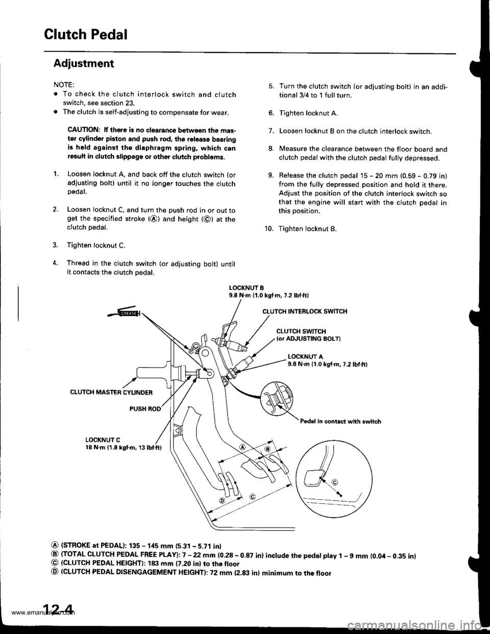
1. Loosen locknut A, and back off the clutch switch (or
sdjusting bolt) until it no longer touches the clutchpeoar.
2. Loosen locknut C, and turn the push rod in or out toget the specified stroke (@) and height (@) at theclutch oedal.
3. Tighten locknut C.
4. Thread in the clutch swirch (or adjusting bolt) untilit contacts the clutch oedal.
7.
5.
8.
q
Turn the clutch switch {or adjusting bolt} in an addi-
tional 3/4 to 1 full turn.
Tighten locknut A.
Loosen locknut B on the clutch interlock switch.
Measure the clearance between the floor board and
clutch pedalwith the clutch pedal fully depressed.
Release the clutch pedal 15 - 20 mm (0.59 - 0.79 in)
from the fully depressed position and hold it there,Adjust the position of the clutch interlock switch sothat the engine will start with the clutch pedal in
this position.
Tighten locknut B.10.
LOCKNUT B9.8 N.m 11.0 kgf.m, 7.2 lbf.ftl
CLUTCH INTERLOCK SWITCH
CLUTCH SWTTCH{or ADJUSTING BOLTI
L(rcKNUT A9.8 N.m {1.0 kg{.m,7.2 lbf.ftl
CLUTCH MASTER CYLINDER
PUSH ROD
Pedal in contact with swhch
LOCKNUT C18 N.m (1.8 kgf.m, 13lbtftl
@ {STROKE at PEDAL): 135 - 1its mm (5.31 - 5.71 in}
@ (TOTAL CLUTCH PEDAL FREE PLAY)i7 -22mm (0.28-0.87 in) inctude the pedat ptay 1 - 9 mm (0.0it- 0.35 inl@ (GLUTC,H PEDAL HE|GHTI: ltxt mm (7.20 inl ro rhe ftoor
o (CLUTCH PEDAL DTSENGAGEMENT HEtcHTl: 72 mm {2.txt inl minimum to the floor
\,/a_-_--/
12-4
www.emanualpro.com
Page 445 of 1395
Transfer Assembly
lnstallation
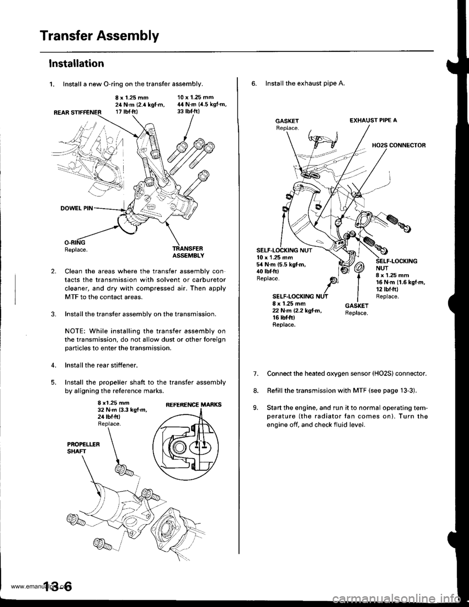
1. Install a new O-ring on the transfer assembly.
8 x 1.25 mm24 N.m (2.4 kgt m,17 rbt.ftl
10 x 1.25 mm44 N.m (4.5 kgJ.m,
2.
DOWEL PIN
Replace.TRANSFEBASSEMBLY
Clean the areas where the transfer assembly con
tacts the transmission with solvent or carburetor
cleaner, and dry with compressed air. Then apply
MTF to the contact areas.
Installthe transfer assembly on the transmission.
NOTE: While installing the transfer assembly on
the transmission, do not allow dust or other foreign
particles to enter the transmission.
lnstall the rear stiffener.
Install the propeller shaft to the transfer assembly
by aligning the reference marks,
8 x1.25 mm32 N.m 13.3 kg{.m,24 tbf.ftl
REFERENCE MARKS
6. Install the exhaust pipe A,
GASKETEXHAUST PIPE A
HO2S CONNECTOR
10 x 1 .25 mm54 N.m (5.5 kgt m,40 tbtfttReplace.
SELF.LOCKING
NUT8 x 1.25 mm16 N.m {1.6 kgf.m,12 tbt.ft)Replace.8 x 1.25 mmzzN.m l2.2kg!-m,16 rbf.trtReplace.
7.Connect the heated oxygen sensor (HO2S) connector.
Relill the transmission with MTF (see page 13-3).
Start the engine, and run it to normal operating tem-
perature (the radiator tan comes on). Turn the
engine off. and check fluid level.
8.
9.
www.emanualpro.com
Page 505 of 1395
Mainshaft Thrust Clearance
Adjustment (cont'dl
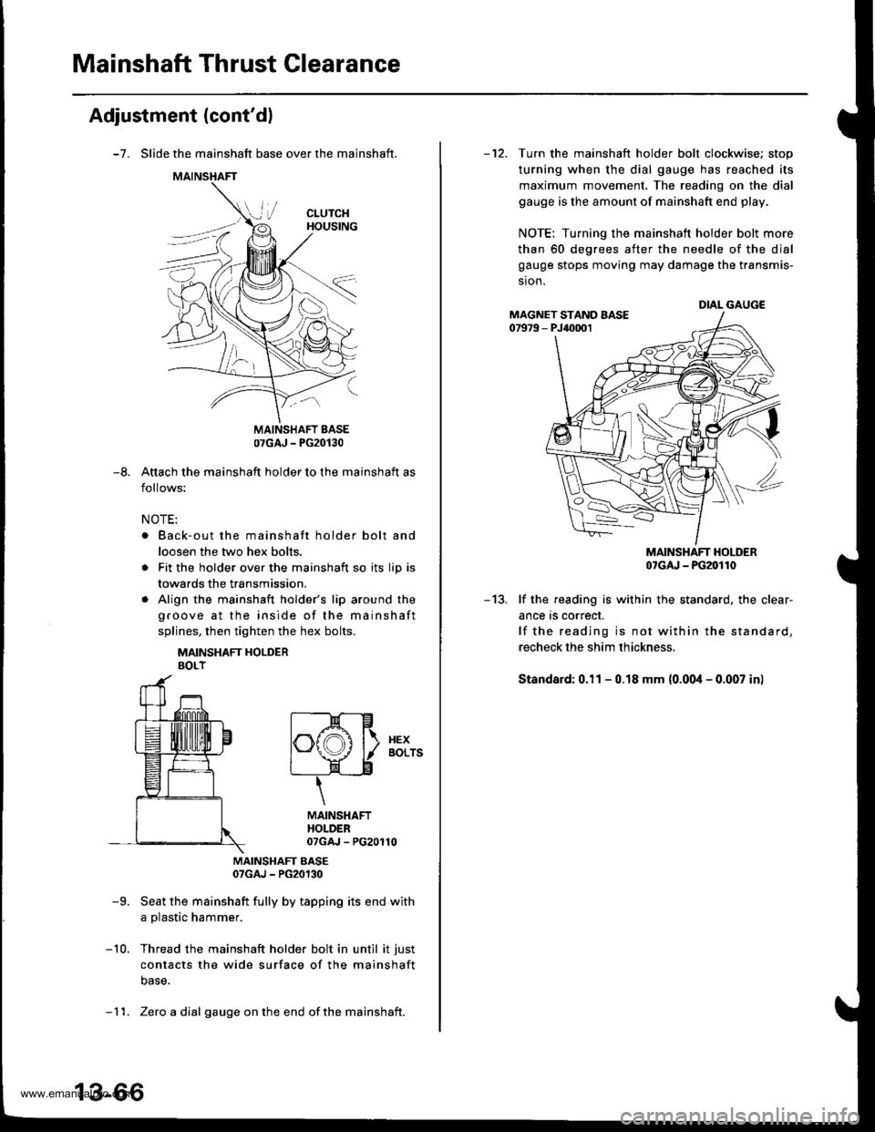
-7. Slide the mainshaft base over the mainshaft.
Attach the mainshaft holder to the mainshaft as
follows:
NOTE:
. Back-out the mainshaft holder bolt and
loosen the two hex bolts.
. Fit the holder over the mainshaft so its lip is
towards the transmission.
. Align the mainshaft holder's lip around the
groove at the inside of the mainshaft
splines, then tighten the hex bolts.
MAINSHAFT HOLDERBOLT
MAINSHAFT EASE07GAJ - PG20130
-9. Seat the mainshaft fully by tapping its end with
a plastic hammer.
-10. Thread the mainshaft holder bolt in until it just
contacts the wide surface of the mainshaft
base.
07GAJ - PG20130
-8.
t--E-Hlf\f,A l\. xex
l"\y I aors
t____=__)"n-____"8
\
MAINSHAFTHOLDER07GAJ - PG20110
- 11. Zero a dial gauge onthe end ofthe mainshait.
-12. Turn the mainshaft holder bolt clockwise; stop
turning when the dial gauge has reached its
maximum movement, The reading on the dial
gauge is the amount of mainshaft end play.
NOTE: Turning the mainshaft holder bolt more
than 60 degrees after the needle of the dial
gauge stops moving may damage the transmis-
sion.
MAINSHAFT HOLDER07cru - PG20110
-13. lf the reading is within the standard, the clear-
ance rs correct.
lf the reading is not within the standard,
recheck the shim thickness.
Standard: 0.11 - 0.18 mm (0.00i1- 0.007 inl
DIAL GAUGEMAGNET STAND AASE07979 - PJ40001
www.emanualpro.com
Page 543 of 1395
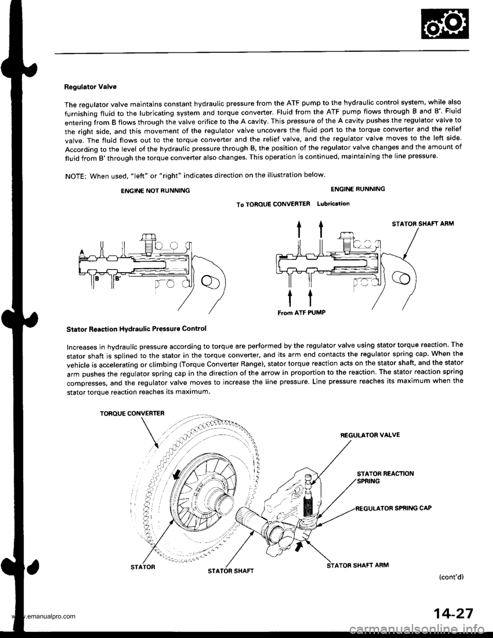
Regulator Valve
The regulator valve maintains constant hydraulic pressure from the ATF pump to the hydraullc control system, while also
furnishing fluid to the lubricating system and torque converter. Fluid from the ATF pump flows through B and B'. Fluid
entering from B flows through the valve orifice to the A cavity. This pressure of the A cavity pushes the regulator valve to
the right side. and this movement of the regulator valve uncovers the fluid port to the torque converter and the relief
valve. The fluid flows out to the torque converter and the relief valve, and the regulator valve moves to the left side.
According to the level of the hydraulic pressure through B, the position of the regulator valve changes and the amount of
fluid from B,through the torque converter also changes. This operation is continued, maintaining the line pressure.
NOTE; When used, "|eft" or "right" indicates direction on the illustration below.
ENGINE NOT RUNNING
STATOR SHAFT ABM
Stator Reaction Hydraulic Pressurs Control
Increases in hydraulic pressure according to torque are performed by the regulator valve using stator torque reaction. The
stator shaft is splined to the stator in the torque converter, and its arm end contacts the regulator spring cap When the
vehicle is accelerating or climbing (Torque Converter Range), stator torque reaction acts on the stator shaft, and the stator
arm pushes the regulator spring cap in the direction of the arrow in proportion to the reaction. The stator reaction spring
compresses, and the regulator valve moves to increase the line pressure. Line pressure reaches its maximum when the
stator torque reaction reaches its maximum.
TOROUE CONVERTER
REGULATON VALVE
STATOR REACTION
TOR SPRING CAP
(cont'd)
ENGINE RUNNING
To TOROUE CONVERTER Lubtication
STATONSTASHAFTATOF SHAFT ARM
14-27
www.emanualpro.com
Page 633 of 1395
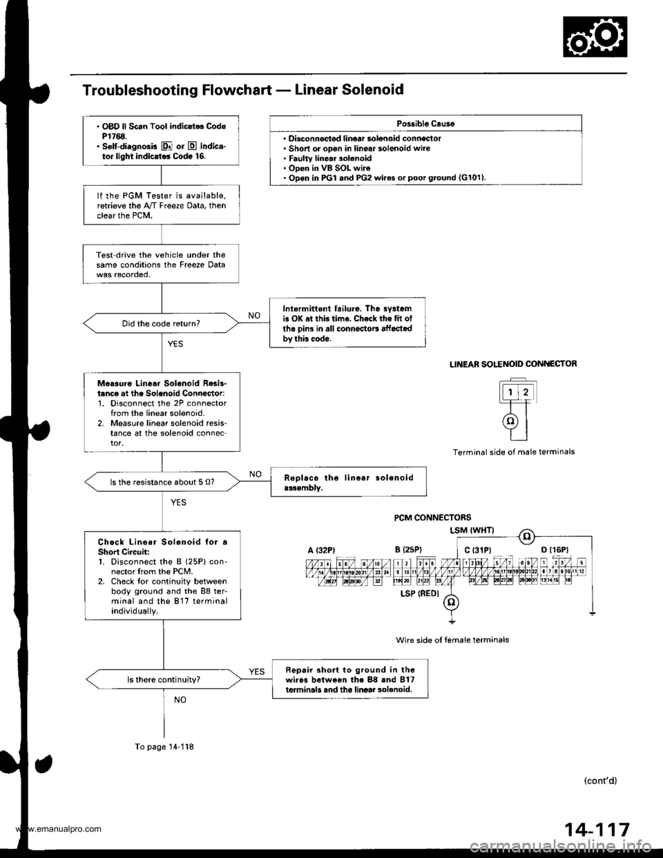
Po$ible Cau3e
' Disconnectsd linoar solenoid conneclol. Short or open in linear solenoid wire. Faulty linear 3olenoid. Open in VB SOL wire. Open in PGI and PG2 wires or poot g.ound {G101).
. OBD ll Scan Tool indic{t.. CodsP1768.. selt-diagnosis El or E indica-tor light indicrt.. Codo 16.
lf the PGM Tester is available.retrieve the A/T Freeze Data, thenclear the PCM.
Test drive the vehicle under thesame conditions the Freeze Data
Inlermittont tailure, The 3yrtomis OK at thb time. Check the tit otlhe oins in all connectoE affoctodby this code.
Did the code return?
Meaaure Linear Solenoid R€sis-tanc€ at the Solenoid Connector:1. Disconnect the 2P connectorfrom the linear solenoid-2. Measure linear solenoid resis-tance at the solenoid connector.
ls the resistance about 5 O?
Chock Lino.r Sol.noid to. aShort Circuh:1. Disconnect the B (25P) con-nector lrom the PCM.2. Check tor continuity betweenbody ground and the 88 ter-minal and the 817 terminalindividually.
Repair 3ho to ground in thewires belween the 88 rnd B17terminals and tho linaar 3olenoid.ls there continuity?
A l32PtB {2sP)
LSP (REDI
To page 14-118
SOLENOID COiINECTOR
t-rtt
(9l
tt
LINEAR
Terminal side ol male terminals
wire side oI temale terminals
(cont'd)
14-117
www.emanualpro.com