power wire HONDA CR-V 1999 RD1-RD3 / 1.G User Guide
[x] Cancel search | Manufacturer: HONDA, Model Year: 1999, Model line: CR-V, Model: HONDA CR-V 1999 RD1-RD3 / 1.GPages: 1395, PDF Size: 35.62 MB
Page 276 of 1395
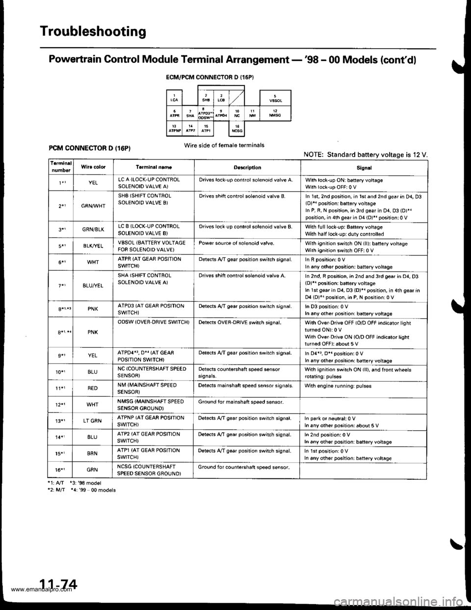
Troubleshooting
Powertrain Control Module Terminal Arrangement -'98 - 00 Models (cont'dl
PCM CONNECTOR D (16P)NOTE: Standard battery voltage is 12 V.
i1:A/T *3:'98 model'2: M/T *4:'99 00 models
ECM/PCM CONNECTOR D {16P}
Wire side of lemaleterminals
D€s4riptionSign!l
YELLC A {LOCK,UP CONTBOLSOLENOID VALVE A)Oriv€s lock'up conrrol solenoid valve A.With lock-up ON: b6ttery voltagsWith lock-up OFF:0 V
2+1GBN,M/HT
SHB (SHIFT CONTROLSOLENOIO VALVE B)Drives shift controlsolenoid valve B.In 1st, 2nd position, in lst and 2nd gear an D4, D3(D)11 position: battery vohag€In P, R, N position, in 3rd geaf in D1, D3 (D)*.position, in 4th gear in D4 (D)*r positionr0 V
GRN/BLKLC 8 (LOCK,UP CONTROLSOLENOID VALVE B}Drives lock up controlsolenoid valve B.With full lock-up: 8attery voitageWith half lock'uprduty controlled
BLK/YELVBSOL (BATTERY VOLTAGEFOR SOLENOID VALVE}Pow€r source of solenoid valvs.With ignition switch ON (ll): batteryvoltageWith ignition switch OFF| 0 V
ATPR {AI GEAE POSITIONSWITCH)Delscls A/T gear posrtion swirch srgnal.In any other positjon: battsry voltage
BLU,ryEL
SHA (SHIFT CONTROLSOLENOID VALVE A)Drives shift conrrol solenoid valvp A.In 2nd, R position, an 2nd and 3rd ge6r in D4, D3(D)r' posilion: batlery voltageIn 1st gear in 04, 03 {D)}. position, in 4th gear inD4 (D)*. position, in P, N position:0 V
PNKATPD3 (AT GEAR POSITIONswrTcH)Detects A,/T g€ar poshion swirch sign6l.In D3 position:0 Vh any other posiiion: ban€ryvoltage
PNK
ODSW (OVER.DBIVE SWITCH)Detects OVEF-DRIVE swirch sagnal.With Ovor Drivs OFF (O/D OFF indicator lightturned ON): 0 VWilh Ovsr Drivs ON (O/D OFF indicrto.lashtturned OFF): about 5 V
9''YELATPDI}3, O}I {AT GEARPOStTtON SWTTCH)Dot€cts A/T g€ar position swirch signal.In D4r3, O*. position:0 VIn any other posilion: battery voltage
10.,BLUNC (COUNIERSHAFT SPEEDSENSOR)Detscts counl€rshaft speed sensorWith ignition switch ON (ll), and ffonr wheels
REDNM IIVAINSHAFT SPEEDSENSOB)Detects mainshaft speed sensor sign6ls.Wilh engine running: pulses
NMSG {MAINSHAFTSPEEDSENSOB GBOUND)Ground for mainshaft speed sensor-
'13*1LT GRNATPNP (AT GEAR POSITIONswtTcH)Delects A,/T gear position switch signat.In park or n€utral:0 Vh any other posilion: about 5 V
8LUATP2 (AT GEAR POSFIONswrTcH)Dstects A,/T gear position switch signal.h any othsr position: battery voltsgs
15.'BRNATP1 {AT GEAR POSITIONswrTcH)Detscts A/T gear position switch signal.In any other position: htteryvoltage
t6''GRNNCSG {COUNTERSHAFTSPEED SENSOR GROUND}Grouod for counterchaft sp€ed s€nsor.
11-74
www.emanualpro.com
Page 281 of 1395
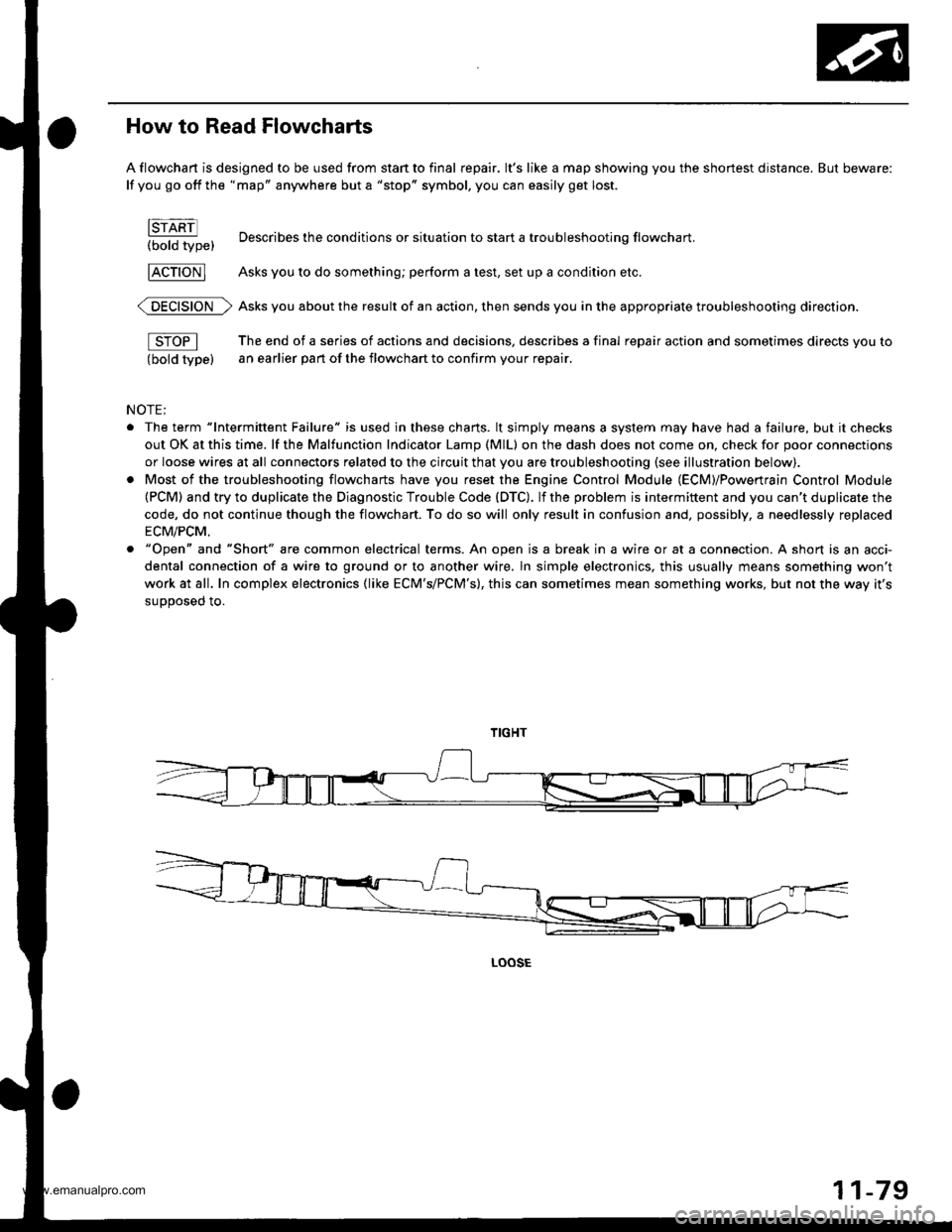
How to Read Flowcharts
A flowchart is designed to be used from start to final repair. lt's like a map showing you the shortest distance. But beware:
lf you go off the "map" anywhere but a "stop" symbol, you can easily get lost.
brARn
t.-OotO tw"t Describes the conditions or situation to start a troubleshooting flowchart.
FcTloNl Asks you to do something; perform a test, set up a condition etc.
@ Asks you about the result of an action, then sends you in the appropriate troubleshooting direction.
fS-OPl The end of a series of actions and decisions, describes a final repair action and sometimes directs you to
(bold type) an earlier part of the flowchart to confirm your repair.
NOTE:
. The term "lntermittent Failure" is used in these charts. lt simply means a system may have had a failure, but it checks
out OK at this time. lf the Malfunction Indicator Lamp (MlL) on the dash does not come on, check for poor connections
or loose wires at all connectors related to the circuit that you are troubleshooting (see illustration below).
. Most of the troubleshooting flowcharts have you reset the Engine Control Module (EcM)/Powertrain Control Module(PCM) and try to duplicate the Diagnostic Trouble Code (DTC). lf the problem is intermittent and you can't duplicate the
code, do not continue though the flowchart. To do so will only result in confusion and, possibly, a needlessly replaced
ECM/PCM,
o "Open" and "Short" are common electrical terms. An open is a break in a wire or at a connection. A short is an acci-
dental connection of a wire to ground or to another wire. ln simple electronics, this usually means something won't
work at all. In complex electronics (like ECM'S/PCM'S), this can sometimes mean something works, but not the way it's
suooosed to.
LOOSE
11-79
www.emanualpro.com
Page 284 of 1395
PGM-FI System
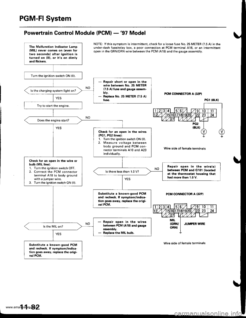
Powertrain Control Module {PCM} -'97 Model
NOTE: lf this symptom is intermiftent, check for a loose fuse No. 25 METER (7.5 A) in theunderdash f{rse/relay box, a poor connection at PCM terminal A18, or an intermittentopen in the GRN/ORN wire between the PCM (A18) and the gauge assembly.
PCM OON ECTOR A {32P}
Wire side of female terminals
PCM CONNECTOR A {32PI
Wire side ot temale terminals
11-42
The Malfunction lndicator LamD(MlL) nev6r comes on {even lortwo seconds) after ignition isturned on (lll, or it's on dimlyand flickers.
Turn the ignition switch ON {ll}.
- Rep.ir short or opon in thowire batween No. 25 METER(7.5 Alfuso and gauge a$€m-bty.- R6pl.c€ No. 25 METER 17.5 Alfus€.
ls the charging system light on?
Try to stan the engine.
Does the engine start?
Chock tor.n open in th6 wire3{PG1, PG2linesl:1. Turn the ignition switch ON (ll).2. Measure voltage betweenbody ground and PCM con-nector terminals A10 and A23individually.
Check for an op€n in the wir6 orbulb (MlL lin€l:1. Turn the ignition switch OFF.2. Connect the PCM connectorterminal A18 to body groundwith a iumper wire.3. Turn the ignition switch ON {ll).
n€peir open in tho wirelslhwoon PCM and Glol (loc!t.d
at thc tha.mo3tat houling thrthtd moro th.n 1.0 V.
ls thore l€ss than 1.0 V?
Substituto . known-good PCMand r€check. ll symptom/indica-tion goss away, rcplaca the origi-nal PCM.
- R6pai. open in th. wileibelwoon rcM lAl8l dnd g.ugea3rombly.- Roolac€ the MIL bulb.
ls the MIL on?
Substitut6 a known-good PCMand rocheck. ll 3ymptom/indica-tion goes away, replace the o.igi-n.l PCM.
PGl IBLKI
www.emanualpro.com
Page 286 of 1395
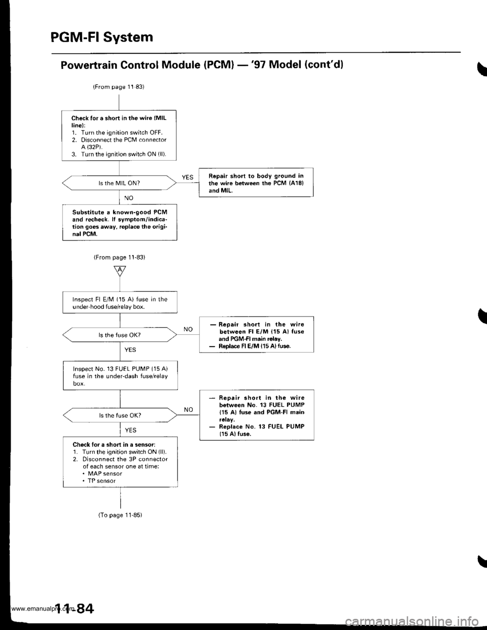
Powertrain Control Module (PCM) -'97 Model (cont'dl
(From page 11 83)
Check for a short in the wire (MlL
line):1. Turn the ignition switch OFF.2. Disconnect the PCM connectorA {32P).3. Turn the ignition switch ON (ll).
Repair short to body ground inthe wire between the PCM {418}and MlL.ls the MIL ON?
Substitute a known-good PCMand recheck. lf symptom/indica-tion goes away. replace the origi-nal PCM.
Inspect Fl E/M (15 A) fuse in theundeFhood fuse/relay box.
- Reoair shod in the wirebetween Fl E/M {15 A} fuseand PGM-FI main relav.- Replace FIE/M 115 A)fuse.
Inspect No. 13 FUEL PUMP (15 Aifuse in the underdash fuse/relay
- Repair short in lh€ wirebolween No. 13 FUEL PUMP
115 A) Iuse and PGM-FI main
- Replace No. 13 FUEL PUMP
115 A) fuse.
Check loJ a short in a sensor:1. Turn the ignit;on switch ON (ll).
2. Disconnect the 3P connectorof each sensor one at time:. MAP sensor
(To page 11-85)
11-84
www.emanualpro.com
Page 288 of 1395
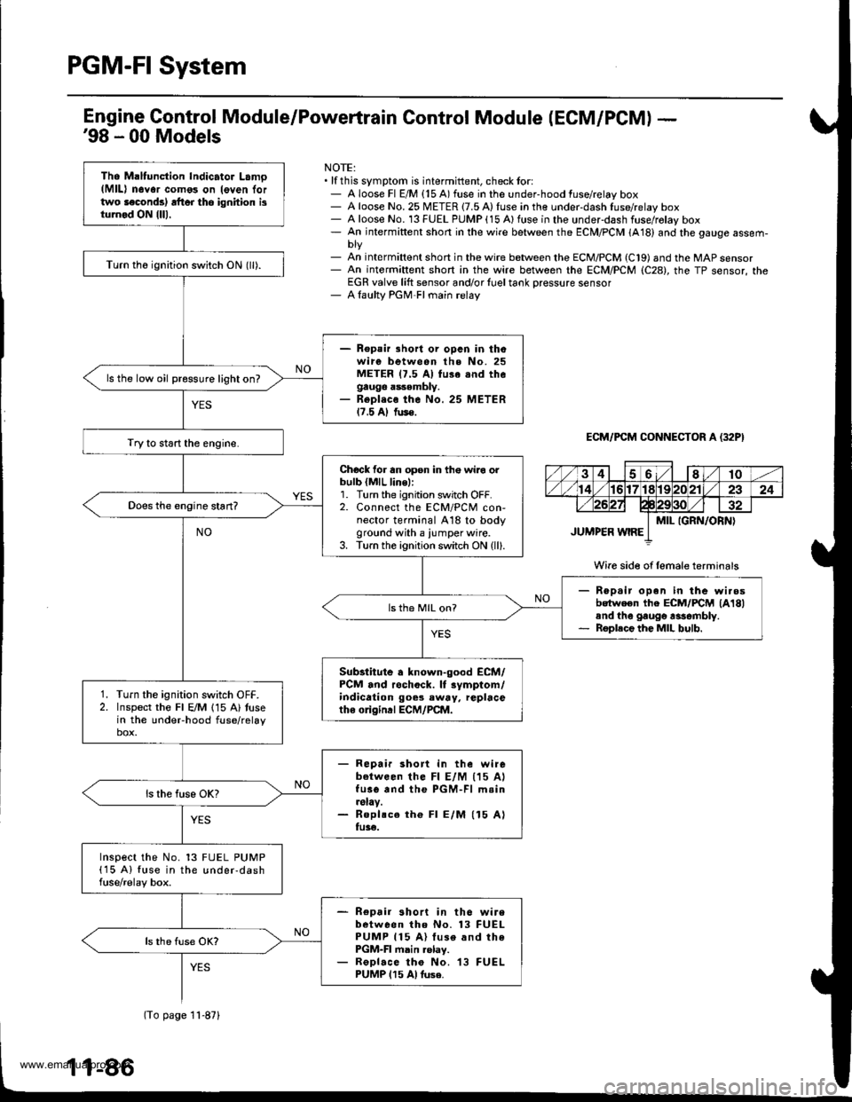
PGM-FI System
Tho Maltunction Indicator Lamo(MlL) n6Yor como3 on leven lortwo laconds) rft6r tho ignhion isturnod ON {lll.
Turn th6 ignition switch ON (ll).
- Repair lhort or opcn in thowire between the No. 25METER 17.5 Al fu3e snd thegauge assembly.- Repl.co the No. 25 METER17.5 Al fus€.
ls the low oil pressure light on?
Try to start the engine.
Chock for an opsn in th€ wiro orbulb {MlL line,:1. Turn the ignition switch OFF.2. Connect the ECM/PCM con-nector terminal A18 to bodyground with a iumper wire.3. Turn the ignition switch ON (ll).
Rep.ir open in the wi.osbotween the ECM/FCM lA18land the gaugo rasombly.Roplece the MIL bulb.
ls th6 MIL on?
Substitute a known-good ECM/PCM and rochock. lf rymptom/indication goes eway, replacetho o gind ECM/PCM.
Turn the ignition switch OFF.Inspect the Fl E/M 115 A) tusein the undeFhood fuse/relaybox.
- Repair short in the wirebetween lhe Fl E/M (15 AlfusG and the PGM-Fl m.in.slay.- Roplsce th€ Fl E/M (15 Alfu3€.
Inspect the No. 13 FUEL PUMP(15 A) fuse in the under-dashfuse/relay box.
- Repair short in th6 wirebetween tho No. 13 FUELPUMP 115 A) luse and thePGM-FI main .elay.- ReDlace tho No. 13 FUELPUMP 115 Al tuse.
Engine Gontrol Module/Powertrain Control Module (ECM/PCM) -'98 - 00 Models
NOTE:. lf this symptom is intermittent, check tor:- A loose Fl E/M {15 A) fuse in the under-hood fuse/relay box- A loose No. 25 METER {7.5 A) fuse in the under-dash fuse/relay box- A loose No. 13 FUEL PUMP (15 Alfuse in the underdash fuse/rolay box- An intermiftent short in the wire between the ECM/PCM (A18) and the gauge assem-
- An int€rmiftent short in the wire between the ECM/PCM (C19) and the MAP sensor- An intermiftent short in the wire between rhe ECM/PCM (C28), the TP sensor, theEGR valve lift sensor and/or {uel tank Dressure sensor- A laulty PGM-FI main relay
ECM/PCM CONNECTOR A (32P}
Wire side of female terminals
(To page 11-871
www.emanualpro.com
Page 364 of 1395
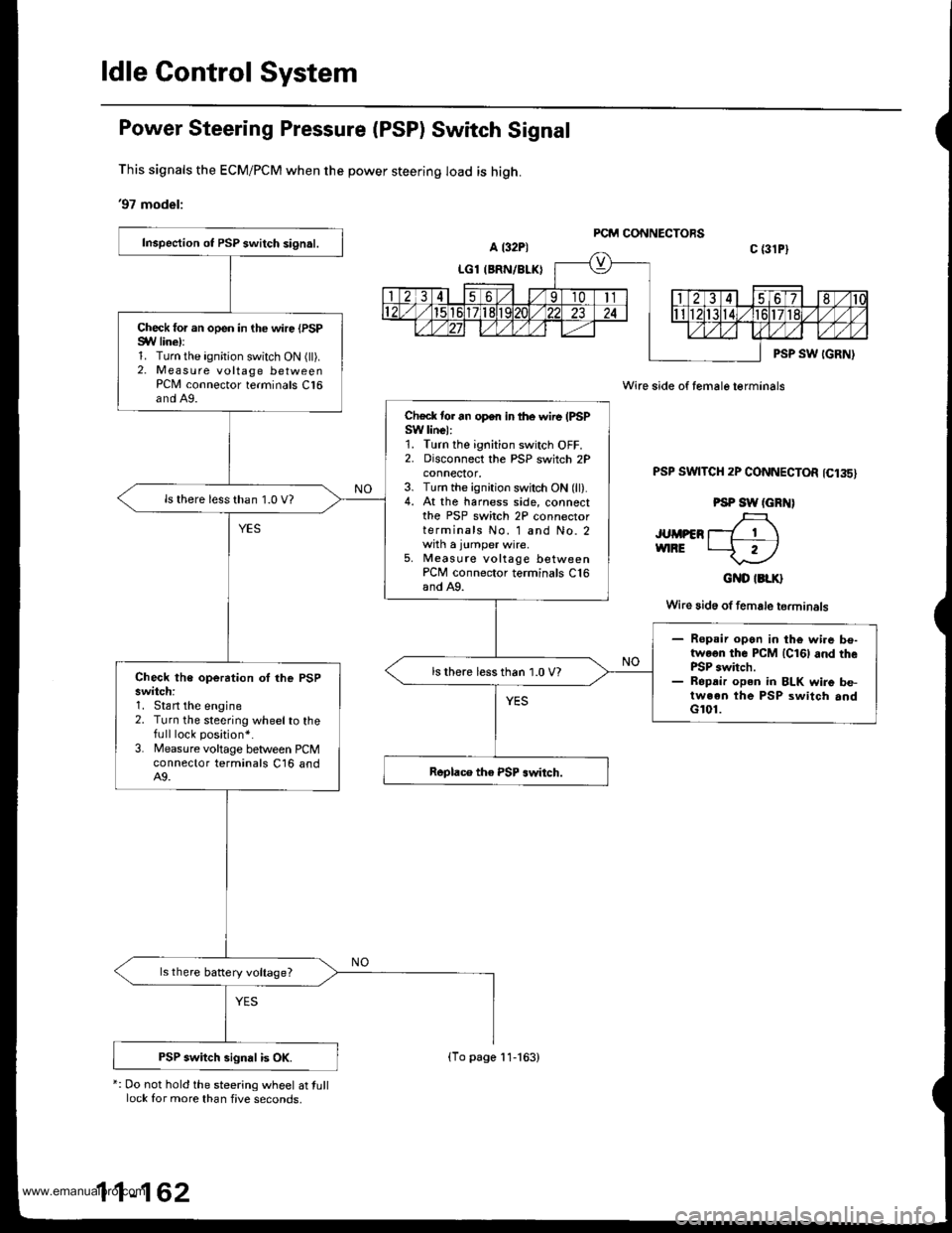
ldle Gontrol System
Power Steering Pressure (PSP) Switch Signal
This signals the ECM/PCM when the power steering load is high.
'97 model:
*: Do not hold the steering wheel at tulllock for more than five seconds,
Wire side of female terminals
PSP SWTTCH 2P CONNECTOR 1C135)
PSP SW (GRN)
JUMPER T_7 1 \vnRE t--f r)
GND IBLK}
Wire 3id6 of female terminals
Inspection ot PSP switch signal.
Check for an open in the wire {PSPSYV line):1. Turn the ignition switch ON (ll).2. Measure voltage betweenPCN4 connector terminals C16and A9.
Check tor an open in lhe wire (PSPSW linel:1. Turn the ignition switch OFF.2. Disconnect the PSP switch 2Pconnecror,3. Turn the ignition switch ON (ll).4. At the harness side, connectthe PSP switch 2P connectorterminals No. 1 and No. 2with a jumper wire.5, Measute voltage betweenPCM connector terminals C16and A9.
ls there less than 1.0 V?
- Ropsir open in the wi.e be-twoon the PCM lcl6l and thePSP switch.- Ropdir open in BLK wire be-tween the PSP switch andG101.
ls there less than 1.0 V?Check the operation oI lhe PSPswitch:1. Stan the engine2. Turn the steering wheelto thefull lock position*.
3. Measure voltage between PCMconnector terminals C16 andA9.
ls there battery voltage?
PSP switch signal is OK.(To page 11-163)
www.emanualpro.com
Page 366 of 1395
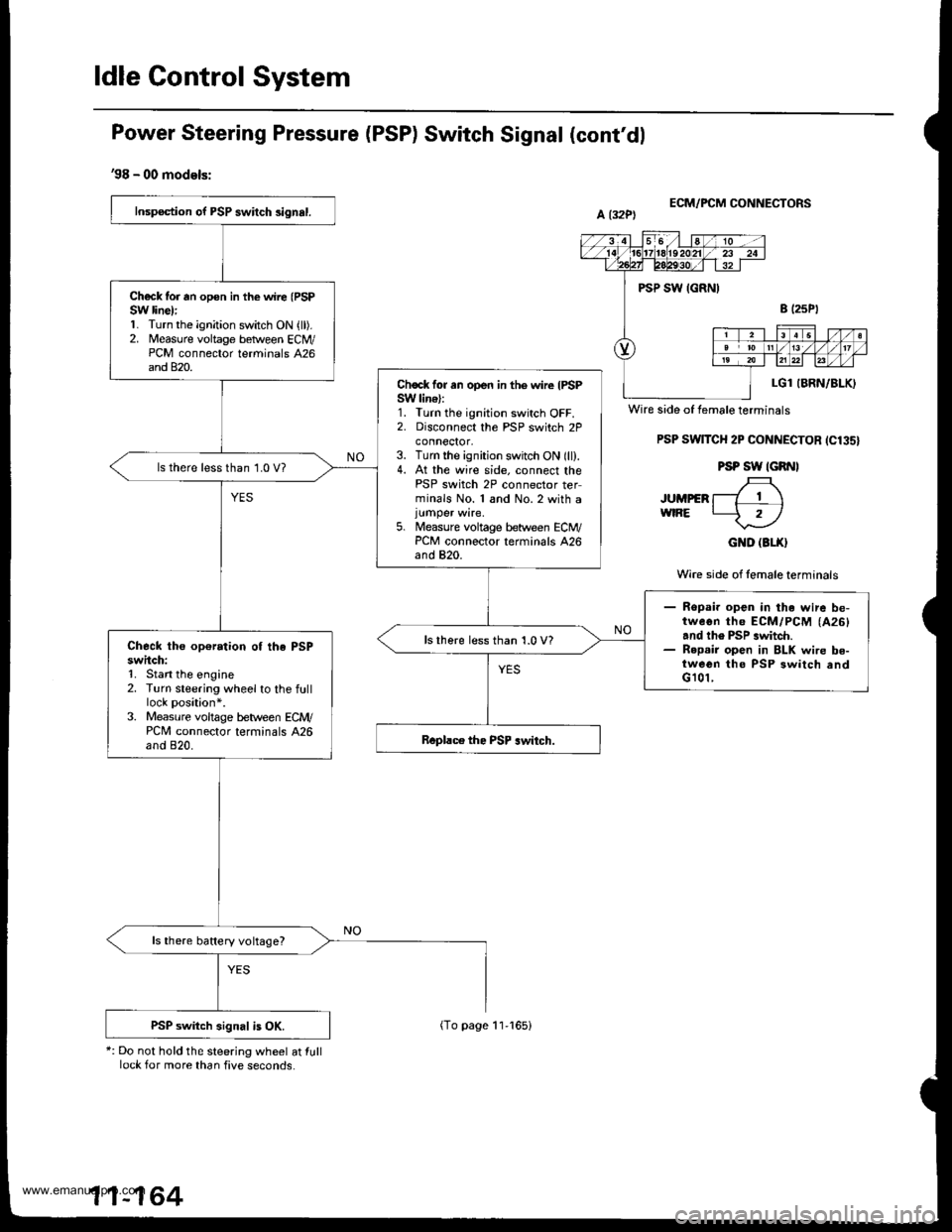
ldle Control System
Power Steering Pressure (PSP) Switch Signal (cont'dl
'98 - 00 models:
*: Do not hold the steering wheel at lulllock for more than five seconds.
ECM/FCM CONNECTORS
PSP SwlTCH 2P CONNECTOR ICl35}
PSP SW IGRNI
JUMpER f-7 T \wtRE L-5 rl
GND (3LX}
Wire side of lemale terminals
Inspection of PSP swilch 3ignal.
Ch€ck tor rn opon in the wire (PSP
SW line):1. Turn the ignition switch ON {ll).2. Measure voltage betlveen ECM/PCM connector terminals 426and 820.
Chock for an open in the wire IPSPSW lin€):1. Turn the ignition switch OFF.2. Disconnect the PSP switch 2Pconnector,3. Turn the ignition switch ON (ll).4. At the wire side. connect thePSP switch 2P connector terminals No. 1 and No.2 with a
5. Measure voltage between ECM/PCM connector terminals 426and 820.
ls there less than 1.0 V?
- Ropai. open in the wire be-tweon th6 ECM/PCM (A26)
and th6 PSP .witch.- R6p.ir open in BLK wire be-tween tho PSP 3witch andG 101,
lsthere less than 1.0 V?Check the op€ration of the PSPswitch:1. Stan the engine2. Turn steering wheel to the fulllock position*.3. Measure voltage b€tween ECM/PCM connector terminals A26and 820.
ls there battery voltage?
PSP switch signal is OK.
Wire side of female terminals
11-164
(To page 11-165)
www.emanualpro.com
Page 384 of 1395
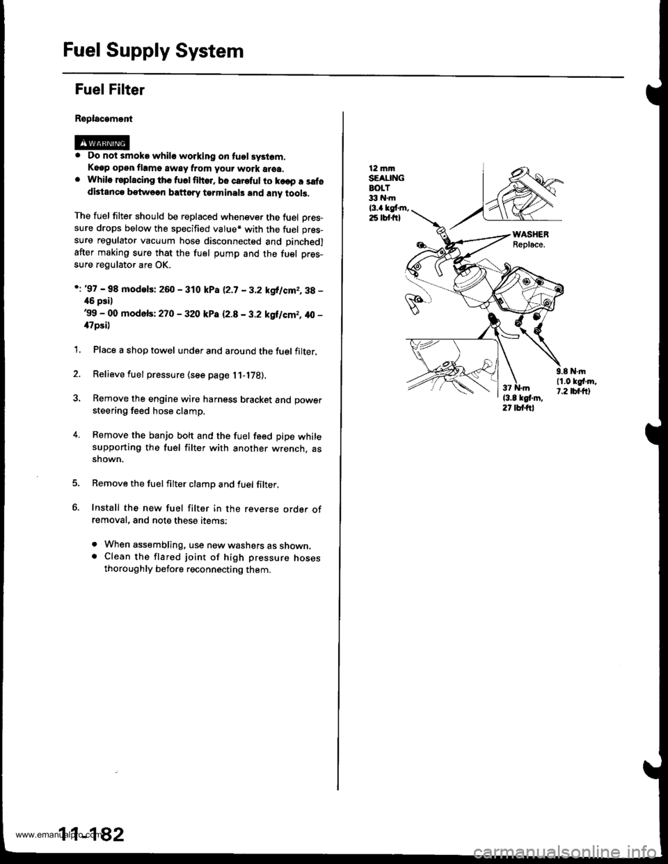
Fuel Supply System
Fuel Filter
Replacamont
. Do not smoke whilo working on tuol syslom,Keep open flame away from your work area.. While rsplscing ths fuolfihor. bo careful to ko€p a safedistanca betweon baftsry tarminals and any tools,
The fuel filter should be replaced whenever the fuel Dres-sure drops below the specified value* with the fuel pres-
sure regulator vacuum hose disconnected and pinchedl
after making sure that the fuel pump and the fuel pres-
sure regulator are OK.
i: '97 - 98 modelsi 260 - 310 kPa 12.7 - 3.2 kgllcm2,3g -
46 psil'99 - 00 mod6fs: 270 - 320 kP8 12.8 - 3.2 kgilcm2, 40 -
il7psi)
1, Place a shop towel under and around the fuel filter.
2. Relieve fuel pressure (see page l1-l7B).
3. Remove the engine wire harness bracket and power
steering feed hose clamp.
4. Remove the banjo bolt and the fuel feed pipe whilesupporting the fuel filter with another wrench. assnown.
Remove the fuelfilter clamp and fuel filter,
Install the new fuel filter in the reverse orde. ofremoval, and note these items:
. When assembling, use new washers as shown.. Clean the flared joint of high pressure nosesthoroughly before reconnecting them.
11-182
12 mmSEAUNGBOLT33 hl.m
l3.a kgt m,25 lbt frl
9.8 N.|n11.0 kgf'm,t.2 tbt.ftl
www.emanualpro.com
Page 517 of 1395

Automatic Transmission
Special Tools . 14'2OescriptionGeneral Operation . .... 14 3Power Flow . . .. '14_6
Electronic Control System .. .. . . .. .14_15Hydraulic Control .. 14 24Hydraulic Flow....-....... .. . .... .. .. . 14_29Lock'up Syslem .. .'t4'39Electrical SystemComponenl Locdlrons 14 45
PCM Circuil Dragram (A/T Control Svstem)'97 Model ....................... . . .. - . ... .14-46'98Model ................. . ... .. .. .1450'99 00Models.... . .... . . . 1452
PCM Terminal Voltage/Measuring ConditionsA"/T Control System-'97Model ...... ..14'48A,/T Control System -'98 00 Models . . .. . . 14 54
Troubleshooting Procedures .. ..... ... - 14_56Svmotom to comoonent CharlEiectr,cal Syslem -'97 Model . . 14 60Electrical System -'98 - OO Models . .. . . 14_62Electrical Troubleshooting ('97 Model)Troubleshooting Flowaharts .... ..... . .. . . 14_64
Electrical Troubleshooting ('98 - 00 Models)Troubleshootinq Flowclt"n" .... . ....- . .14-93ElectricalTroublesliooting('99 00Models)Troubleshootino FlowchartO/D OFF Indicator Light Does Not Come On 14 131
O/D OFF Indicator Liaht On ConstantlY . . . .1!-132O/D OFF Indicator Light Does Not Come OnEven Though O/D Switch ls Pressed . .... - 14_133
Lock up Control Solenoid Valve A,/B AssemblyTest....................-......... . .14-135Replacement . .ll_135Shifr ControlSolenoid Valve Ay'B Assembl,Test .............................. . .. 14-136
Replacement..............- . .14'136Linear Solenoid AssemblYTest.............................................. .. .... . 14_137Replacement .. . 14138Marnshaftlcountershafl Speed SensorsReplacement ...-... 14_138A/T Gear Position SwitchTest ..........................-... . .. 14-139ReplacementA/T Gear Positionlndicator.................. 14-140
Valve Eodynepair ............................... ..... . . .. - . .. ... 14 192
Assembly .................... .. 1{_193
Valve CapsDesciiption....-........................ .. ...... 14194
tnspeition ................... .. 14' 195
N4ain Valve BodyDisassembly/lnspection/Reassemblv - ...... .. 14_196
Secondarv Valve BodYDisassemblv4nspectron/ReassemblY .. . 14 198
Reoulator Valve Bodvbisassembtv,lnspiction/Reassemblv . 14199
Servo EodvDisassembly/lnspection/Reassembly ... ....14'200
Lock'uo Valve BodYDis;ssembly/lnspection/Reassembly .... . 14_201
MainshaftDisassembly/lnspection/Reassembly .. .. .. ..14'202
Inspection ....-.............. ..11_203
Sealing RingsReilaceient ...... ..... . 14'204
CountershaftDisassembly/lnspection/Reassembly .. . . . . . 11-205
Disassembly/Reassemb|y . . ........ ...... . .. 14_206Inspedron ................ . .... . 14 207
One wav ClutchDisassembly/lnspection/ReassemblY ... 11_209
Sub-shaftDisassembly/lnspection/Reassembly ... . .. . 14-210
oisassembly/Re6ssembly . . ... .-...... . . ..14-211
Sub-shaft BearingsReplacement .......14'212
Clutchllfustrated Index .......... . . .14-213
Disassembly .... .. .....14-216Reassembfy .... . .. .. . 14'218
Differentialllfustrated Index " 14-222Backlash Inspection . .... . .14'223
Bearing Repiacement .. 11-223
Differe-ntial Carrier Replacement .. .. . . . .. ..11-2?4
OifSeal Replacement. . .. 14'225
Side Clearance lnspection . . - .. ... . - ...... . .. 11'226
Transmission Housing BearingsMainshaJVCountershaft EearingsRepfacement .......14221Sub'siralt Eearing Replacement . . . . . . . . . ..11'224
Toroue Converter Housing BearingsMainshattEearing/OilSe6lReplacement . .. l4229
Countershaft Bea;ing Replacement.. .... .. ..14-230
Input Test - '97 - 98 ModelsInput Test '99 - 00 Models
Symptom to-Component ChartHydraulic System ...............
Checking
Removal ...,lllustrated Index (4WD)
Interlock SystemInterlock ControlUnit lnputTest. -..... -.. .... . - 14 144* Key Interlock Solenoid Test .- .. . . . - . . . ..... 14_146* Shift Lock Solenoid Test ..............-.-. . .. . ... .... 14 147*Shift LockSolenoidReplacement...... .. . .. .. 14 148* park pin Switch Test ......... 14 119' Park Pin Switch Replacement- '97 - 98 Models ....... 14-150* Park Pin Swirch/Over Drive (O/Di SwitchReplacemenl '99-00Models . .. 14_151over-Drive (O/D) Switch {'99 00 [4odels]Test........_..................... .......14-152Hydr.ulic System
..............._............... t4 142.................................. 14-143
Control Lever AssemblyR6placement ......,.,Reverse ldler Gear
lllustrated lndex
.......... 14-230
14 231
11-231
1nsta1|ation ..................Park StopInspeclion/AdjustmenlTransfer AssemblY.......14.232
RoadTest.............-.... ........ .StallSpeedTest ....._........................ ....... 14-159Fluid Level......_................... 14'160
Disessembly .................... 14-235Transfer Drive Gear BearingReplacementTrans{er Driven Gesf Shaft BearingReplacementTransfer Housing Roller BearingReplacementTransfer Cov€r A Bearing Outer RaceReplacementTransfer Housing Bearing Outer RaceReplacement ......-..,,,,,.....ReassemblvTransmassaonBeassembly ... -.. .... .14 250
Torque Converier/Drive Plate . .-. .... .. . ... .....14_258
Transmissionlnstatlation .................. ....... 14'259
Cooler Flushing . . ......11-261ATF Cooler HosesConnection.................. ....... 14-266I Shift LeverRemoval/lnstallation . .. 14'261
Disassemblv/Reassemblv - '97 - 98 Models . . 14_264
Disassembli/Reassemblv -'99 - 00 Models . 14-269
Over'Orive (O/D) Switch WireClearanceAdjustment. - ... . . . .. .. . 14'270
Detent Spring Replscement . . -.. ... .14'271*Shift CableAdiustment ....... 14'272
Repfacement.............. . 11'273
14 15711-237
11-237
14-238
$-234
11-23914-240
Transmigrion
Inspeclron ....., ...........Transfer AssemblyRemova1,.,,,..............,lnstallalion ........... .. ...Transmission
14 164
14-16514,167
14-169
End Cover/Transmissio . 14'174Transmission Housing .... ... .. . . .... .. 14-176Torque Converter Housingly'alve Body.. - ... -. 14 178
lllustrated lndex (2WD)End Cover/Transmissio ....... 14 180Transmission Housing . . ... . .. .... ... 14'182Torque Convener Housing/r'alve Body ......- 14-184
End CovefRemovat ...................... ....... 14'186Transmission HousingRemoval ...................... .. 14_188Torque Convener HousingA/alve BodYRemovat ................-..... .-..... 14-190
www.emanualpro.com
Page 580 of 1395
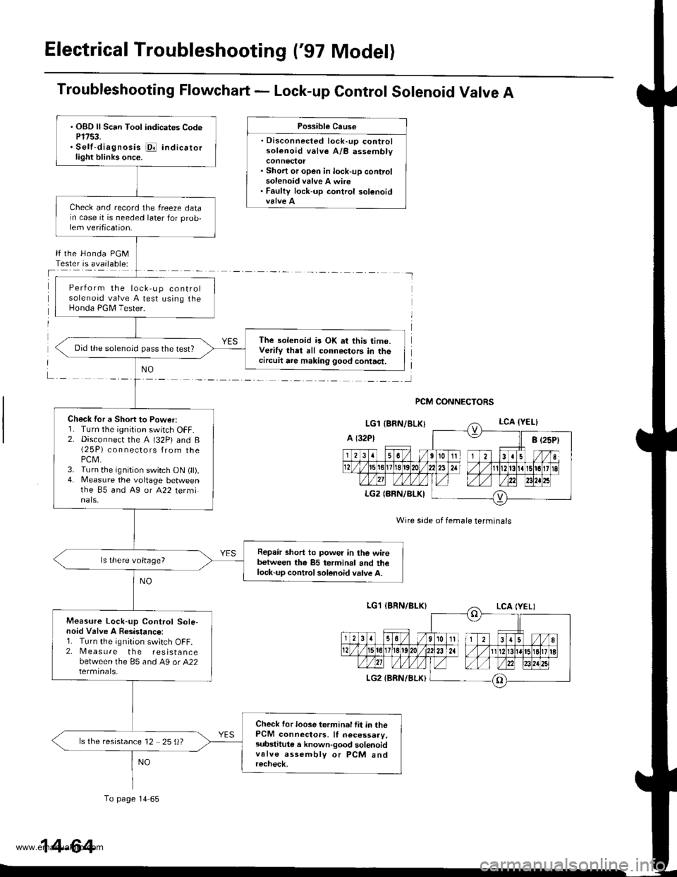
Electrical Troubleshooting ('97 Model)
Troubleshooting Flowchart - Lock-up Control Solenoid Valve A
Possible Cause
. Disconnected lock-up controlsolenoid valve A/B assembly
. Short or open in lock-up controlsolenoid valve A wire. Faulty lock-up control solenoid
lf the Honda PGMTester is available:
NO
Wire side of female terminals
PCM CONNECTORS
. OBD ll Scan Tool indicates CodeP1753.. Self-diagnosis i@ indicatorlight blinks once.
Check and record the freeze datarn case it is needed later for prob-lem verification.
Perform the lock,up controlsolenoid valve A test using theHonda PGM Tester.
The solenoid is OK at this time.Verify that all connectors in thecircuil are making good contact,
Did the solenoid pass the test?
Check for a Short to Power:r. I urn rne tgntUon swttch ut-f.2. Disconnecr the A (32P) and B(2 5P) connectors from thePCM.3. Turn the ignition switch ON (ll).4. Measure the voltage betweenthe 85 and A9 or A22 terminals.
Repair short to power in the wirebetween the 85 terminal and thelock-up control solenoid valve A.
ls there voltage?
Measure Lock-up Control Sole-noid Valve A Resistance:1. Turn the ignition switch OFF.2. Measure the resistancebetween the 85 and A9 or A22
Check for loose terminal fit in thePCM connectors, ll necessary,substitule a known-good solenoidvalve assembly or PCM andrecheck,
ls the resistance 12 25 ()?
To page 14 65
14-64
www.emanualpro.com