connector a HONDA CR-V 1999 RD1-RD3 / 1.G Workshop Manual
[x] Cancel search | Manufacturer: HONDA, Model Year: 1999, Model line: CR-V, Model: HONDA CR-V 1999 RD1-RD3 / 1.GPages: 1395, PDF Size: 35.62 MB
Page 594 of 1395
Electrical Troubleshooting {'97 Model)
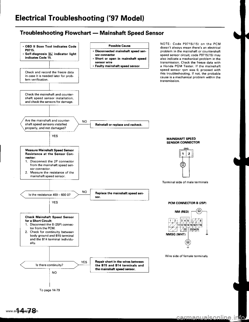
Troubleshooting Flowchart - Mainshaft Speed Sensor
Po$ible Cau3o
. Disconnocted mainshaft speod sen-sot connectot. Short or open in mainsh.ft sp6ed
' Faulty meinshaft spoed sensor
NOTE: Code P0715115) on the PCMdoesn't always mean there's an electricalproblem in the mainshaft or counlersharlspeed sensor circuit; code P0715(15) mayalso indicate a mechanical problem in thetransmission. Check the freeze data witha Honda PGM Tester. lf the mainshaftspeed sensor rpm was 0, proceed withthis troubleshooting. lf not, the probablecause is a mechanical problom within thetransmission,
MAINSHAFT SPEEOSENSOR CONNECTOR
_E_
ItiT,ll-F=r
9t
LJ
Terminal side of male terminals
PCM CONNECTOR B {25P'
Wire side of female terminals
. OBD ll Scan Tool indic.t6 Codem715.. Self-diagnosis E indic.tor lightindicatag Code 15.
Check and record the freeze datain case it is needed later {or prob,lem verification.
Check the mainshaft and counter-shaft speed sensor installation,and checkthe sensors for damage.
Are the mainshaft and counter-shaft speed sensors installedproperly, and not damaged?Reingtall or reolace and recheck.
Meaaure MaiNhatt Spoed Sen3orR6sist!nce at the Sensor Con-necaor:1. Disconnect the 2P connectorfrom the mainshaft speed sen-sor connector.2. lreasure the resistance of themainshaft speed sensor.
ls the resistance 400 - 600 O?
Check Mainahaft Speed Sensortor a Short Circuit:1. Disconnect the B (25P) connec-tor lrom the PCM.2. Check for continuity betlveenbody ground and 815 terminaland the 814 terminal individu-
ReDair short in the wir€6 b€t reenthe 815 and 814 torminals andthe mainsh!ft sp€ed sensor.
To page l4-79
14-78
www.emanualpro.com
Page 595 of 1395
From page 14'78
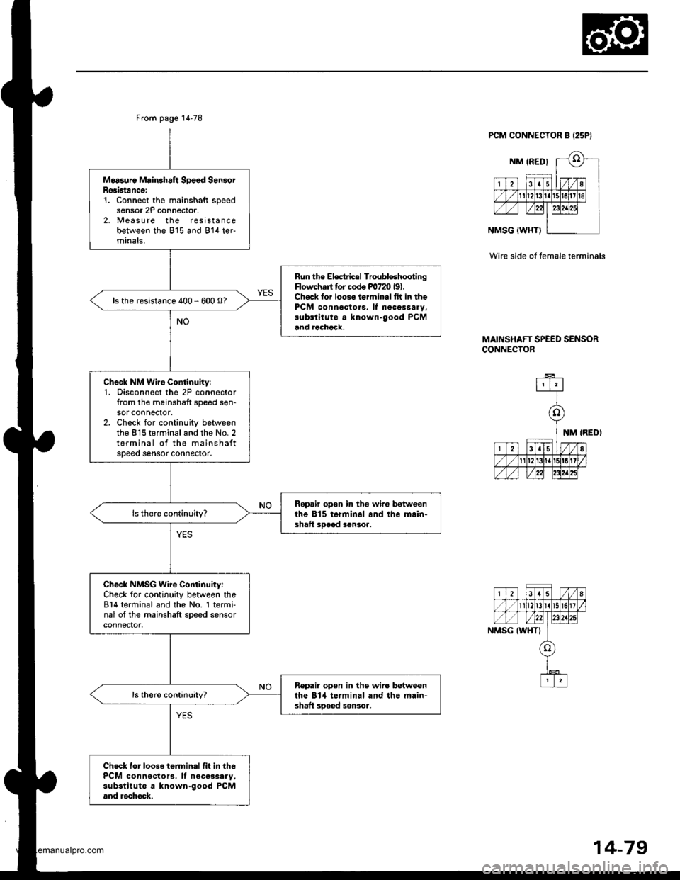
Moasuro Mrin3haft Spoed SanlorResktanco:1. Connect the mainshaft speedsensor 2P connector,2, Measure the resistancebetween the 815 and 814 ter-minals,
Run the Electricrl TroubloshootingFlowchs tor codo m72O l9l.Chock for loo3e torminal fh in thePCM conn6cto.s. It necessarY,substitute a known-good PCMand rochgck.
ls the resistance 400 - 600 O?
Check NM Wiro Continuity:1. Disconnect the 2P connectorfrom the mainshaft speed sen-sor connector.2. Check for continuity betweenthe 815 terminaland the No.2terminal of the mainshaftspeeo sensor conneoor.
Ropair open in the wir6 betw€onthe 815 terminal and the main-shaft sDood $nsoa.
Check NMSG Wire Continuity:Check for continuity between the814 terminal and the No. 1 termi-nal of the mainshaft speed sensorconnector.
R€pai. opon in the wi.o betweenthe Bltl terminal and tho main'3haft sDe€d sensoa,
Ch.ck lor loos. t6rminallit in thePCM connecto13, lf neca3sary,substitute a known-good PCMand rochock.
PCM CONNECTOR B {25P}
Wir€ side of female terminals
MAINSHAFT SPEED SENSORCONNECTOR
14-79
www.emanualpro.com
Page 596 of 1395
Electrical Troubleshooting ('97 Modell
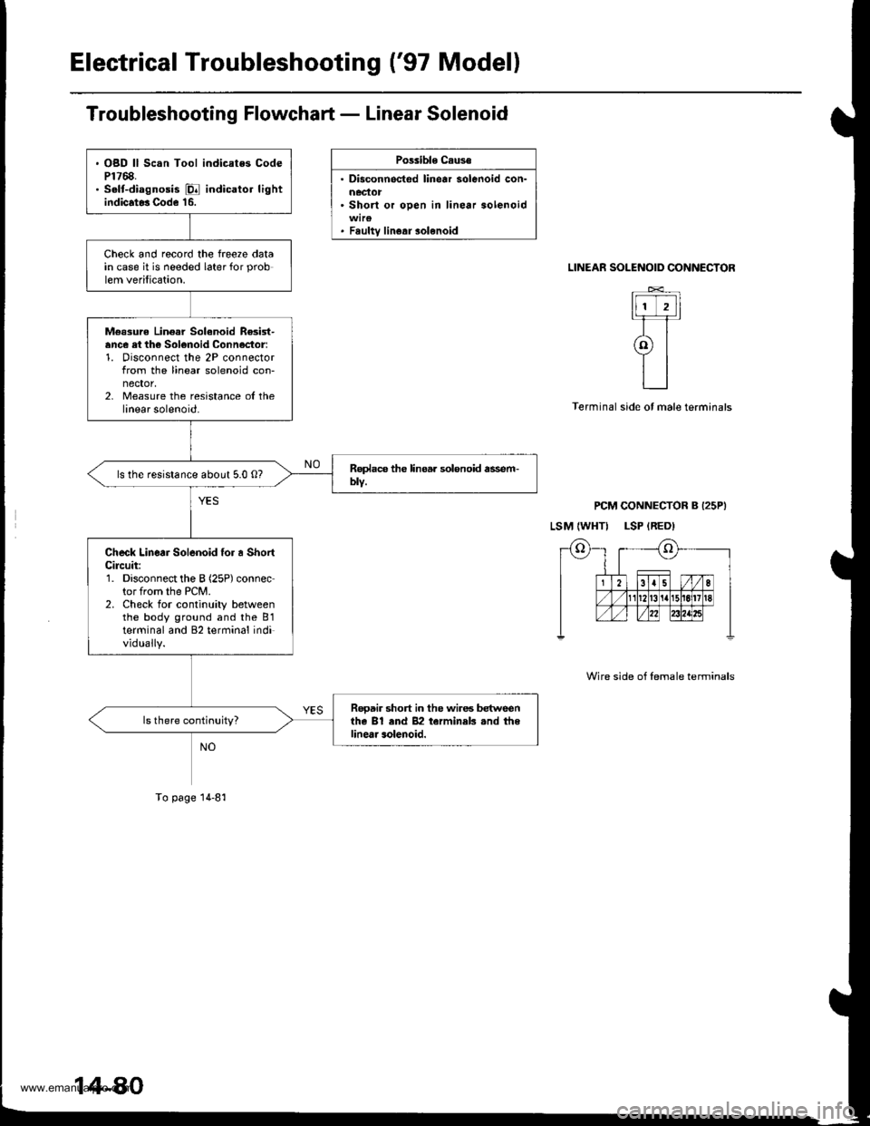
Troubleshooting Flowchart - Linear Solenoid
Possible Caus€
. Disconnocted linear solenoid con-
. Short or oDen in linear solenoid
. Fsultv linear solenoid
SOLENOID CONNECTOR
t-TTI�t]]lt
tl I ? rl-T�r
atll
L_l
PCM CONNECTOR B I25PI
LSM {WHTI LSP {RED)
LINEAR
Terminal side ot male terminals
Wire side of lemale terminals
. OBD ll Scan Tool indicates CodeP1768.. S.lt-diagnosis E indicator lightindicat* Code 16.
Check and record the freeze datain case it is needed later for prob
lem verification.
M€ssurc Linear Solanoid Re3ist-ance ei th€ Solonoid Connoctor:1. Disconnect the 2P connectorfrom the linear solenoid con-nector,2, Measure the resistance ol thelinear solenoid.
ls the resistance about 5.0 O?
Check Linear Solenoid {or a ShortCileuit:1. Disconnect the B (25P) connector from the PCM.2. Check for continuity betweenthe body ground and the B1terminal and 82 terminal individually.
Rooair short in the wires betweenthe Bl end 82 terminek .nd thelinear solenoid.
To page 14-81
www.emanualpro.com
Page 597 of 1395
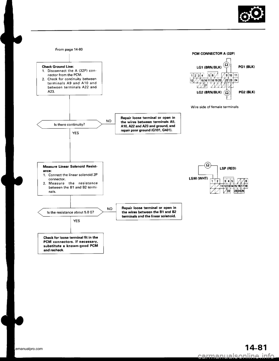
Ch€ck Ground Lin€:1. Disconnect the A (32P) con-nector from the PCM.2. Check lor continuity betweenterminals Ag and A10 andbetween terminals A22 andA.23.
Repair loose terminal or opon inth€ wires between terminals A9,A10, A22 and A23 and g.ound, andrepair poor ground lG101, G4011.
Measure Linear Solenoid R*ist-
ance:1. Connect the linear solenoid 2P
connector.2. Measure the resistancebetween the 81 and 82 terminals,
Ropair loos€ terminal or op6n in
the wiles between th€ 81 and 82
l6rminals and the linear solenoid.ls the resistance about 5.0 0?
Chock lor loose tarminalfit in thePCM connectors. lf necosaarv,subsiituto a known-good PCMand recheck.
PGl IBLKI
PG2 (ALKI
Wire side of temale terminals
14-81
www.emanualpro.com
Page 602 of 1395
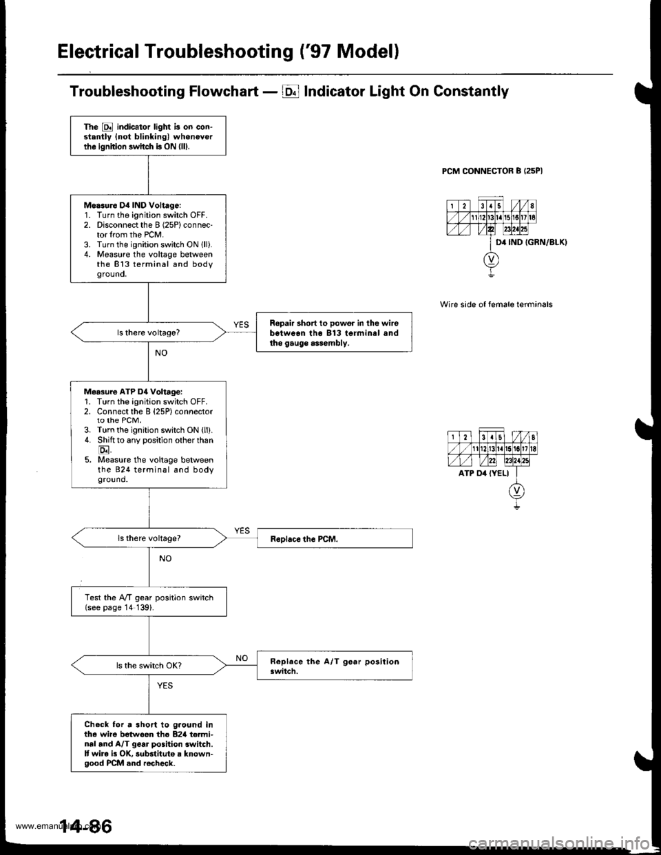
Electrical Troubleshooting ('97 Modell
Troubleshooting Flowchart - E Indicator Light On Constantly
PCM CONNECTOR B I25PI
IGRN/8LKI
Wire side of temale terminals
The E indicator light is on con-stantly {not blinking) wheneverthe ignition switch b ON (lll.
Measure D4 IND Voltage:'1.
2.
3.4.
Turn the ignition switch OFF.Disconnect the I (25P) connec-tor lrom the PCM.Turn the ignition switch ON lll).Measure the voltage betweenthe 813 terminal and bodygrouno,
Ropair short to powor in the wirebetwean tho B13 terminal andtho gauge assembly.
Maa3ure ATP D4 Voltage:1. Turn the ignition switch OFF.2. Connect the B (25P) connectorto the PCM.3. Turn the ignition switch ON (ll).
4. Shiftto any position other than
E.5. Measure the voltage betweenthe 824 terminal and bodyground.
Test the lVT gear position switch(see page '14 139).
Check lor a short to g.ound inthe wire betwoen tho B2rl te.minal and A/T gear position switch.It wira i3 OK, substitute a known-good PCM and r€check.
www.emanualpro.com
Page 603 of 1395
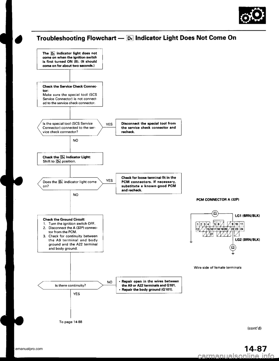
Troubleshooting Flowchart - E Indicator Light Does Not Come On
PCM CONNECTOR A {32PI
Wire side ot temale terminals
LGl IBRN/BLKI
LG2 (BRN/BLKI
(cont'd)
The E indicator light doos notcomo on whon the ignition switchis first turned ON {lll. (lt shouldcome on lor about two aaclnd!.I
Check the Sorvice Check Connec-toriMake sure the special tool 1SCSService Connector) is not connect-ed tothe service check connector,
Di3connect the spccial tool tromthe servica chock connoctor andrechsck.
ls the specialtool (SCS ServiceConnectorlconnected to the ser-vice check connector?
chock th. El Indicator Light:Shift to E position.
Ch6ck for looie terminal fit in thePCM connoctors. ll nocesssry,sub.titule a known-good PCMand rechock.
Check the Ground Circuit:1. Turn the ignition switch OFF.2. Disconnect the A {32P)connec-tor from the PCM.3. Check for continuity betweenthe A9 terminal and bodyground and tho A22 terminaland body ground.
R€pair opon in the wire3 betweenthe Ag or A22 torrninab and G101.Repair the body ground (G1011.
To page 14-88
14-87
www.emanualpro.com
Page 604 of 1395
Electrical Troubleshooting ('97 Modell
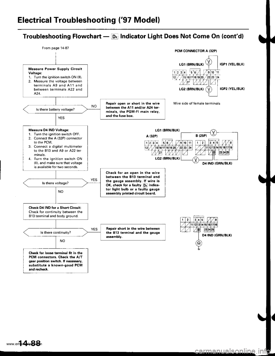
Troubleshooting Flowchart - E Indicator Light Does Not Gome On (cont'dl
IYEL/BLK)
IGP2 IYEL/BLK)
Wire side of female terminals
From page 14-87
Measure Power Supply circuitVoltage:1. Turn the ignition swatch ON (ll).
2. Measure the voltage betweenterminals Ag and A11andbetween terminals A22 andA�24.
Repair open or short in the wirebotw€on the A11 and/or A24 ter-minals, the PGM-FI main relav,and ih6 fuse box.
ls there baRery voltageT
Measur€ Dil INO Voltag6:L Turn lhe ignition switch OFF.2. Connect the A 132P) connectorto the PCM.3. Connect a digital multimeterto the 813 and A9 or A22 termtnals,4. Turn the ignition switch ON(ll), and make sure that voltageis available for two seconds.
Check for an op€n in the wirebetween the 913 terminal andthe gauge assembly. lf wire isOK. check tor a faulty E indica-tor lighl bulb or a taulty gaugea$embly printed circuil bo.rd.
Check D4IND tor a Short Circuit:Check for continuity between the813 terminal and body ground.
Ropair short in the wiro betweenthe 813 lerminal and the gaugeassembly.
Check tor loose terminal frt in thePCM connector3. Chock the A/Tgear position switch. ll necessary,substitute a known-good PCMand recheck.
14-88
www.emanualpro.com
Page 605 of 1395
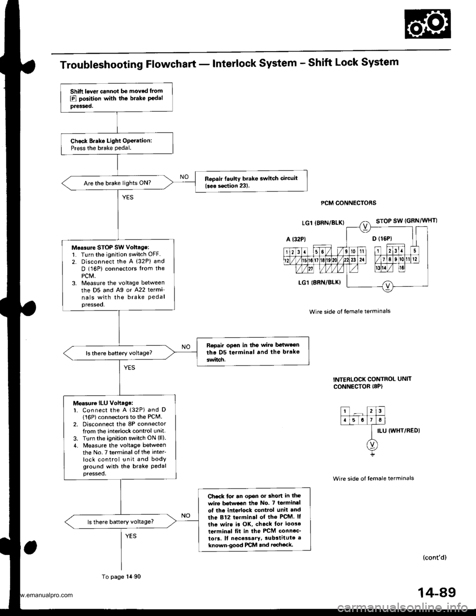
Troubleshooting Flowchart - Interlock System - Shift Lock System
PCM CONNECTORS
Wire side of lem6le termanals
INTERLOCK CONTROL UNIT
CONNECTOR I8P)
ILU IWHT/REDI
(cont'd)
Shift lever cannot be moved from
E] position with the brake P€delpreiseo.
Chock Brake Light Operation:Press the brake pedal.
Repsir fauhy brake switch circuit
{seo s€ction 231.Are the brake lights ON?
M€asure STOP SW voltage:l� Turn the ignition switch OFF.
2. Disconnect the A (32P) and
D (16P) connectors lrom thePCM.3. Measlre the voltage between
the D5 and Ag or A22 terma
nals with the brake Pedalpressed,
Repair opon in the wi.e be{w.enthe D5 terminal and the br.ke
switd!.
Measur€ ILU vohage:1. Connect the A {32P) and D
116P) connectors to the PCM.2. Disconnect the 8P connectorfrom the interlock control unit
3. Turn the ignition switch ON (ll).
4. Measure the voltage betweenthe No.7 terminalofthe inter
lock control unit and bodyground with the brake Pedalpressed,
Ch€ck for an opon or thon in the
wire Mwoon tho No. 7 terminrl
of the inte ock control unit and
the 812 termin.l of the PcM. ll
the wirs is OK, check tor loo3e
terminal fit in the PCM connec_
to13. ll nece3sary,3ubstitute a
known-good PCM and rechock.
ls there battery voltage?
To page 14 90
14-89
www.emanualpro.com
Page 606 of 1395
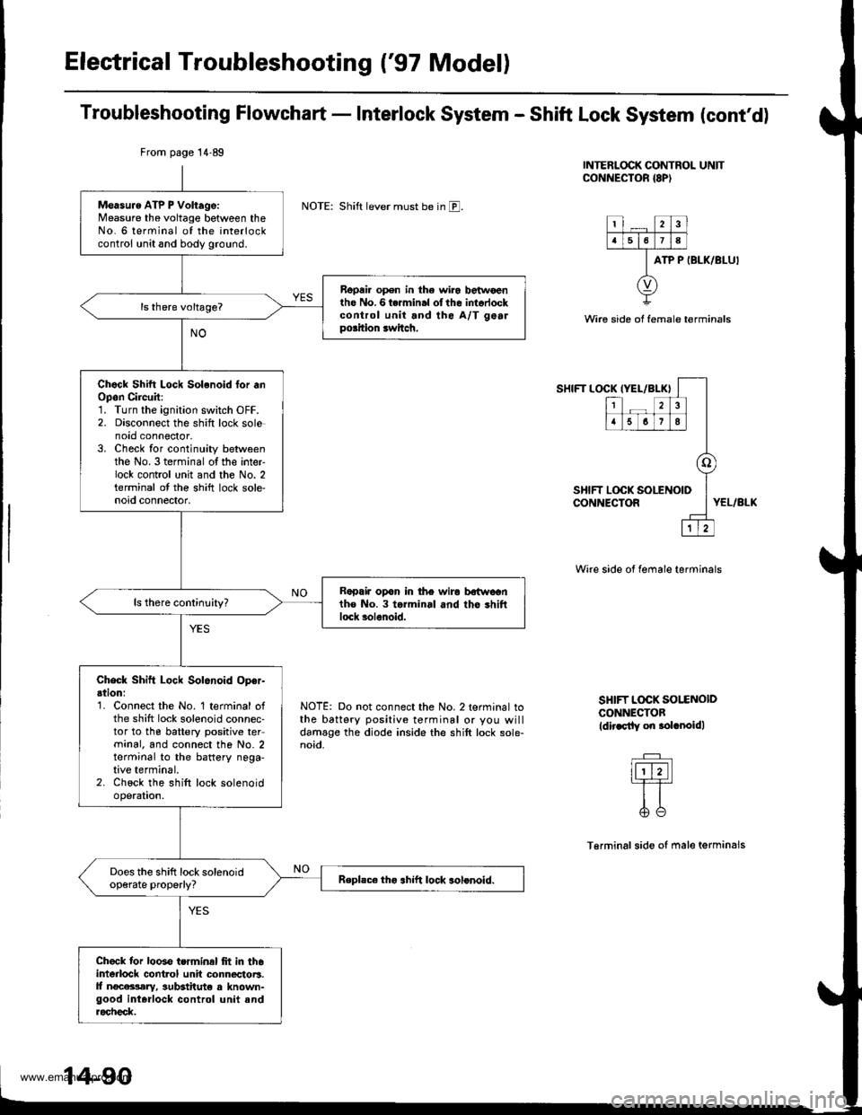
Electrical Troubleshooting ('97 Model)
Troubleshooting Flowchart - Interlock System - Shift Lock System (cont'd)
INTERLOCK CONTROL UNITCONNECTOR {8P)
NOTE: Shift lever must be in E.
ATP P IBLK/BLU'
Wire side ot female terminals
SHIFT LOCKIYEL/BLK}
12
5678
o
LOCK SOLENOID
1
SHIFT LOCK !CONNECTORYEL/BLK
NOTE: Do not connect the No. 2 terminal tothe battery positive terminal or you willdamage the diode inside the shift lock sole-noid.
Wire side of female terminals
SHIFT L@K SOI.ENOIDCONNECTOBldir.sily on .olrnoidl
Terminalsido of male terminals
From page 14.89
Measu.e ATP P Voltage:Measure the voltage between theNo. 6 terminal of the interlockcontrol unit and body ground.
Repai. open in the wir6 betwoentho No.6 termin.l olthe intorlockcontrol unit and the A/T gealpo.ition rwitch.
Chock Shitt Lock Solenoid lor .nOpon Circuit:1. Turn the ignition switch OFF.2. Disconnect the shift lock solenoto connoctor.3. Check for continuity betweenthe No. 3 terminal of the inter-lock contrcl unit and the No. 2terminal ot the shift lock sole-noid connector.
Rapair opon in the wiro bstwcentho No. 3 torminal and tho shiftlock solenoid.
Check Shift Lock Solenoid Oper-ation:'1. Connect the No. 1 terminal ofthe shift lock solenoid connec-tor to the battery positive terminal. and connect the No. 2terminal to the battery nega-tive terminal.2. Chock the shift lock solenoidoperation.
Does the shift lock solenoidop€rate properly?Replsc€ tho .hift lock solonoid.
Check tor looso terminal frt in th6interlock cont.ol unit connectoB.ll ngcara,lary, sutEtitut€ a known-good interlock control unit androcheck.
www.emanualpro.com
Page 607 of 1395
![HONDA CR-V 1999 RD1-RD3 / 1.G Workshop Manual
Troubleshooting Flowchart - Interlock system - Key Interlock system
IGNITION SW]TCH 6P CONNECTOR
KEY LOCK SOL
{WHT/BLU)
ACC PUSH SW (WHT/YELI
Wire side oI female terminals
KEY LOCK SOL(WHT/BLUI
(cont HONDA CR-V 1999 RD1-RD3 / 1.G Workshop Manual
Troubleshooting Flowchart - Interlock system - Key Interlock system
IGNITION SW]TCH 6P CONNECTOR
KEY LOCK SOL
{WHT/BLU)
ACC PUSH SW (WHT/YELI
Wire side oI female terminals
KEY LOCK SOL(WHT/BLUI
(cont](/img/13/5778/w960_5778-606.png)
Troubleshooting Flowchart - Interlock system - Key Interlock system
IGNITION SW]TCH 6P CONNECTOR
KEY LOCK SOL
{WHT/BLU)
ACC PUSH SW (WHT/YELI
Wire side oI female terminals
KEY LOCK SOL(WHT/BLUI
(cont'd)
lgnition key cannot be moved
Irom ACC (l) pGition to LOCK (0)
position while Pushing the igni-
tion kev with the shift lever in lllposifio;, and the shift lever but-
ton rcleased.
Check Key Interlock Solenoid
Op€ration:1. Disconnect the ignition switch
connector (6P).
2. Connect the No. 4 terminal of
the ignition switch 6P connec-
tor to the battery Positive ter
minal, and connect the No. 3
terminal to the battery nega
tive terminal.3. Check the key interlock sole
noid operation A clicking
so!nd sho!ld be heard.
Faulty koy interlock solenoid.
Replace the ignition key cylinder/
steedng lock as36mbly
Does the key interlock
solenoid operate properly?
Check Key Interlock Switch OPer'
adon:1. Connect the No. 5 terminal of
the ignition switch connector
to the battery Positive termi
nal, and connect the No 3 ter
minal to the baftery negative
termrnal,2. Turn the ignition switch to
ACC (l), then push rt.
3. Check the key interlock sole'
noid operation. A clicking
sound should be heard whilepushing the ignition key.
Faulty key inte.lock switch
Replaco the ignition key cylindor/
stoering lock a3r.mblY.
Does the key interlocksolenoid operate ProPerlY?
To page 14 92
14-91
www.emanualpro.com