Bolt HONDA CR-V 1999 RD1-RD3 / 1.G Workshop Manual
[x] Cancel search | Manufacturer: HONDA, Model Year: 1999, Model line: CR-V, Model: HONDA CR-V 1999 RD1-RD3 / 1.GPages: 1395, PDF Size: 35.62 MB
Page 1164 of 1395
Troubleshooting
Tips and Precautions (cont'dl
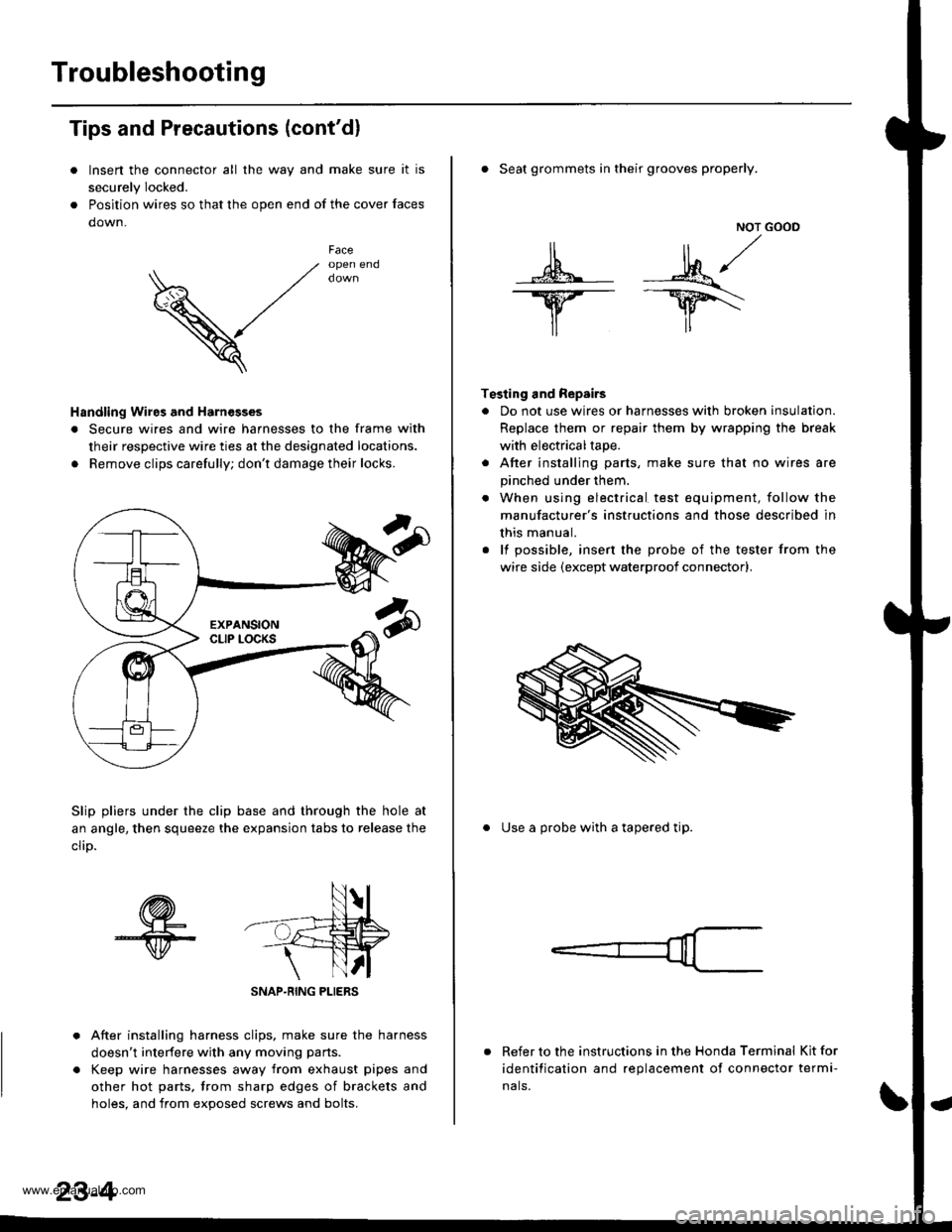
Insen the connector all the way and make sure it is
securely Iocked.
Position wires so that the open end of the cover faces
down.
V
Faceopen end
Handling Wires and Harnesges
. Secure wires and wire harnesses to the frame with
their respective wire ties at the designated locations.
. Remove clips carefully; don't damage their locks.
Slip pliers under the clip base and through the hole at
an angle, then squeeze the expansion tabs to release the
clrD.
After installing harness clips, make sure the harness
doesn't interfere with any moving pans.
Keep wire harnesses away from exhaust pipes and
other hot parts, trom sharp edges of brackets and
holes. and from exoos€d screws and bolts.
NOT GOOD
A -M/
lr lr*
T€sting and Repairs
. Do not use wires or harnesses with broken insulation.
Replace them or repair them by wrapping the break
with electricaltape.
. After installing parts, make sure that no wires are
pinched under them.
. When using electrical test equipment, follow the
manufacturer's instructions and those described in
this manual.
. lf possible, insert the probe of the tester from the
wire side (except waterproof connector).
. Seat grommets in their grooves properly.
. Use a probe with a tapered tip.
Refer to the instructions in the Honda Terminal Kit for
identification and replacement of connector termi-
nals.
www.emanualpro.com
Page 1240 of 1395
Lighting SystemHeadlights
Dafime Running Lights Resistor
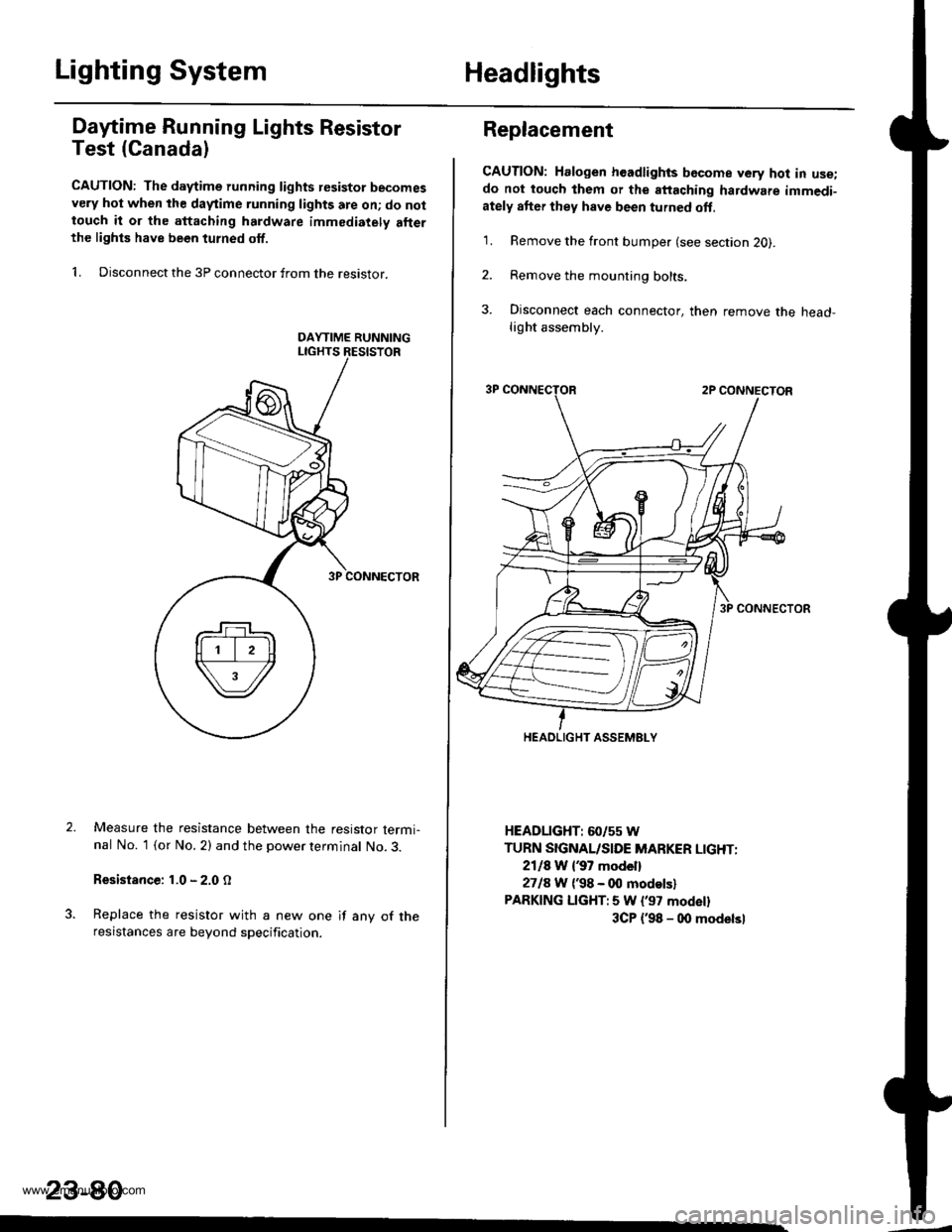
Test (Canada)
CAUTION: The d.ytime running lights resistor becomesvery hot when the daytime running lights are on; do nottouch it or the attaching hardware immediately allerthe lighls have been turned off.
1. Disconnect the 3P connector from the resistor.
Measure the resistance between the resistor termi-nal No. 1 (or No. 2) and the power terminal No. 3.
Resistance: 1.0 - 2.0 O
Replace the resistor with a new one if any of theresistances are beyond specification.
23-80
Replacement
CAUTION: Halogen headlights bGcome very hot in use;do not touch them or the attaching hardware immedi-ately after they have been turned oft.
1. Remove the front bumper (see section 2O).
2. Remove the mounting bolts.
3. Disconnect each connector, then remove the head-light assembly.
HEADLIGHT: 60/55 W
TURN SIGNAL/SIDE MARKER LIGHT:
2118 W {37 model}
2718 W ('98 - 00 modelsl
PARKING LIGHT:5 W l'97 modell
3CP {'98 - 00 modelsl
HEADLIGHT ASSEMELY
www.emanualpro.com
Page 1262 of 1395
Stereo Sound System
Audio Unit Removal
Make sure you have the anti-theft code for the
radio, then write down the frequencies for the
radio's preset buttons (with anti-theft feature).
Remove the center panel (see section 201,
Remove the four mounting bolts, and pull the audio
unit out.
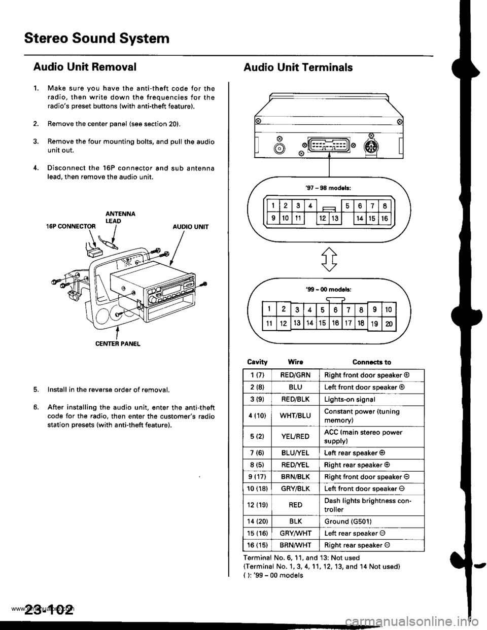
Disconnect the 'l6P connector and sub antenna
lead, then remove the audio unit.
Install in the reverse order of removal.
After installing the audio unit, enter the anti-theft
code for the radio. then enter the customer's radio
station presets (with anti-theft feature).
1.
AUDIO UNIT
CENTEB PANEL
23-102
Audio Unit Terminals
CavrtyWireConnoct3 to
Terminal No.6, 11, and 13: Not used(Terminal No. 1,3, 4,'11,12, 13, and '14 Not us6d)
{ ): '99 - 00 models
1{7)RED/GRNRight front door speaker @
2 {8}BLULeft front door speaker @
3 {9)RED/BLKLights-on signal
4 (10)WHT/BLUConstant power (tuning
memory)
5 (2)YEUREDACC (main sterso power
supplyl
7 (6)BLU/YELLeft rear soeaker @
8 (s)RE D/VELRight rear speaker @
9 (17)BRN/BLKRiqht f.ont door speaker O
10 (18)GRY/BLKLeft front door soeaker O
12 (19)REDDash lights brightness con-
troller
14 (20)BLKGround (G501)
15 (16)GRYMHTLeft rear speaker O
16 (15)BRN^ll/HTRight resr speaker O
www.emanualpro.com
Page 1282 of 1395
Hatch Glass Opener
Solenoid Test
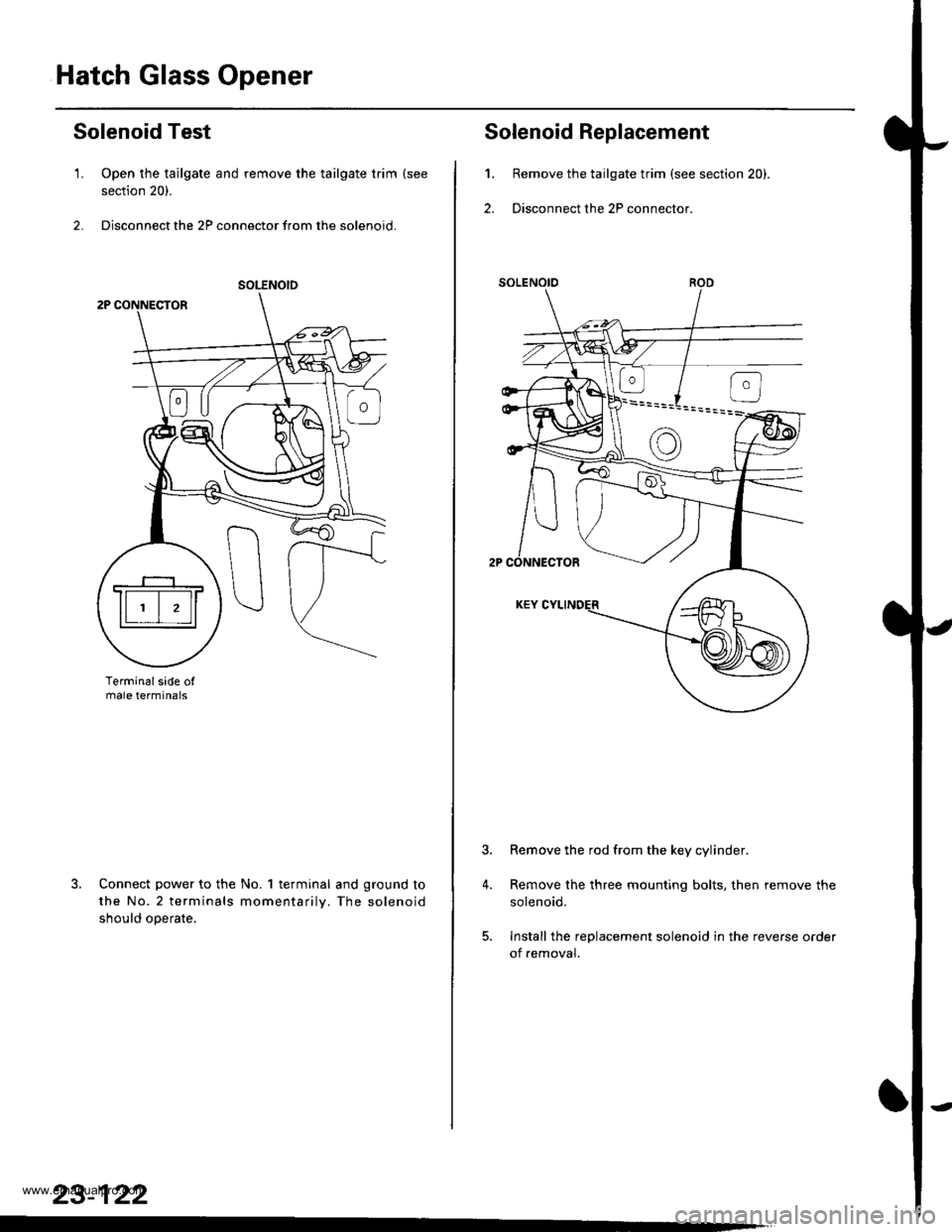
1. Open the tailgate and remove the tailgate trim (see
section 20).
2. Disconnect the 2P connector from the solenoid.
Terminalsade ofmale termtnals
Connect power to the No. 1 terminal and ground to
the No.2 terminals momentarilv. The solenoid
should ooerate.
SOLENOID
23-122
't.
2.
4.
Solenoid Replacement
Remove the tailgate trim (see section 20).
Disconnect the 2P connector.
Remove the rod from the key cylinder.
Remove the three mounting bolts, then remove the
solenoid.
Install the replacement solenoid in the reverse oader
of removal.
www.emanualpro.com
Page 1301 of 1395
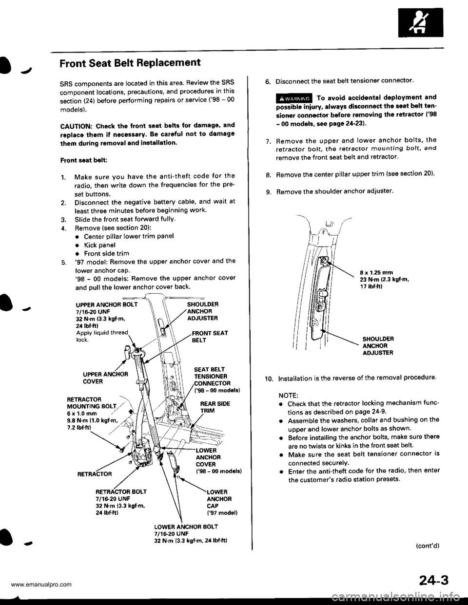
JFront Seat Belt RePlacement
SRS components are located in this area. Review the SRS
component locations, precautions, and procedures in this
section (24) before performing repairs or service ('98 - 00
models).
CAUTION: Check the front seat bslts for damago. and
replaco thom if necessary. Be careful not to damage
them during removal and in3tallation'
Front scat bolt:
1. Make sure you have the anti-theft code for the
radio, then write down the frequencies for the pre-
set buttons.
2. Disconnect the negative battery cable, and wait at
least three minutes before beginning work.
3. Slide the front seat forward fully.
4. Bemove (see section 20):
. Center pillar lower trim Pane
. Kick oanel
. Front side trim
5. '97 model: Remove the upper anchor cover and the
lower anchor caP.'98 - oO models: Remove the upper anchor cover
and pull the lower anchor cover back.
UPPEN ANCHOR BOLT
7/1&20 UNF32 N.m (3.3 kgt'm.24 tbf.ft)
SHOULDERANCHORADJUSTER
Apply liquid threadlock.
9.8 N.m (1.0 kgt.m,?.2 tbtft)
UPPERCOVER
RETRACTORMOUNTING BOLTZ,,Gx1.0mm ./
SEAT BELTTENSIONER
{'98 - 0o modols)
REAR SIDE
ANCHORCOVERl'98 - 00 models)
ANCHORCAP('97 modell
RETRACTOR BOLT7/1&20 UNF32 N.m 13.3 kgt m,24 tbt.ft)
LOWER ANCHOR BOLT?,/1&20 UNF32 N.m {3.3 kgf.m, 2,1 lbf.ftl
o.Disconnect the seat belt tensiongr connector.
@ To avoid accidontal deployment and
possibte inlury, always disconnect the soat bsh ton-
sion€r connoctor bofore rsmoving th6 retractor l'98
- 00 modsls, se€ pa ge 21-231 .
Remove the uDDer and lower anchor boits, the
retractor bolt, the retractor mounting bolt, and
remove the front seat belt and retractor.
Remove the center pillar upper trim (see section 20).
Remove the shoulder anchor adjuster.
7.
9.
8.
I x 1.25 mm23 N.m 12.3 kgt.m,1? tbf.ft)
SHOULDERANCHORADJUSTER
10. lnstallation isthe reverse of the removal procedure.
NOTE:
Check that the retractor locking mechanism func-
tions as described on Page 24-9.
Assemble the washers, collar and bushing on the
uooer and lower anchor bolts as shown.
Eefore installing the anchor bolts, make sure there
are no twists or kinks in the front seat belt.
Make sure the seat belt tensioner connector ls
connected securelv.
Enter the anti-theft code for the radio, then enter
the customer's radio station presets
(cont'd)
24-3
www.emanualpro.com
Page 1302 of 1395
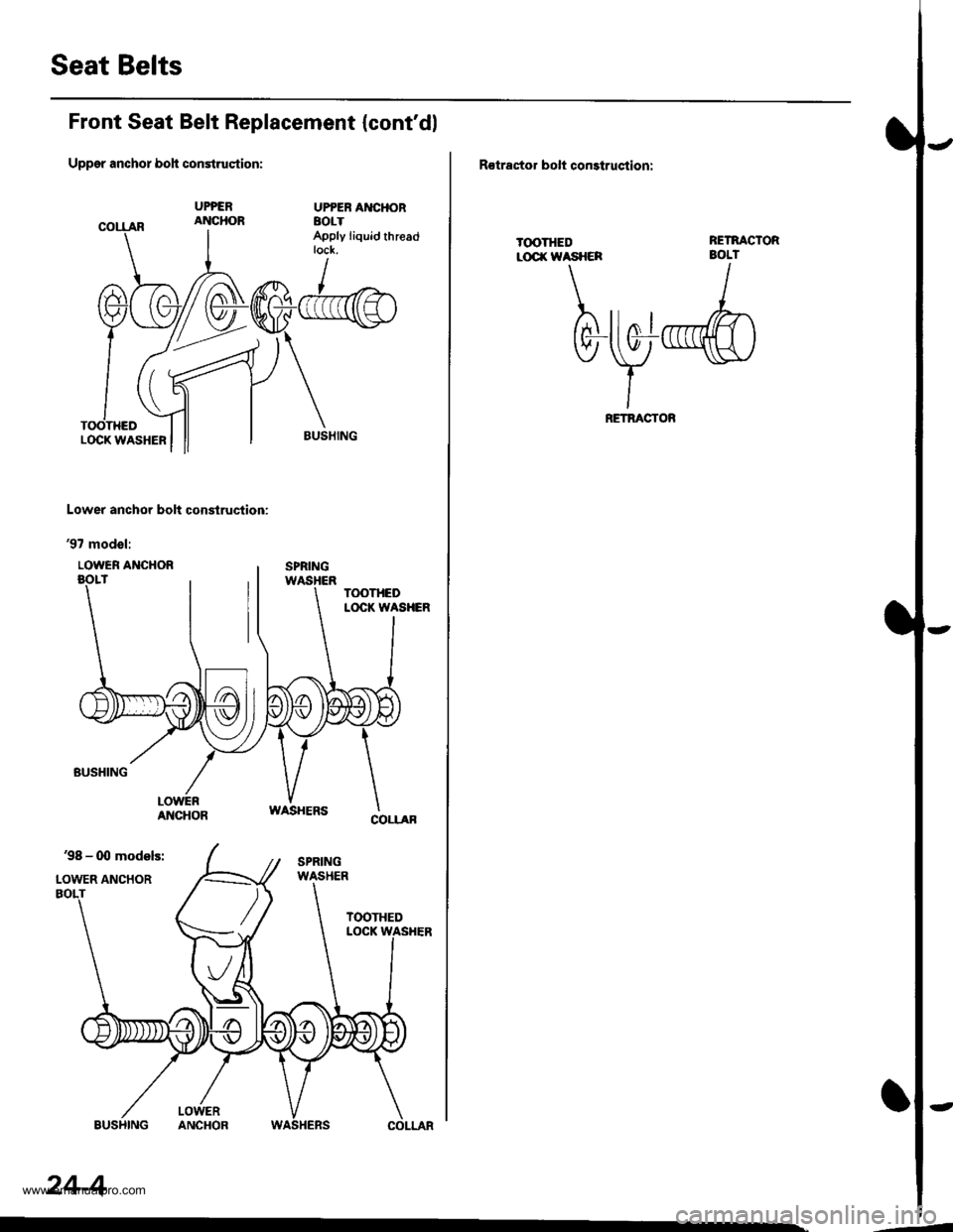
Seat Belts
Front Seat Belt Replacement {cont'dl
Uppgr anchor boh construqtion:
UPPEB AI{CHORaolTApply liquid threadtock.
Lower anchor bolt construction:
'97 modol:
LOWER ANCHOR
24-4
,--
R€tractor bolt construqtion:
T(X)THEDLOCI( WASHCR
RETNACTORBOLT
bwd
RETBACTOR
www.emanualpro.com
Page 1303 of 1395
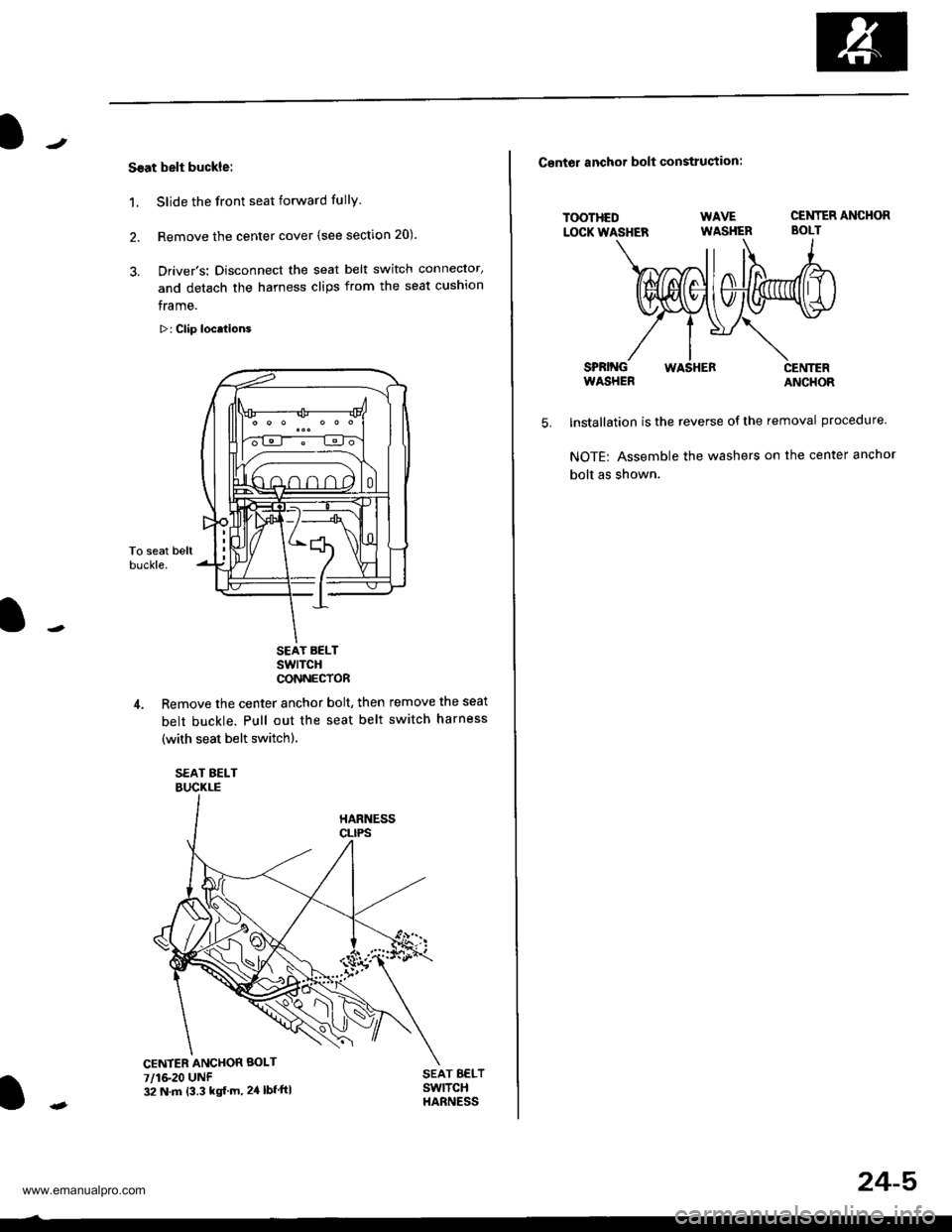
Ssat belt buckle:
1. Slide the front seat forward fully
2. Remove the center cover (see section 20).
3. Driver's: Disconnect the seat belt switch connector,
and detach the harness clips from the seat cushion
frame.
>: Clip locations
To seat beltbuckle.
SEAT BELTswlTcHCONNECTOR
4. Remove the center anchor bolt, then remove the seat
belt buckle. Pull out the seat belt switch harness
(with seat belt switchl.
SEAT BELTBUCKLE
SEAT B€LTSwlTCHHARNESS
CENTER ANCHOR BOLT
7/1&20 UNF32 N.m {3.3 kg{ m, 24 lbf ftl
24-5
Csntor anchor bolt construstion:
TOOTHEDLOCK WASHER
SPRINGWASHERWASHERCENTERANCHOR
WAVE CENTER ANCHOR
WASHER BOLT
5.lnstallation is the reverse of the removal procedure.
NOTE: Assemble the washers on the center anchor
bolt as shown.
www.emanualpro.com
Page 1304 of 1395
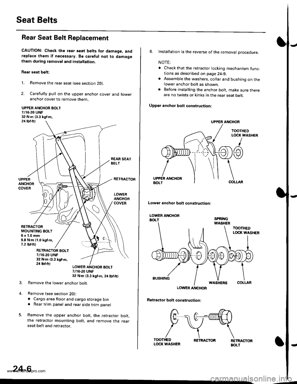
Seat Belts
Rear Seat Belt Replacement
CAUTION: Check the rear s€at belts for damage, andreplace lhem if necessa.y. Be caretul not to damagethem during temoval and installation.
Rear seat belt:
1, Remove the rear seat {see section 20}.
2. Carefully pull on the upper anchor cover and loweranchor cover to remove them.
UPPER ANCHOR BOLT7/16-20 UNF32 N.m 13.3 kg{.m,24 tbt.ft)
REAR SEATBELT
RETRACTOBMOUNTING BOLT6x1.0mm9.8 N.m (1.0 kgt.m.7.2 rbf.ftl
UPPERANCHORCOVER
RETRACTOR
LOWERANCHORCOVER
RETRACIOR EOLT7/16-20 UNF32 N.m {3,3 kgf.m,24 rbr.ft)
3.
4.
LOWER ANCHOF BOLT7/1S20 UNF32 N.m 13.3 kgl.m, 2/r lbf.ftl
Remove the lower anchor bolt.
Remove (see section 20):. Cargo area floor and cargo storage bin. Rear trim panel and rear side trim panel
Remove the upper anchor bolt, the retractor bolt.the retractor mounting bolt, and remove the rearseat belt and retractor.
24-6
,--
6. Installation is the reverse of the removal procedure.
NOTE:
. Check that the retractor locking mechanism func-tions as described on page 24-9.. Assemble the washers, collar and bushing on thelower anchor bolt as shown.. Before installing the anchor bolt, make sure thereare no twists or kinks in the rear seat belt.
Upper anchot bolt construction:
UPPER ANCHOR
TOOTHEOLOCK WASHER
/
A t
ANCHORCOLLAF
Lowel anchor bolt construqtion:
LOWER ANCHORBOLTSPRINGWASHEB
TOOTHEDLOCI( WASHER
BUSHINGWASHERSCOLLAR
LOWER ANCHOR
Rgtractor boll construction:
RETMCTORBOLT
/ r>--->.
f/F\-. (t--nnnllH \
P \v*\
/\\T(X)THEDLOCK WASHERRETRACTOR
www.emanualpro.com
Page 1305 of 1395
)J
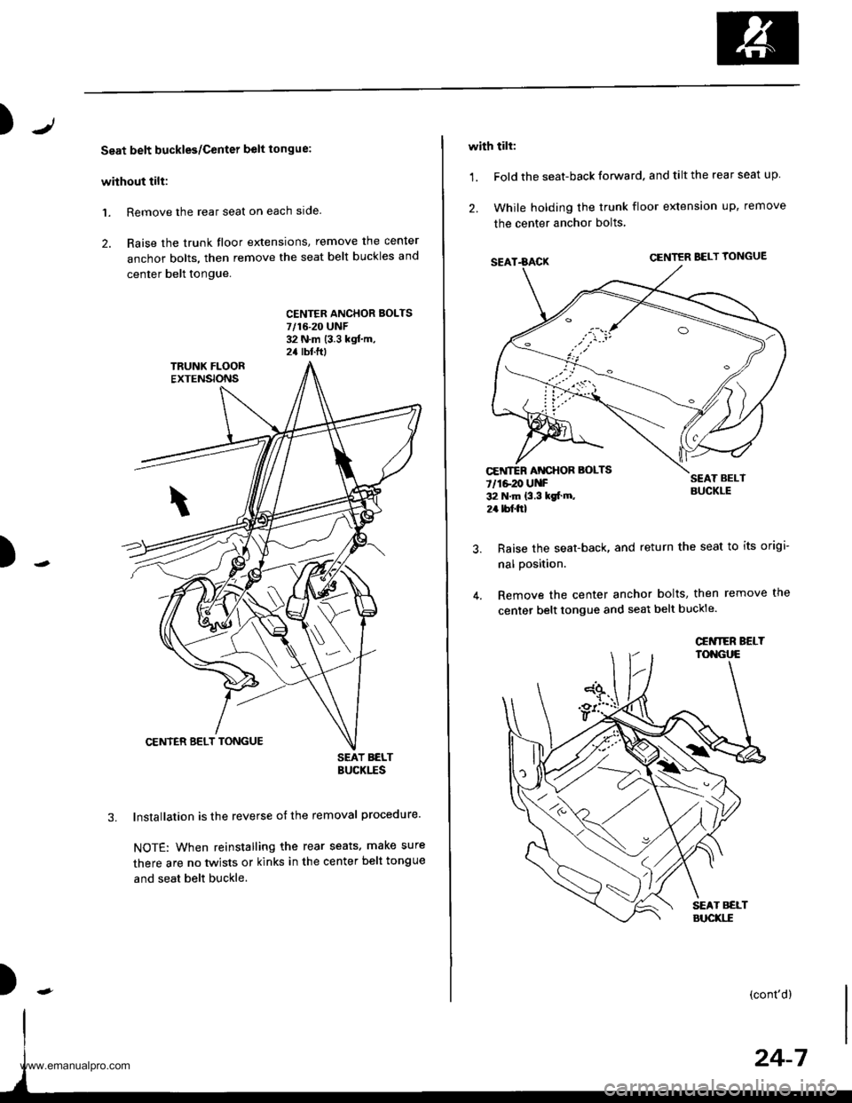
Seat belt buckles/Center belt tongue:
without tilt:
1. Remove the rear seat on each slde.
2. Raise the trunk floor extensions, remove the cenler
anchor bolts, then remove the seat belt buckles and
center belt tongue.
CENTFR ANCHOR BOLTS7/16-20 UNF32 N.m (3.3 kgf.m,2a rbtftt
)
SEAT BELTBUCKITS
lnstallation is the reverse of the removal procedure.
NOTE: When reinstalling the rear seats. make sure
there are no twists or kinks in the center belt tongue
and seat belt buckle.
)
with tilt:
1. Fold the seat-back forward. and tilt the rear seat up
2. While holding the trunk floor extension up, remove
the center anchor bolts
SEAT.BACKCENTER BELT YONGUE
SEAT BELTBUCKLE
Raise the seat-back, and return the seat to its origi-
nal position.
Remove the center anchor bolts, then remove the
center belt tongue and seat belt buckle.
CEiITER AT{CHOR BOLTS
7/1e20 UNF32 N.m {3.3 kgt m,
2r bf.frl
\\
(cont'd)
www.emanualpro.com
Page 1306 of 1395
Seat Belts
Rear Seat Belt Replacement (cont'dl
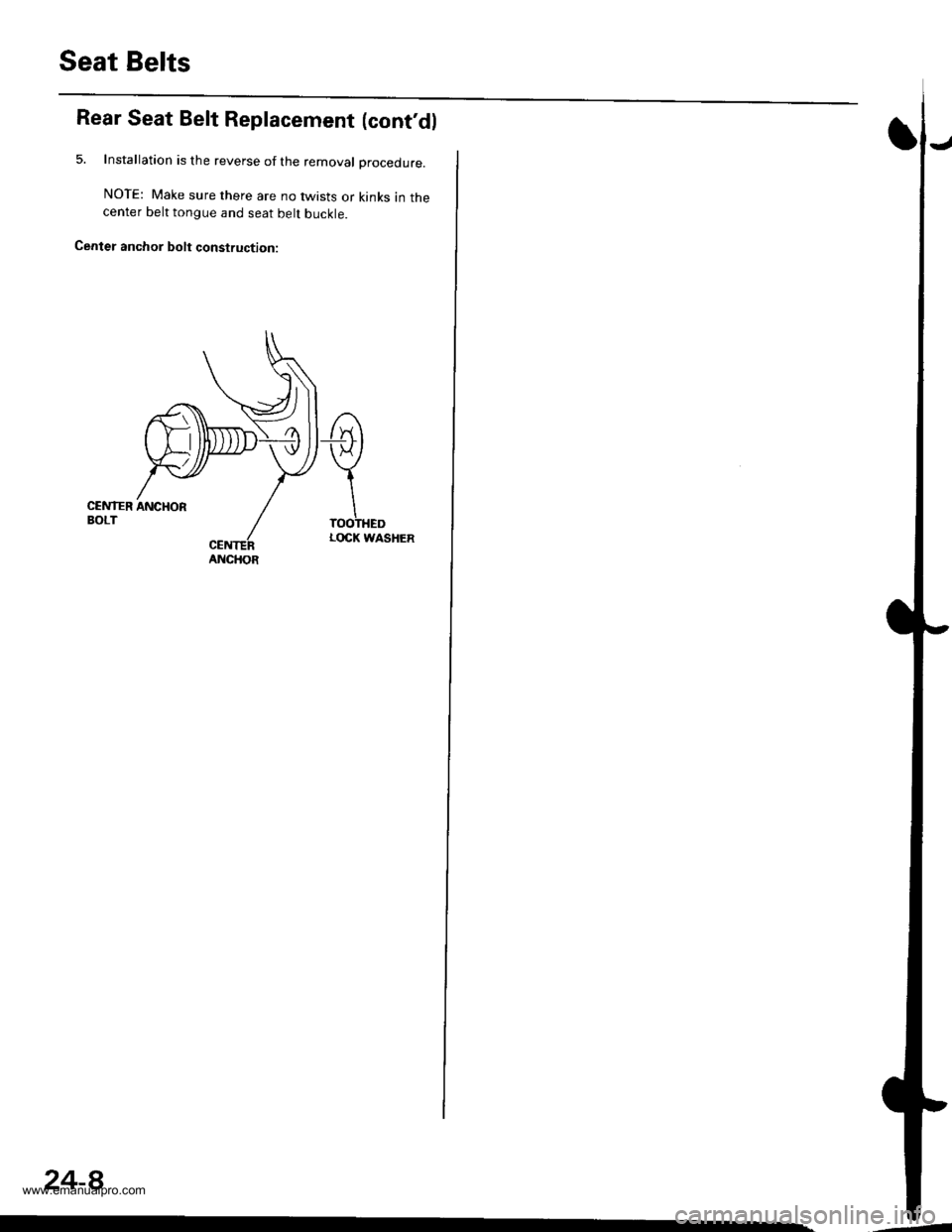
5. Installation is the reverse of the removal Drocedure.
NOTE: Make sure there are no twists or kinks in thecenter belt tongue and seat belt buckle.
Cenler anchor bolt construction:
€
\TOOTHEDLOCK WASHER
ANCHOR
24-8
,-4
www.emanualpro.com