Adiustment HONDA CR-V 1999 RD1-RD3 / 1.G Owner's Manual
[x] Cancel search | Manufacturer: HONDA, Model Year: 1999, Model line: CR-V, Model: HONDA CR-V 1999 RD1-RD3 / 1.GPages: 1395, PDF Size: 35.62 MB
Page 926 of 1395
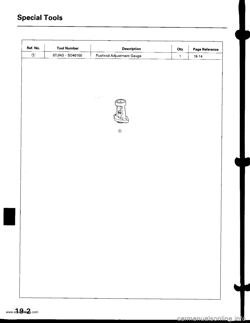
Special Tools
Ref. No. Tool Number Description ety psge Reference
(, | 07JAG. SD40100 | Pushrod Adiustment cauge I r I tg_rt
19-2
www.emanualpro.com
Page 929 of 1395
Brake Pedal
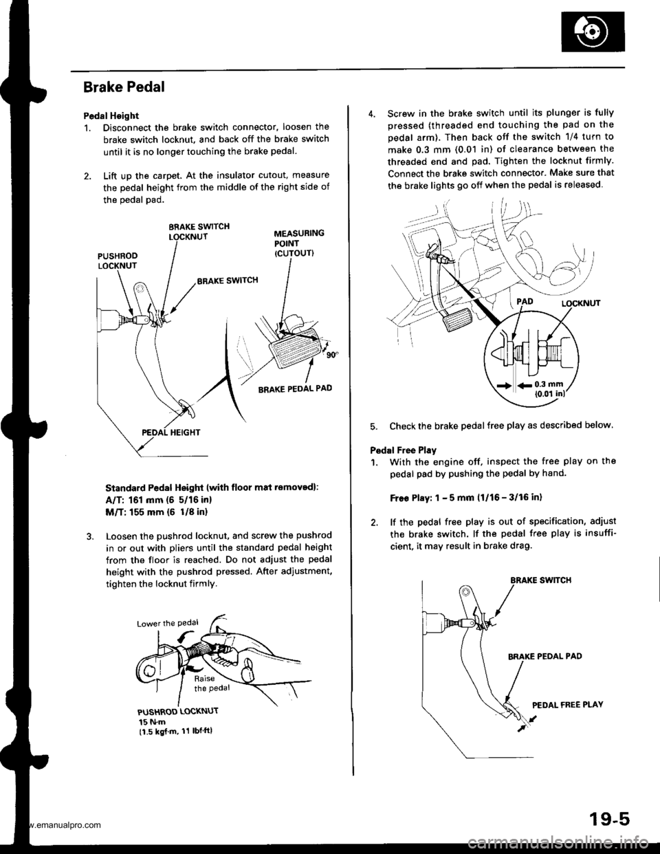
Pedal Hoight
1. Disconnect the brake switch connector, loosen the
brake switch locknut, and back off the brake switch
until it is no longer touching the brake pedal.
2. Lift up the carpet, At the insulator cutout, measure
the pedal height from the middle of the right side of
the oedal pad.
BRAKE SWITCH
ERAKE SWITCH
Standard Pedal Height (with floor m8i removed):
A/T: 161 mm (5 5/16 in)
M/T: 155 mm {6 U8 in}
Loosen the pushrod locknut, and screw the pushrod
in or out with pliers until the standard pedal height
from the floor is reached. Do not adjust the pedal
height with the pushrod pressed. After adiustment,
tighten the locknut firmly.
PUSHROD LOCKNUT
15 N.m11.5 kgj m, 11 lbf ftl
4. Screw in the brake switch until its plunger is fully
pressed (threaded end touching the pad on the
pedal arm), Then back otf the switch 1/4 turn to
make 0.3 mm (0.01 in) of clearance between the
threaded end and pad. Tighten the locknut firmly.
Connect the brake switch connecto.. Make sure that
the brake lights 90 off when the pedal is released
5. Checkthe brake pedalfree play as described below
Pedal Free Play
1. With the engine off. inspect the free play on the
pedal pad by pushing the pedal by hand-
Free Play: 1 - 5 mm (1/16 - 3/16 in)
2. lf the pedal free play is out of specification, adiust
the brake switch. lf the pedal free play is insuffi-
cient, it may result in brake drag.
swtTcH
PEOAL PAD
PEDAL FREE PLAY
19-5
www.emanualpro.com
Page 930 of 1395
Inspection and Adjustment
Parking Brake
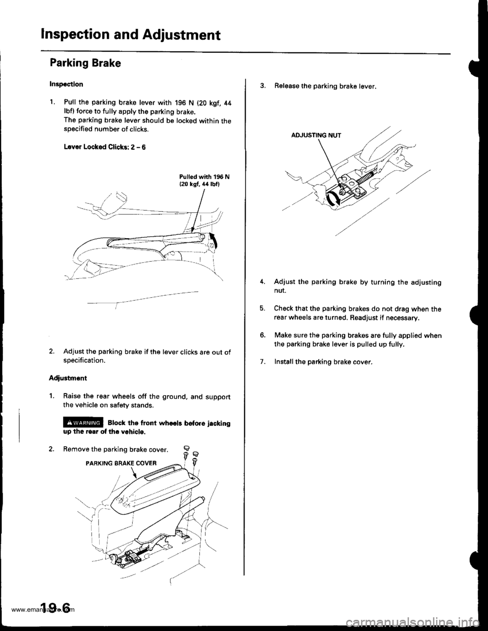
Inspeqtion
1. Pull the parking brake lever with
lbfl force to fully apply the parking
The parking brake lever should be
specified number of clicks.
L.var Lockod Clicks: 2 - 6
196 N (20 kqf, 44
brake.
locked within the
2. Adjust the parking brake if the lever clicks are out ofspecification.
Adiustment
1. Raise the rear wheels off the ground. and support
the vehicle on safety stands.
@@ Bbck tho front who€ts betore iackingup the rear ot tho vohicle.
2. Remove the parking brake cover
PARKING BRAKE COVER
19-6
3. Release the parking brake lever.
Adjust the parking brake by turning the adjusting
nut.
Check that the parking brakes do not drag when therear wheels are turned. Readjust if necessary.
Make sure the parking brakes are fully applied when
the parking brake lever is pulled up fully.
Installthe parking brake cover.7.
www.emanualpro.com
Page 982 of 1395
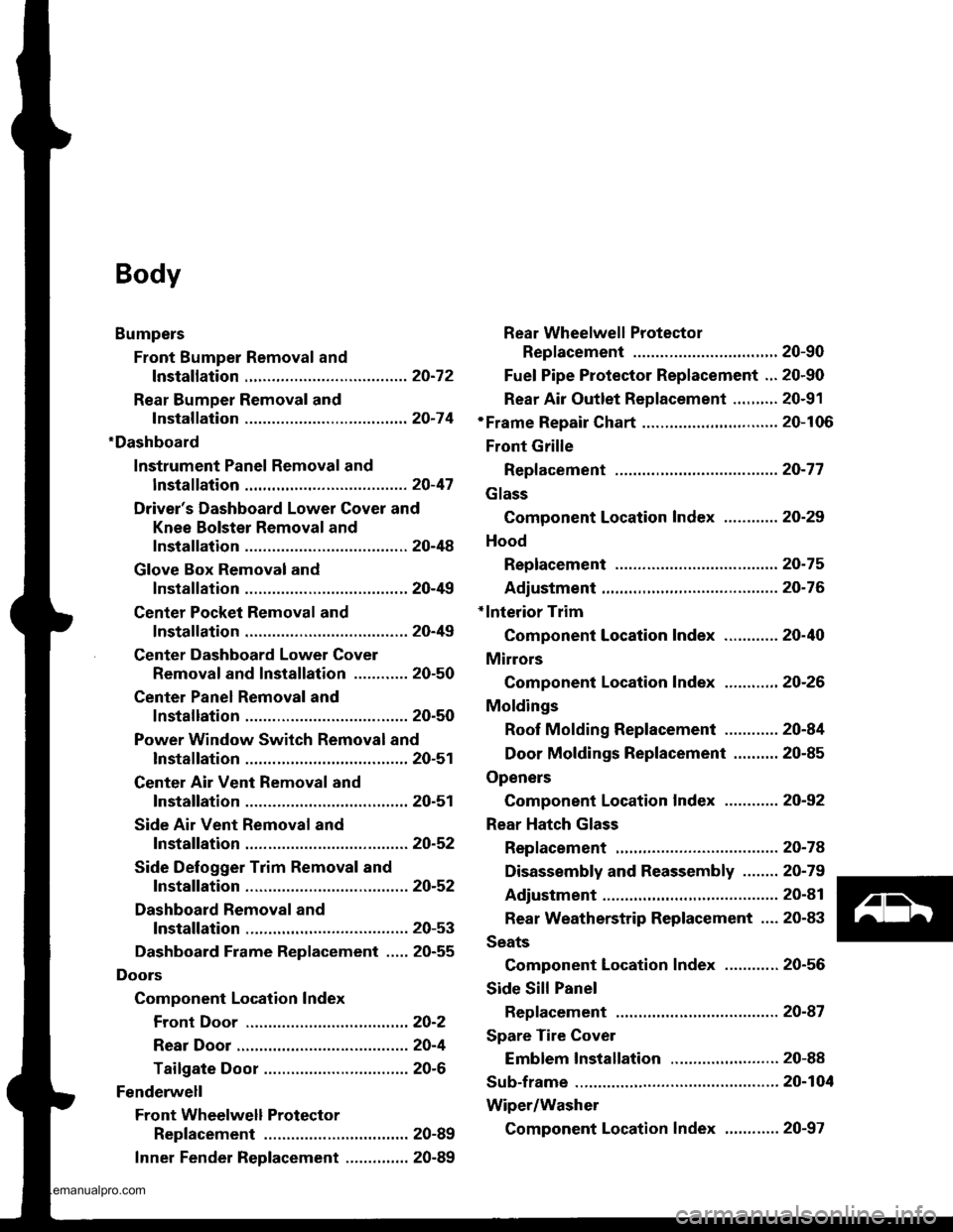
Body
Bumpers
Front Bumper Removal and
fnstaflation .........20-72
Rear Bumper Removal and
fnstaflation .........20-74
'Dashboard
lnstrument Panel Removal and
lnstallation .........20-47
Driver's Dashboard Lower Cover and
Knee Bolster Removal and
Installation .........20-48
Glove Box Removal and
lnstallation .........20-49
Center Pocket Removal and
lnstallation .........20-49
Center Dashboard Lower Cover
Removal and lnstallation ............ 20-50
Center Panel Removal and
lnstallation .........20-50
Power Window Switch Removal and
lnstallation .........20-51
Center Air Vent Removal and
lnstallation .........20-51
Side Air Vent Removal and
fnstallation .........20-52
Side Defogger Trim Removal and
fnstallation .........20-52
Dashboard Removal and
lnstallation .........20-53
Dashboard Frame Replacement ..... 20-55
Doors
Component Location Index
Front Door ,,...,,,,20-2
Rear Door ...........20-4
Tailgate Door ................................ 20-6
Fenderwell
Front Wheelwell Protector
Replacement .....20-89
Inner Fender Replacement .,.....,.,.... 20-89
Rear Wheelwell Protectol
Replacement .....20-90
Fuel Pipe Protector Replacement ... 20-90
Rear Air Outlet Replacement .......... 20-91
*Frame Repair Chart .............................. 20-106
Front Grille
Repf acement .........20-77
Glass
Component Location Index ............ 20-29
Hood
Replacement ......,,,20-75
Adjustment ............20-76
*lnterior Trim
Component Location Index ............ 20-40
Mirrors
Component Location Index .........,,, 20-26
Moldings
Roof Molding Replacement ............ 20-84
Door Moldings Replacement .......... 20-85
Openers
Component Location Index ............ 20-92
Rear Hatch Glass
Replacement .........20-74
Disassembly and Reassembly ........ 20-79
Adiustment ............20-81
Rear Weatherstrip Replacement .... 20-83
Seats
Component Location Index ............ 20-56
Side Sill Panel
Repfacement .........20-87
Spare Tire Cover
Emblem Installation ........................ 20-88
Sub-frame ..................20-104
Wiper/Washer
Component Location lndex ,,,,,....... 20-97
www.emanualpro.com
Page 985 of 1395
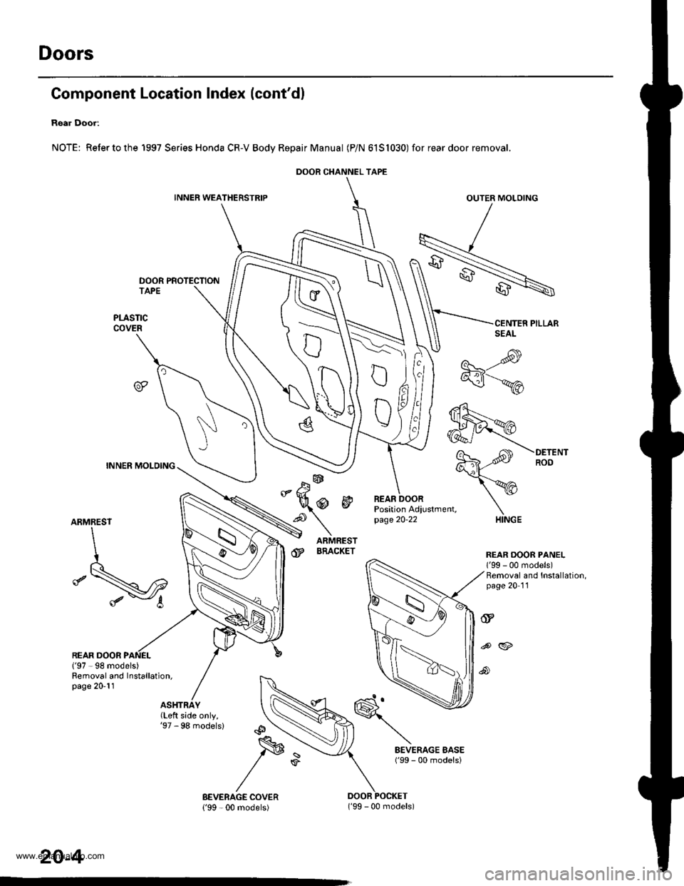
Doors
Gomponent Location Index (cont'dl
Rear Door:
NOTE: Refertothe 1997 Series Honda CR-V Bodv RepairManual (P/N 6151030) for rear door removal.
INNER WEATHERSTRIPOUTER MOLOING
DOOR PROTECTION
ARMREST
REAR DOOR('97 -98 models)
HINGE
REAR DOOR PANEL1'99 - 00 models)Removal and Installation,page 20 '11
@
ARMRESTBRACKET
Position Adiustment,page 20-22
tu4
dP
@
o
@
Bemoval and Installation,page 20-11
(Left side only,'97 - 98 models)
\
DOOR CHANNEL TAPE
FR,
)Ei
D\
\a
20-4
('99 - 00 models)
www.emanualpro.com
Page 987 of 1395
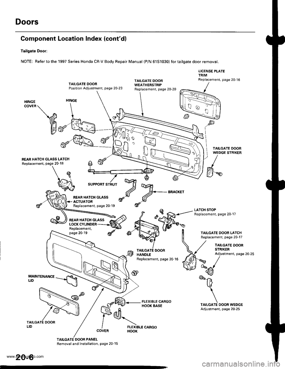
Doors
Component
Tailgate Door:
NOTE: Refer to the
Location Index (cont'dl
1997 Series Honda CR-V Body Repair Manual {P/N 61S1030) for tailgate door removal.
LICENSE PLATETRIMReplacement, page 20-16TAILGATE OOORPosition Adjustment, page 20-23
TAILGATE DOORWEATHERSTRIP
HINGECOVER \
V
illt
REAR HATCH GLASS LATCHReplacement, page 20 18
HINGE
\
I
SUPPORT STRUT
€\A
LATCH STOPReplacement, page 20-17
Replacement,page 20'19
TAILGATE DOOR PANELRemoval and Installation, page 20-15
TAILGATE DOOR LATCHReplacement, page 20-17
TAILGATE DOORHANDLEReplacement, page 20-16
TAILGATE DOORSTRIKERAdjustment, page 20-25
k@/
%
-6
\
TAILGATE DOOR WEDGEAdiustment, page 20-25
N
REAR HATCH GLASSACTUATORReplacement, page 20-19
REAR HATCH GLASS
lVr
d+-BA^cKEr
d
d\
FLEXIBLE CARGOHOOK
20-6
www.emanualpro.com
Page 1003 of 1395
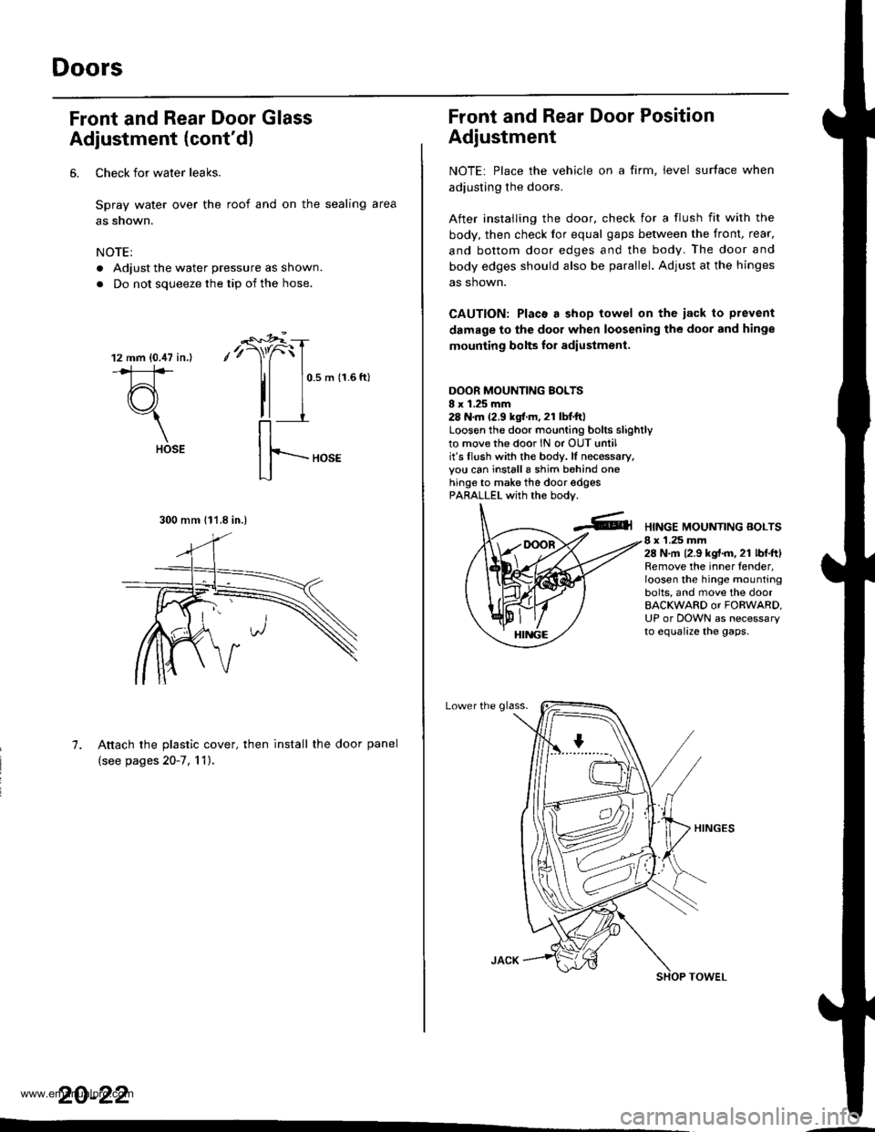
Doors
Front and Rear Door Glass
Adiustment (cont'dl
6. Check for water leaks.
Spray water over the roof and on the sealing area
as snown.
NOTE:
. Adjust the water pressure as shown.
. Do not soueeze the tio of the hose.
12 mm {0.47 in.l
#
(r\"1
HOSE
-"'*r"i
,'r)"f
tl
0.5 m (1.6 ftl
7. Attach the plastic cover, then install the door panel
(see pages 20-7, 'l 1),
20-22
..-
300 mm 111.8 in.)
Front and Rear Door Position
Adjustment
NOTE: Place the vehicle on a firm, level surface when
adiusting the doors.
After instailing the door, check for a flush fit with the
body, then check lor equal gaps between the front, rear.
and bottom door edges and the body. The door and
body edges should also be parallel. Adjust at the hinges
as shown.
CAUTION: Placa a shop towel on the iack to prevent
damage to the door when loosening the door and hinge
mounting bolts lor adiustment.
DOOR MOUNTING BOLTSI x 1.25 mm28 N.m 12.9 kgtr.m, 21 lbI.ftlLoosen the door mounting bolrs slighrlyto movethe door lN or OUT untilit's flush with the bodv. lf necessary,you can installa shim behind onehinge to make the door edgesPARALLEL with the bodv.
HINGE MOUNTING BOLTS8 x 1.25 mm28 N,m 12.9 kgt.m. 21 lbl.ftlRemove the inner fender,loosen the hinge mountingbolts, and move the doorBACKWARD or FORWARD,UP or DOWN as necessaryto equalize the gaps.
Lower the glass.
www.emanualpro.com
Page 1004 of 1395
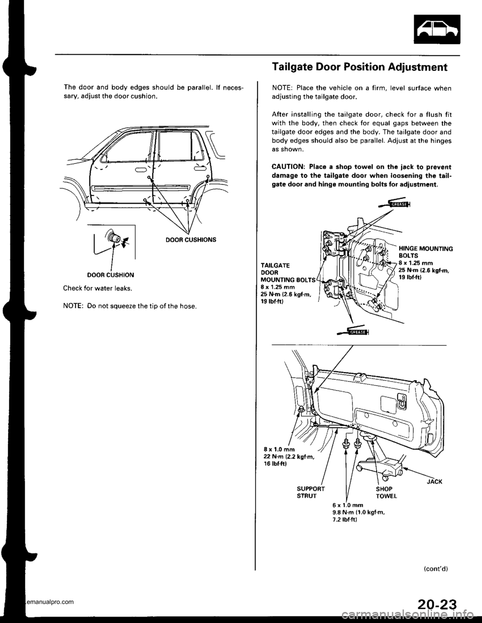
The door and body edges should be parallel. lf neces-
sary, adjust the door cushion.
ry.DOOR CUSHION
Check for water leaks.
NOTE: Do not squeeze the tip ofthe hose.
oooR cusHroNs
Tailgate Door Position Adjustment
NOTE: Place the vehicle on a firm, level surface when
adjusting the tailgate door.
After installing the tailgate door. check for a flush fit
with the body, then check for equal gaps between the
tailgate door edges and the body. The tailgate door and
body edges should also be parallel. Adjust at the hinges
as snown.
CAUTION: Place a shop towel on the iack lo prevent
damage to the tailgale door when loos€ning the tail-
gate door and hinge mounting bolts for adiustment.
TAILGATEDOORMOUNTING sOLTS8 x 1.25 mm25 N.m {2.6 kgf.m,19 tbf.ft)
HINGE MOUNYINGBOLTS8 x 1.25 mm25 N.m 12.6 kgt m,19 rbf.ftl
8x1.0mm22 N'rrl� 12.2 kgl.m,16 tbt.ftl
6xl.0mm9.8 N.m {1.0 kgt m,1.2 tbl.ltl
(cont'd)
20-23
www.emanualpro.com
Page 1005 of 1395
Doors
(cont'd)
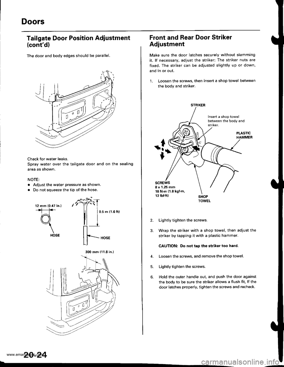
The door and body edges should be parallel.
Check for water leaks.
Spray water over the tailgate door and on the sealing
area as shown.
NOTE:
. Adjust the water pressure as shown.
. Do not squeeze the tip ofthe hose.
Tailgate Door Position Adiustment
-€*4
,'r)"C
II
0.5 m {1.6 ft}
20-24
l2 mm (0.47 in.).*1:]*
d3"1
HOSE
300 mm {11.8 in.l
Front and Rear Door Striker
Adjustment
Make sure the door latches securely without slamming
it, lf necessary, adjust the striker: The striker nuts are
fixed. The striker can be adjusted slightly up or down,
and in or out.
1. Loosen the screws, then insert a shop towel between
the body and striker.
Insert a shop towelbetween the body and
scREws8 x 1 .25 mm18 N.m (1.8 kgt.m,13 rbf.ft)
2.
J.
Lightly tighten the screws.
Wrap the striker with a shop towel, then adjust the
striker by tapping it with a plastic hammer.
CAUTION: Do not tap the striksr loo hard.
Loosen the screws. and remove the shop towel.
Lightly tighten the screws.
Hold the outer handle out, and push the door against
the body to be sure the striker allows a flush fit, lf the
door latches properly. tighten the screws and recheck.
4.
5.
6.
STRIKER
www.emanualpro.com
Page 1039 of 1395
Seats
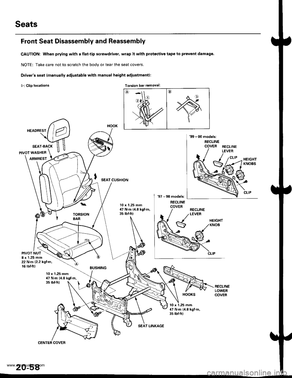
Front Seat Disassembly and Reassembly
CAUTION: When prying with a flat-tip screwdriver, wrap it with protsqtive tape to prevent damage.
NOTE: Take care not to scratch the bodv or tear the seat covers.
Driver's seat lmanually adiustable with manual height adiustmentl:
>: Clio locations Torsion bar removal:Torsion bar removal:
SEAT CUSHION
10 x 1.25 mm,17 N.m (,1.8 kgt m,35 tbt.ft)
PIVOT NUT8 x 1.25 mm22 N.n 12.2 kgl.m,16 rbI.ft)
10 x 1.25 mm47 N.m (4.8 kgf.m,35 tbtfr)
10 x 1 .25 mm47 N.m {,1.8 kgl.m.35 rbt.ft)
20-58
HOOK
HOOKS
www.emanualpro.com