Floor HONDA CR-V 1999 RD1-RD3 / 1.G Owner's Manual
[x] Cancel search | Manufacturer: HONDA, Model Year: 1999, Model line: CR-V, Model: HONDA CR-V 1999 RD1-RD3 / 1.GPages: 1395, PDF Size: 35.62 MB
Page 1016 of 1395
22.
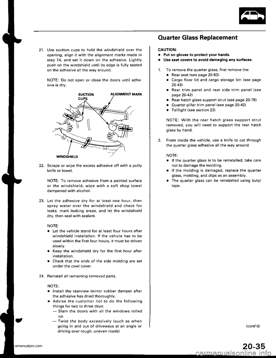
21. Use suction cups to hold the windshield over the
opening, align it with the alignment marks made in
step 14, and set it down on the adhesive. Ljghtly
push on the windshield until its edge is fully seated
on the adhesive all the way around.
NOTEr Do not open or close the doors until adhe-
sive is dry.
SUCTTON ALIGNMENT MARK
Scrape or wipe the excess adhesive off with a putty
knife or towel.
NOTE: To remove adhesive from a painted surface
or the windshield, wipe with a soft shop towel
dampened with alcohol.
Let the adhesive dry for at least one hour, then
spray water over the windshield and check for
leaks. mark leaking areas, and let the windshield
dry, then seal with sealant.
NOTE:
. Let the vehicle stand for at least four hours after
windshield installation. lf the vehicle has to be
used within the first four hours, it must be driven
. Keep the windshield dry for the first hour after
installation.
. Check that the ends of the side molding are set
under the cowl cover.
Reinstall all remaining removed parts.
NOTE:
. Install the rearview mirror rubber damper after
the adhesive has dried thoroughl,.
. Advise the customer not to do the following
things for two to three days:- Slam the doors with all the windows rolled
up.- Twist the body excess,vely {such as when
going in and out of driveways at an angle or
driving over rough. uneven roads).
24.
Ouarter Glass Replacement
CAUTION:
. Put on gloves to prot€ct your hands.
. Use seat covers to avoid damaging any surfaces.
1. To remove the quarter glass, first remove the:
. Rear seat (see page 20-63)
. Cargo floor lid and cargo storage bin (see page
20 431
. Rear trim panel and rear side trim panel (see
page 20-421
. Rear hatch glass support strut (see page 20-78)
. Ouarter pillar trim panel (see page20-421
. Taillight (see section 23)
NOTE: With the rear hatch glass support strut
removed, you will need to support the rear hatch
glass by hand.
2. From inside the vehicle, use a knife to cut through
the quarter glass adhesive all the way around.
NOTE:
. lf the quaner glass is to be reinstalled, take care
not to damage the molding.
. lf the molding is damaged. replace the quarter
glass, molding, and clips as an assembly.
. The quarter glass can be reinstalled using butyl
tape.
(cont'd)
20-35
www.emanualpro.com
Page 1021 of 1395
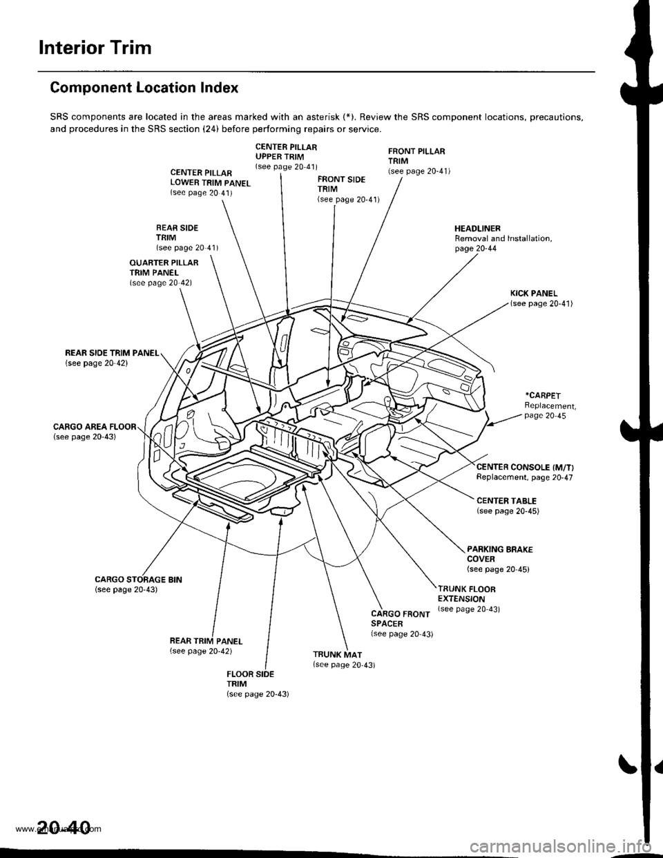
lnterior Trim
20-40
CARGO FRONTSPACER(see page 20 43)
FRONT PILLARTRIM(see page 20-41)
TRUNK FLOOREXTENSION(see page 20 43)
HEADLINERRemoval and lnstallation,page 20-44
Component Location Index
SRS components are located in the areas marked with an asterisk (*). Review the SRS component locations, precautions,
and procedures in the SRS section (24) before performing repairs or service.
CENTER PILLARUPPER TRIM(see page 20 41)CENTER PILLARLOWER TRIM PANEL(see page 20 41)
FRONT SIDETRIM(see page 20-41)
BEAR SIDETEIM(see page 20'41)
OUARTER PILLARTRIM PANEL(see page 20 42)
*CARPET
Replacement,page 20 45
CENTER CONSOLE IM/T}Replacement, page 20-47
CENTEN TABLE(see page 20-45)
PARKING BRAKECOVER(see page 20-45)
TRIM
www.emanualpro.com
Page 1023 of 1395
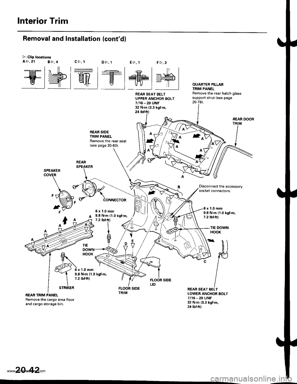
Interior Trim
@wt we@M
REAR SIOETRIM PANELRemove the reat seat(see page 20-63).
FCONNECTOR
2
OUARTER PILLARTNIM PANELRemove the rear hatch glasssupport strut (see page20-741.
Removal and Installation (cont'd)
>i Clip loc.tionsa>,21B>,4c>, 1E>. !F >,3D>, 1
Disconnect the accessorysocket connectors,
9.8 N.m (1.0 kgf.m,1.2lbt-lrl
5x1.0mm6x1.0mm9.8 N.m (1.0 kgtm,7.2 tbf ftl
TIE DOWNHOOK
6x1.0mm
TIEoowNHOOK
v
O\A
D
REAR SEAT BELTLOWER ANCHOR EOLT7/16 - 20 UNF32 N.m {3.3 kgt.m,24 tbl.frl
9.8 N.m (1.0 kgt m,7.2 tbf.ft)
REAR TRIM PANELRemove the cargo area floorand cargo slorage bin.
20-42
REAN SEAT BELTUPPER ANCHOR BOLT7/16-20 UNF32 N.m {3.3 kgt.m,24 rbt.ft)
REAR DOOR
REAR
ffi
STRIKER
www.emanualpro.com
Page 1024 of 1395
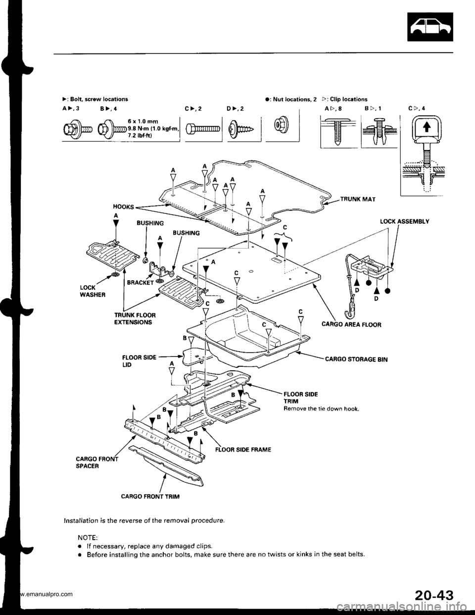
>: Bolt, screw locations
a>,3 B>,4
o: Nut locations, 2 >: Clip locations
TRUNK MAT
CARGO STORAGE BIN
/ rr. 6xl.Omm I
m)b D lbe.8 Nm r1.o ksnm.l-
c>,2 0>,2 A>,8 B>,r
| .€ | r- -I At I tl1|r' t I l���'---llH- | E
GlrrIIITTpl 0pE l w I l--Tr@HPv | | v I vv
LOCK ASSEMBLY
TRUNK FLOOREXTENSIONS
FLOOR SrO€LID
FLOOR SIDE FRAME
CARGO FRONT TRIM
Insta,lation is the reverse of the removal procedure.
NOTE:
. lf necessary, replace any damaged clips.
r Before installing the anchor bolts, make sure there are no twists or kinks in the seat belts.
BUSHING
l^IV
>ilv '%L
"ro"*i*
CARGO AREA FLOOR
l*,hl
20-43
www.emanualpro.com
Page 1025 of 1395
lnterior Trim
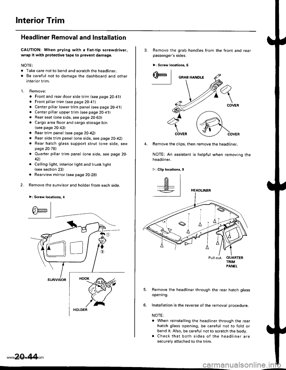
Headliner Removal and Installation
CAUTION: When prying with a tlat-tip screwdriver,
wrap it with protective tape to prevent damage.
NOTE:
. Take care not to bend and scratch the headliner.o Be careful not to damage the dashboard and other
interior trim.
1. Remove:
. Front and rear door side trim (see page 20-41). Front pillartrim (see page 20-41)
. Center pillar lower trim panel (see page 20-41). Center pillar upper trim (see page 20 41). Rear seat (one side, see page 20-63). Cargo area floor and cargo storage bin
{see page 20-43)
. Rear trim panel (see page 20-421
. Rear side trim panel (oneside, see page 20-42l,
. Rear hatch glass support strut (one side, seepage 20-78)
. Ouaner pillar trim panel {one side, see page 20-
42)
. Ceiling light, interior light and trunk light(see section 23)
. Rearview mirror (see page 20-28)
2. Remove the sunvisor and holder from each side.
>: Scaew location3, 4
I
A\"r- |Yr* || -
suNvtsoR
20-44
3. Remove the grab handles from
passenger's sides.
>r Screw locations, 6
the front and rear
ry_l
COVER
4. Remove the clips, then remove the headliner.
NOTE: An assistant is helpful when removing the
headliner.
>: Clip locations,9
HEADLINER
Pullout. OUARTERTRIMPANEL
5. Remove the headliner through the rear hatch glass
openrng.
6. Installation is the reverse of the removal procedure.
NOTE:
. When reinstalling the headliner through the rear
hatch glass opening, be careful not to fold or
bend it, Also, be careful not to scratch the body.. Check that both sides of the headliner are
securely attached to the trim.
www.emanualpro.com
Page 1075 of 1395
Openers
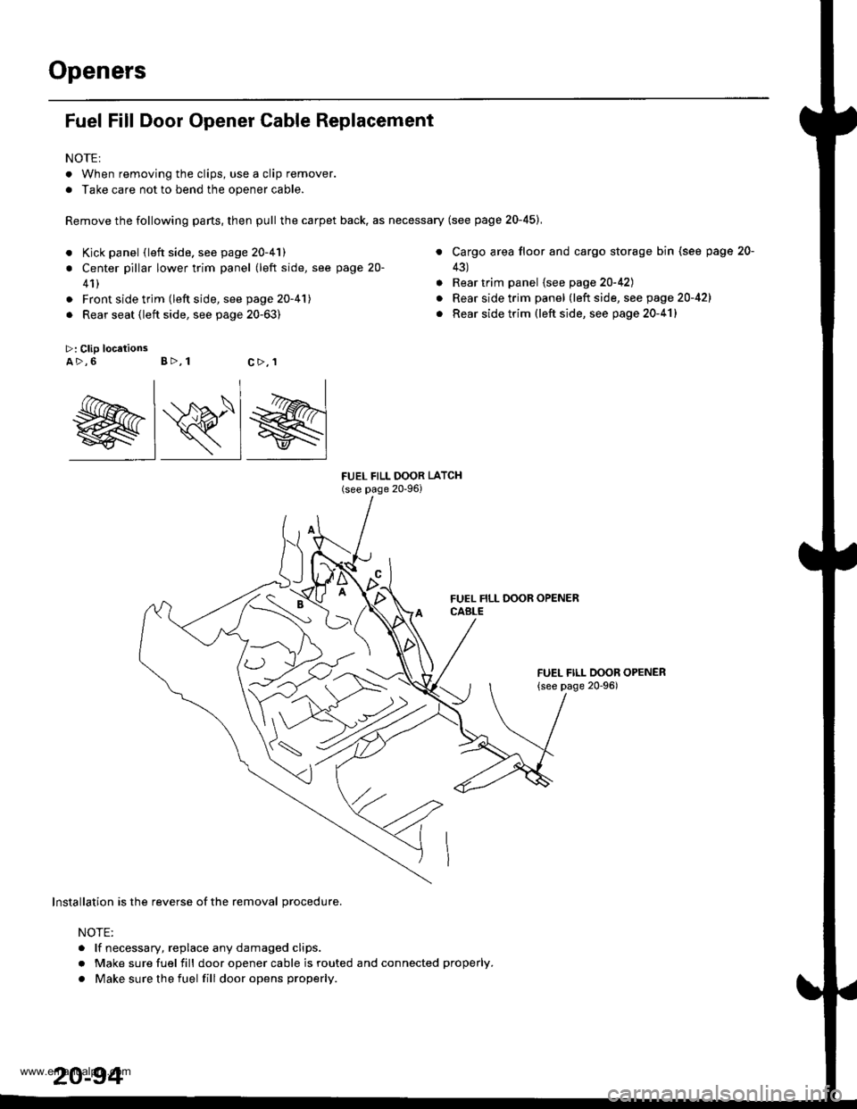
Fuel Fill Door Opener Cable Replacement
NOTE:
. When removing the clips, use a clip remover.
. Take care not to bend the opener cable.
Remove the following parts, then pull the carpet back, as necessary (see page 20-45),
a
>: Clip locationsA>,6 B>, 1
a
a
FUEL FILL OOOR LATCH(see page 20-96)
Kick panel (left side. see page 20-41)
Center pillar lower trim panel (left side, see page 20-
41)
Front side trim (left side, see page 20-41)
Rear seat (left side, see page 20-63)
Cargo area floor and cargo storage bin (see page
43)
Rear trim panel {see page 20-42)
Rear side trim panel (left side, see page 20-421
Rear side trim (left side, see page 20-41)
FUEL FILL DOOR OPENER
{see page 20-96)
20-
c>,1
@lRlg
Installation is the reverse of the removal procedure.
NOTE:
. lf necessary, replace any damaged clips.
r Make sure fuel fill door opener cable is routed and connected properly.
. Make sure the fuel fill dooropens properly.
www.emanualpro.com
Page 1082 of 1395
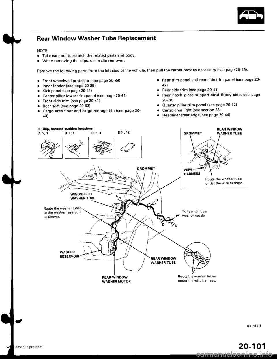
Rear Window Washer Tube Replacement
NOTE:
. Take care not to scratch the related parts and body.
. When removing the clips, use a clip remover.
Remove the following parts from the left side of the vehicle, then
. Front wheelwell protector (see page 20-89)
. Innertender (see page 20-89)
. Kick panel (see page 20-4't)
. Center pillar lower trim panel (see page 20-41)
. Front side trim (see page 20-41)
. Rear seat (see page 20-63)
a Cargo area floor and cargo storage bin (see page 20-
43)
>: Clip, harness cu3hion location3c>,3D>,12A>, 1B>, 1
Route the washer t!be
under the wire harness
Route the washer tubesto the washer reservoir
WASHEBRESERVOIR
wasner no2zre.
@s_l el 4
WINDSHIELDWASHEB TUBE
REAR WINDOWWASHER MOTOR
GROMMET
wrNoowWASHER TUBE
pull the carpet back as necessary (see page 20-45)
. Rear trim panel and rear side trim panel (see page 20-
42J
. Rear side trim (see page 20-41)
. Rear hatch glass support strut (body side, see page
20-7Al
. Ouarter pillartrim panel (see page 20-421
o Cargo area light (see section 23)
. Headliner (rear edge, see page 20-44)
GROMMET
(cont'd)
20-101
www.emanualpro.com
Page 1171 of 1395

Gonnector ldentification and Wire Harness Routing
How to ldentity Connectors:
ldentification numbers have been assigned to all connectors, The number is preceded by the letter "C" for connectors.
"G" for ground terminals or "T" for non-ground terminals.
Location
HarnessEngine CompartmsntDashboardOthers lFloor, Door,
8oof, Tailgate)
Starter cableT1, T2 and @
Battery ground cableG1 and O
Engine ground cableT3
Transmission ground cableT4
G3
Engine wire harnessC101 through C137
T101 and T102
G101
Engine compartment ware harnessC201 through C218
G201 and G202
Under-hood ABS fuse/relay box
wire harness
t5ano9
Main wire harnessC301 through C309
C351 through C361
C401 through C447
G401 and G402
Dashboard wire harnessC501 through C524 (C525)
G501
Left side wire harnessC551 through C581
G551, G552 and G553
Right side wire harnessC601 through C605
lnterior wire harnessC701 through C703
Rear bumper wire harnessC641 through C643
Heater sub-harnessC731 through C740
Secondary heated oxygen sensor
sub-harness
C721 through C722
Combination switch sub-harnessC751 through C760
Driver's door wire harnessC661 through C667
Front passenger's door wire harnessC6Tl through C676
Left rear door wire harnessC681 through C684
Right rear door wire harnessC69'l through C694
Rear wire harnessC611 through C520
Tailgate wire harnessC631 through C634
G631
SRS main harnessC801 through C808
G801
High mount brake light sub-harnessC651 through C653
Fuel tank oressure sensor sub-harnessC645 through C647
www.emanualpro.com
Page 1180 of 1395

Connector ldentification and Wire Harness Routing
Main Wire Harn€ss (left side of dash and floor branchesl {cont,dl
c401
c402
c403
c404
c404
c405
c406
c407
c408
c409
c410
c410
c411
c412
c413
c413
c414
c415
c416
c416
c417
c418
c419
c420
c420
c421
c422
c423
c424
c425
c42A
c426
c437
c438
c438
c439
c440
c441c442
5
20
20
24
't4
8
5
3
12
10'1
18
20'18
10
15
1
4
8
5
5
22
Behind left kick panel
Behind left kick panel
Behind left kick panel
Behind left kick panel
Behind left kick panel
Under left side of dashUnder left side of dashUnder left side of dashUnder left side of dashUnder left side of dashUnder left side of dashUnder left side of dash
Under left side of dashUnder left side of dashUnder left side of dash
Under left side of dash
Under left side of dashUnder left side of dashUnder left side of dashUnder left side of dashUnder left side of dashUnder left side of dashUnder left side of dashUnder left side of dash
Under left side of dashUnder left side of dashUnder left side of dashUnder middle of dashUnder middle of dashUnder middle of dashUnder middle of dashUnder middle of dash
Under left side of dashUnder left side of dash
Under left side of dashUnder left side of dashUnder left side of dashUnder left side of dashUnder left side of dash
Under left side of dash
Under left side of dashUnder left side of dashUnder left side of dashUnder left side of dash
Starter cut relay
Horn relay
Left side wire harness (C558)
Left side wire harness (C559)
Left side wire harness (C559)
Cruise control unitDaytime running lights control unitDaytime running lights control unitlgnition key light control unitInterior wire harness {C701)Cable reel
Cable reel
lgnition key switchlgnition key switch
Combination switch sub-harness {C753)
Combination switch sub-harness (C753)
SRS main harness (C803)
Dashboard wire harness (C503)
Dashboard wire harness (C501)
Dashboard wire harness {C501)Under-dash fuse/relay box (C922)
Under-dash fuse/relay box (C920)
Under-dash fuse/relay box (C919)
lntegrated control unit
Integrated control unitFront fog lights switchBrake switch
Interlock control unitReverse relay
Rear accessory socket relayRear accessory socket relayRear heated oxygen sensor sub-harness (C722)
Security control unitSecurity starter cut relay (for securityalarm system)
Junction connector (for interlock system)Security wire harnessSecurity wire harnessRear window wiper control unitCombination switch sub-harness (C760)
Combination switch sub-harness (C760)
Securlty indicatorSecurity valet switchClutch interlock switchClutch switch (for cruise control)
'97 model'98 - 00mooets
Canada
Canada'97 model
'97 model'98 - 00models
'97 - 98models'99 - 00
moqets
'97 model'98 - 00mooets
Optional
Optional
Optional
Optional
Optional'97 model
'97 - 98mooels'99 - 00models
OptionalOptional
Mfi
Mlr
Under left side of dashBody ground, via main wire harness
23-20
www.emanualpro.com
Page 1182 of 1395
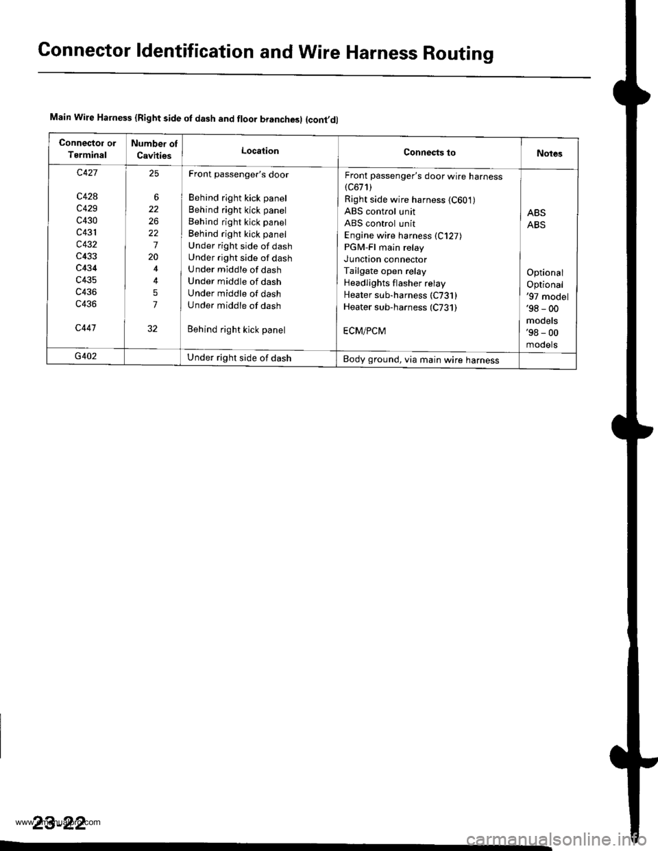
Connector ldentification and Wire Harness Routing
Main Wire Harness {Right side of dash and floor branchesl {cont,dl
Connector or
Tsrminal
Number ol
CavitiesLocationConnects toNotes
c427
c428
c429
c430
c431
c432
c433
c434
c435
c436
c436
c447
6
26
22
7
20
5
7
25Front passenger's door
Behind right kick panel
Behind right kick panel
Behind right kick panel
Behind right kick panel
Under right side of dash
Under .ight side of dash
Under middle of dash
Under middle of dash
Under middle of dash
Under middle of dash
Behind right kick panel
Front passenger's door wire harness(c671)
Right side wire harness {C601)ABS control unit
ABS control unit
Engine wire harness (C127)
PGM-Fl main relay
JUnotron connector
Tailgate open relay
Headlights f lasher relay
Heater sub-harness (C731 )Heater sub-harness (C731)
ECM/PCM
ABS
ABS
Optional
Optional'97 model'98 - 00
models'98 - 00
mooets
G402Under right side of dashBody ground, via main wire harness
23-22
www.emanualpro.com