canister HONDA CR-V 1999 RD1-RD3 / 1.G Owner's Manual
[x] Cancel search | Manufacturer: HONDA, Model Year: 1999, Model line: CR-V, Model: HONDA CR-V 1999 RD1-RD3 / 1.GPages: 1395, PDF Size: 35.62 MB
Page 407 of 1395

'97 model:
The scan tool indicates Diagnostic Trouble Code (DTC) P0441: Evaporative Emission (EVAP) control system
insufficient purge flow.
Description
By monitoring the purge line vacuum with the MAP sensor, the PCM can detect insufficient EVAP control system purge
flow.
Possiblo Cause
. EVAP Purge Control Solenoid Valve
. EVAP Purge Control Solenoid Valve Circuit
. EVAP Control Canister
. Vacuum Lines
. PCM
Troubleshooting Flowchart
EVAP PURGE CONTROL
SO1TNOID VALVE 2P
CoNNECTOR (C108)
(v)
YL
Wire side of female
termrnals
(cont'd)
11-205
Th€ MIL has b€en reooited on.DTC P0441 is .tored.
Problem verificationl1. Start the engine. Hold theengine at 3,000 rpm with noload (in Park or neut.al) untilthe radiator fan comes on.2. Do the PCM Reset Procedure.3. Connect the SCS service con-nector,4. Test drive under following con'ditions on the road.- without any electrical load- Transmission in @ or @position- Engine speed between1 ,2OO - 2,4OO rpfi.- Decelerate from 50 mph (80
km/h)to 15 mph (24 km/h)Intermittent trilure, sydern is OKat this time. Check for Door con-nections or loose wir€3 at C108
IEVAP purge control solonoidvalvol .nd at the PCM.
ls DTC P0441 indicated?
Check tor an open in the wire (lcl
linel:1. Turn the ignition switch OFF.2. Disconnect the EVAP purge
control solenoid valve 2P con-nector.3. Turn the ignition switch ON (ll).
4. Measure voltage between bodyground and the EVAP purge
control solenoid valve 2P con-nector terminal No. '1,
R€pafu open in thc wir6 b€tw€enthG EVAP purge control solenoidvalve and the No. 15 ALTEBNA-TOR SP SENSOR (7.5 A)fuse.
ls there batlery voltage?
(To page 11'206)
www.emanualpro.com
Page 409 of 1395
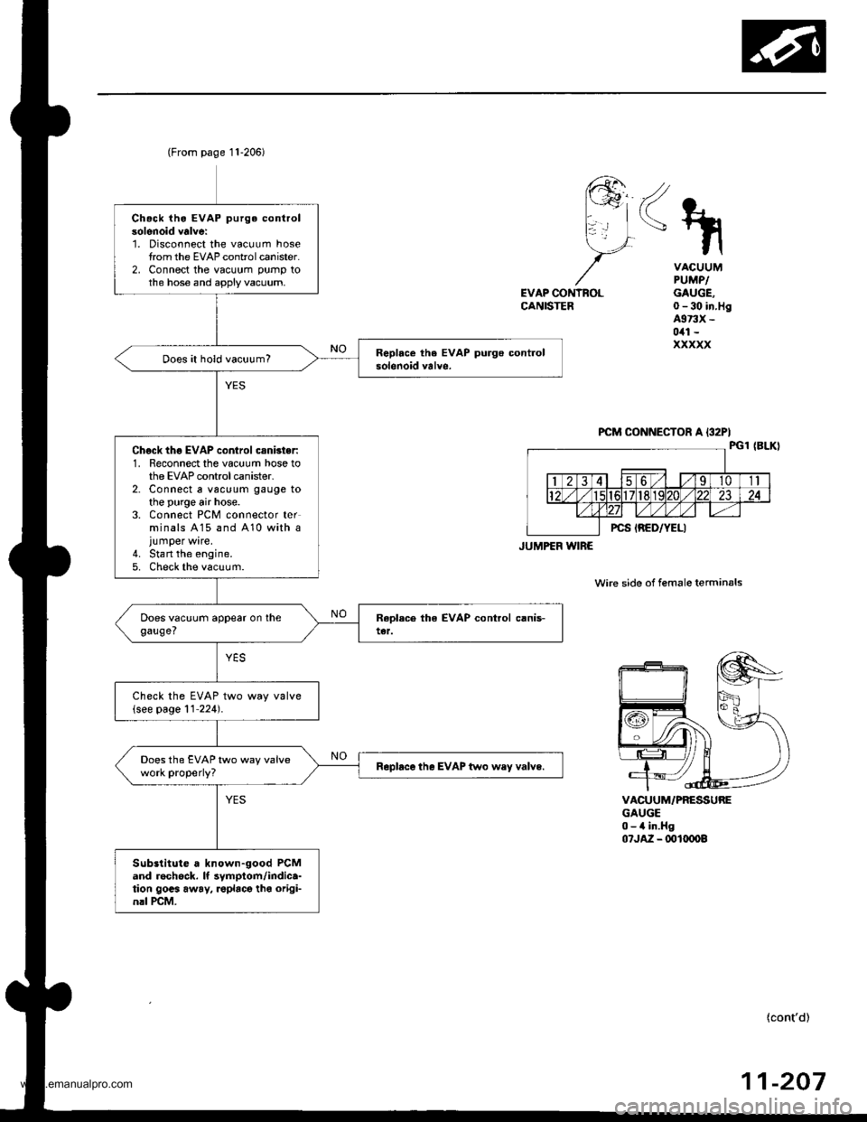
Chack iho EVAP purge controlsolenoid valve:1. Disconnect the vacuum hosetrom the EVAP controlcanister.2, Connect the vacuum pump tothe hose and apply vacuum,
Does it hold vacuum?
Chgck thg EVAP control csnbter:1. Reconnect the vacuum hose tothe EVAP control canister.2. Connect a vac!um gauge tothe purge air hose.3. Connect PCM connector terminals A15 and 410 with ajumper wire.4. Stan the engine.5. Check the vacuum.
Check the EVAP two way valve(see page 11'224).
Does the EVAP two way valvework properly?Rapbce the EVAP two wey valve.
Substitute a known-good PCMand rechock. It symptom/indica-tion gocs away, roplacg tho origi-nrl rcM.
(From page 11-206)
JUMPEF WIRE
<\
EVAP CONTNOLCANISTER
VACUUMPUMPIGAUGE,0-30 in.Hg4973X -
0il1 -
xxxxx
VACUUM/PRESSUREGAUGE0-4 in.Hg07JA2 - ml(x)o8
wire side of female terminals
{cont'd)
-20711
www.emanualpro.com
Page 417 of 1395
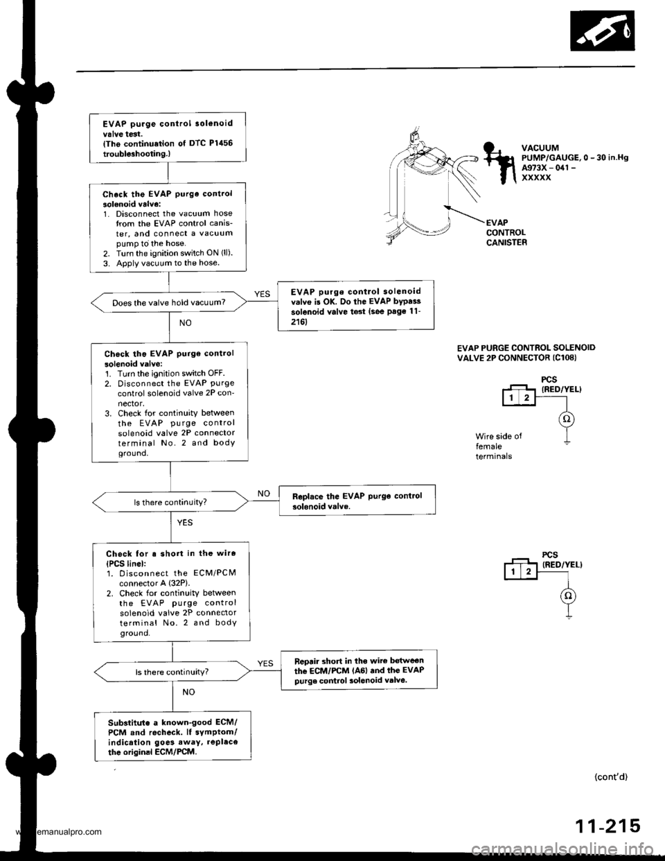
EVAP purge control 3ol€noidvalve test.{Tho continu.tion of DTC Plil56
trouble3hootin9.)
Check the EVAP purge control
solenoid valve:1. Disconnect the vacuum hosetrom the EVAP control canis-
ter, and connect a vacuumpump to the hose.2. Turn the ignition switch ON (ll).
3. Apply vacuum to the hose.
EVAP purge contlol solenoidv.lvo is OK. Do the EVAP bypai3
solenoid valve test (see Page 11-
2161
Does the valve hold vacuum?
Check tho EVAP purge control
solenoid valve:'t. Turn the ignition switch OFF.2. Disconnect the EVAP Purgecontrol solenoid valve 2P con-nector,3. Check for continuity between
the EVAP pu rge controlsolenoid valve 2P connectorterminal No.2 and bodYground,
Check for s short in the wire
{PCS linel:1. D iscon nect the ECM/PCMconnector A {32P).2. Check for continuity betweenthe EVAP purge controlsolenoid valve 2P connectorterminal No. 2 and bodyground.
neprir short in tho wite bot$reon
the ECM/FCM lAGl and thc EVAPpurge control 3olenoid valve.ls there continuity?
Substitut€ a known-good ECM/
PCM and recheck. lf symptom/indication goe3 away. repl.ce
thc originsl ECM/PCM.
VACUUMPUMP/GAUGE,0 - 30 in.HgA973X - 041 -
xxxxx
EVAPCONTROLCANISTER
EVAP PURGE CONTROL SOLENOIDVALVE 2P CONNECTOR (Cl08}
Wire side offemaleterminals
(cont'd)
-21511
www.emanualpro.com
Page 419 of 1395
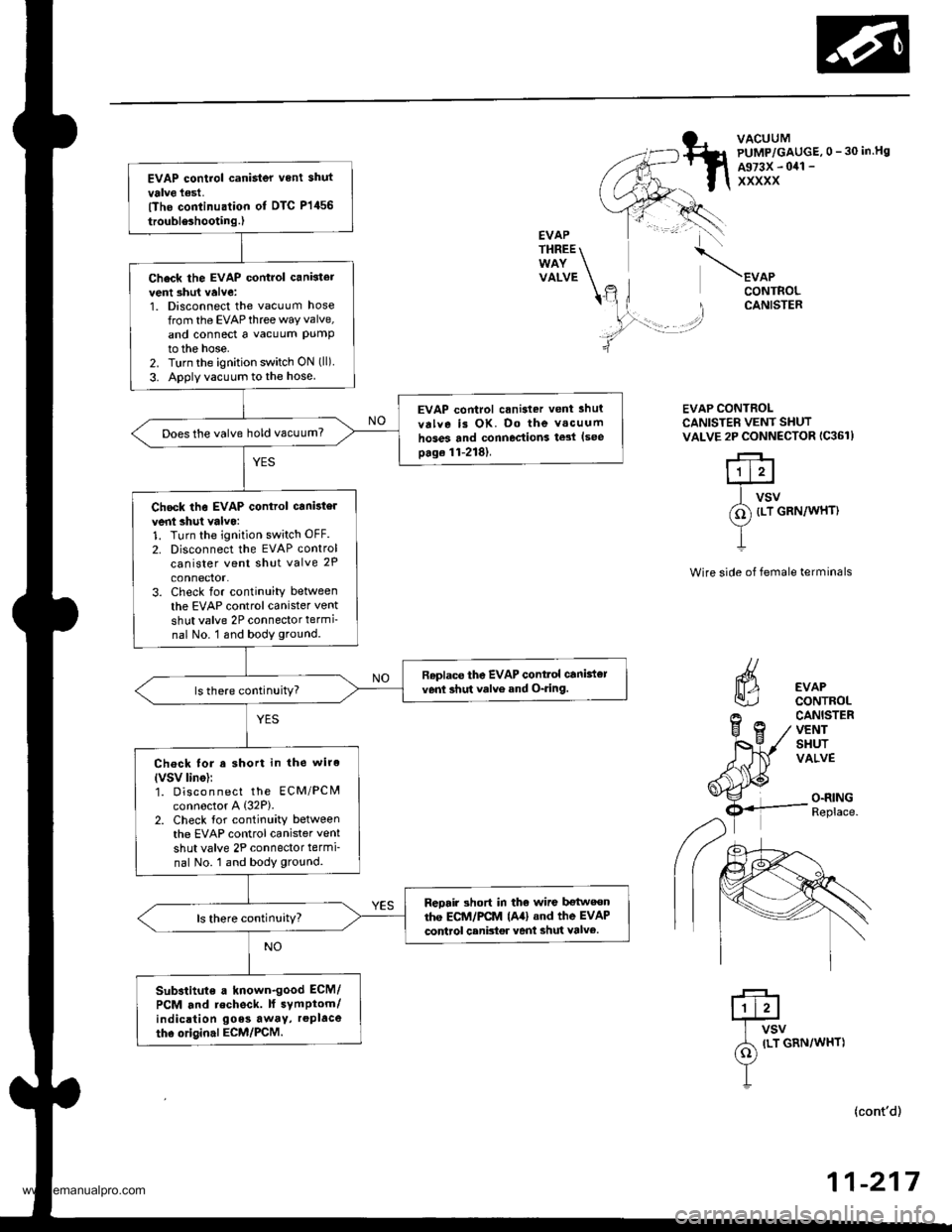
EVAP control canister vent shut
valve l€st,lThe conlinualion ot DTC P1456
troubleshooting.)
Check the EVAP control cankter
vent 3hut valve:1. Disconnect the vacuum hose
from the EVAPthree way valve,
and connect a vacuum PUmPto the hose.2. Turn the ignition switch ON (ll).
3. Apply vacuum to the hose
EVAP control crnisier vent lhul
valve is OK. Do the v.cuum
hoses and connections te3l lseepage 11-218).
Does the valve hold vacuum?
Chock the EVAP control canbtel
vent shul valvo:1. Turn the ignition sw;tch OFF.
2. Disconnect the EVAP controlcanister vent shut valve 2P
connector.3. Check for continuity betlveen
the EVAP control canister vent
shut valve 2P connector termi-nal No. 1 snd body ground.
Roplac€ the EVAP contlol canbt€]venl shut valve and O-ring.
Chock lor a short in the wire(VSV lino)r1. Disco n nect the EcM/PCN4connoctor A (32P).
2. Check for continuity betweenthe EVAP control canister vent
shut valve 2P connector termi-
nal No. 1 and body ground.
Reorir 3hort in tho wiro bgtweonthe EC1I/I/PCM lAal .nd the EVAP
codrol canbtor vent shut valv6.
Substitute a known.good ECM/
PCM and recheck. lf symptom/indicrtion goes awaY, replace
the original ECM/PCM.
VACUUMPUMP/GAUGE,0 - 30 in.Hg
A973X - 041 -
XXXXX
EVAPTHREE
VALVEEVAPCONTROLCANISTER
EVAP CONTROLCANISTER VENT SHUTVALVE 2P CONNECTOR IC361)
r+l1t2l
f1 VSV
(o) tLT cnrulwxrt
1
Wire side of female terminals
EVAPCONTROLCANISTERVENTSHUTVALVE
O.RINGReplace.
ILT GRN/WHT)
(cont'd)
-21711
www.emanualpro.com
Page 421 of 1395
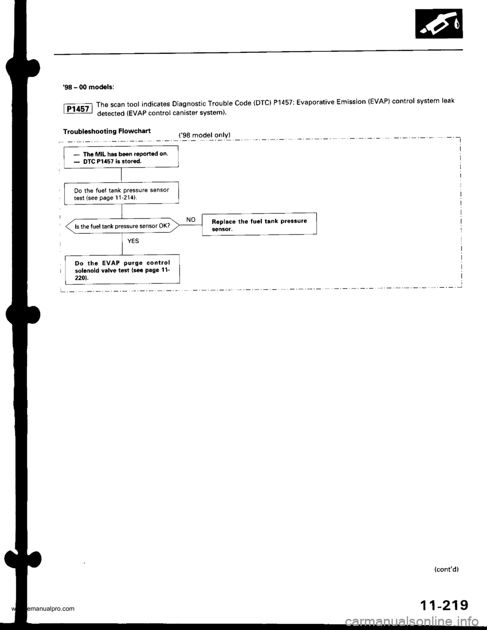
'98 - 00 mod€ls:
The scan tool indicates Diagnostic Trouble code (DTc) P1457: Evaporative Emission (EVAP) Control system leak
detected (EVAP control canister system).
Troubl6shooting Flowchart('98 model only)_]
I
- The MIL has been rePorted on.- DTC P1,157 is storod.
Do the fuel tank Pressure sensor
test {see page 11-214).
ls the {ueltank pressure sensor OK?
Do the EVAP Purge contlol
solenoid valve test lsea Page 1l_
220t.
(cont'dl
11-219
www.emanualpro.com
Page 422 of 1395
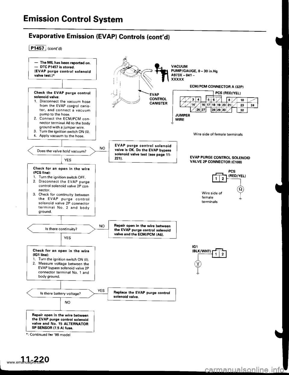
Emission Control System
Evaporative Emission (EVAP) Controls (cont,dl
iTl457l ("ont'or
APCONTROLCANISTER
Ropair op€n in th6 wire betweenthe EVAP purge control 3olenoidvelve and ths ECM/PCM (A61.
VACUUMPUMP/GAUGE, O-30 iN.HgA973X - 0rl -
xxxxx
'\)
Wire side of lemale terminals
EVAP PURGE CONTROL SOI.ENOIDVALVE 2P CONNECTOR (Cl08)
PCSIRED/YELI
femaletermanals
ECM/PCM CONNECTOR A {32P}
PCS (RED/YELI
,/3 458/'t0
,,/ 14 ,/'t61718l92024
,/ 262930
JUMPERWIRE
- The MIL has been reported on.- DTC P1457 is stored.{EVAP purge control solenoidvalve test.l*
Check the EVAP purge conrrol30lenoid velve:L Disconnect the vacuum hosefrom the EVAP conlrol canis,ter, and connect a vacuumpump to the hose.2. Connect the ECM/PCM connector terminal A6 to the bodyground with a jumper wire.3. Turn the ignition switch ON (tl).4. Apply vacuum to the hose.
EVAP purge control solenoidvalve is OK. Oo the EVAP bypasssolenoid valve t€3t {see psge 1l-221t.
Does the valve hold vacuum?
Check for an open in the wire(PCS line):1. Turn the ignition switch OFF.2. Disconnect the EVAP purgecontrol solenoid valve 2P connector,3. Check for continuity betweenthe EVAP pu rge controlsolenoid valve 2P connectorterminal No.2 and bodygrouno,
ls there continuity?
Check for an open in the wire(lGl line):1. Turn the ignition switch ON t).2. Measure voltage between theEVAP bypass solenoid valve 2pcoonector terminal No. 1 andbody ground.
ls there battery voltage?
Repah open in lhe wir6 betwoenthe EVAP pu.ge cont.ol solonoidvdlvo and No. 15 ALTERNATORSP SENSOR {7.5 Al fu!€.
*: Continued frr '98 model
1-220
www.emanualpro.com
Page 424 of 1395
Emission Control System
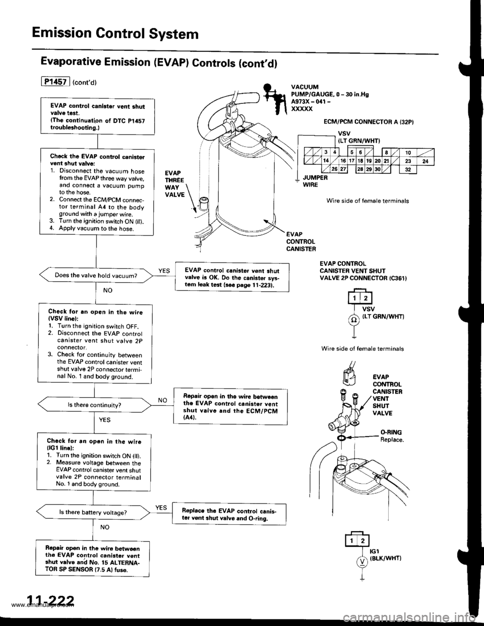
Evaporative Emission (EVAP) Controls (cont,dl
lT145il ("ont'o)
EVAPTHREE
VATVE \'t
VACUUMPUMP/GAUGE,0 - 30 in.HsA973X - 041 -
xxxxx
WIRE
ECM/PCM CONNECTOR A {32PI
vsv
Wire side of female terminals
EVAPCONTROLCANISTER
EVAP CONTROLCANISTER VENT SHUTVALVE 2P CONNECTOR {C361}
riErr+J
I vsv
/A {Lr GRN/WHT|
YI
Wire side of female terminals
CANISTEFVENTSHUTVALVE
EVAPCONTROL
(}BING
Replace.
ffilrcr
e
(BLK/wHr)
I
11-222
EVAP control canistor vent shutvalve t6t.(The continuation of DTC p1457
troubl€ahooting.)
Chcck the EVAP control c.nirt6lvent ahut vrlve:1. Disconnect the vacuum hosetrom the EVAP thre€ way valve,and connect a vacuum pumpto the hose.2. Connect the ECM,PCM conn6c,tor terminal A4 to the bodyground with a jumper wire.3. Turn the ignition switch ON fil).4. Applyvacuum to the hose.
EVAP control crni3ter v6nt shutvelve b OK. Do the canistsr sys-lern loak test {3ee page 11-2231.
Does the valve hold vacuum?
Check for an open in the wireIVSV linGll1. Turn the ignition swjtch OFF.2. Disconnect the EVAP controlcanister vent shut valve 2pconnector.3. Check for continuity betweenthe EVAP control canister ventshul valve 2P connector termi-nal No. l and body ground.
Ropril op6n in tho wire botweonthe EVAP control canister v6ntshut v.lve and the ECM/PCM(A41.
Check tor an open in the wire(lGl line):1. Turn the ignition switch ON l).2. Measure voltage between theEVAP control canister vent shutvalve 2P connector terrninalNo. 1 and body ground.
Roplace thG EVAP cont.ol canis-ter Yent shut velve and O-ring.
Repai. opon in the wire betwoenth6 EVAP control canister vontshut valve .nd No. 15 ALTERNA-TOB SP SENSOR t?.5 Alfus6.
{LT GRN/WHT)
36a10
l4/1617l8't9202l232426 272a2930
JUMPER
www.emanualpro.com
Page 425 of 1395
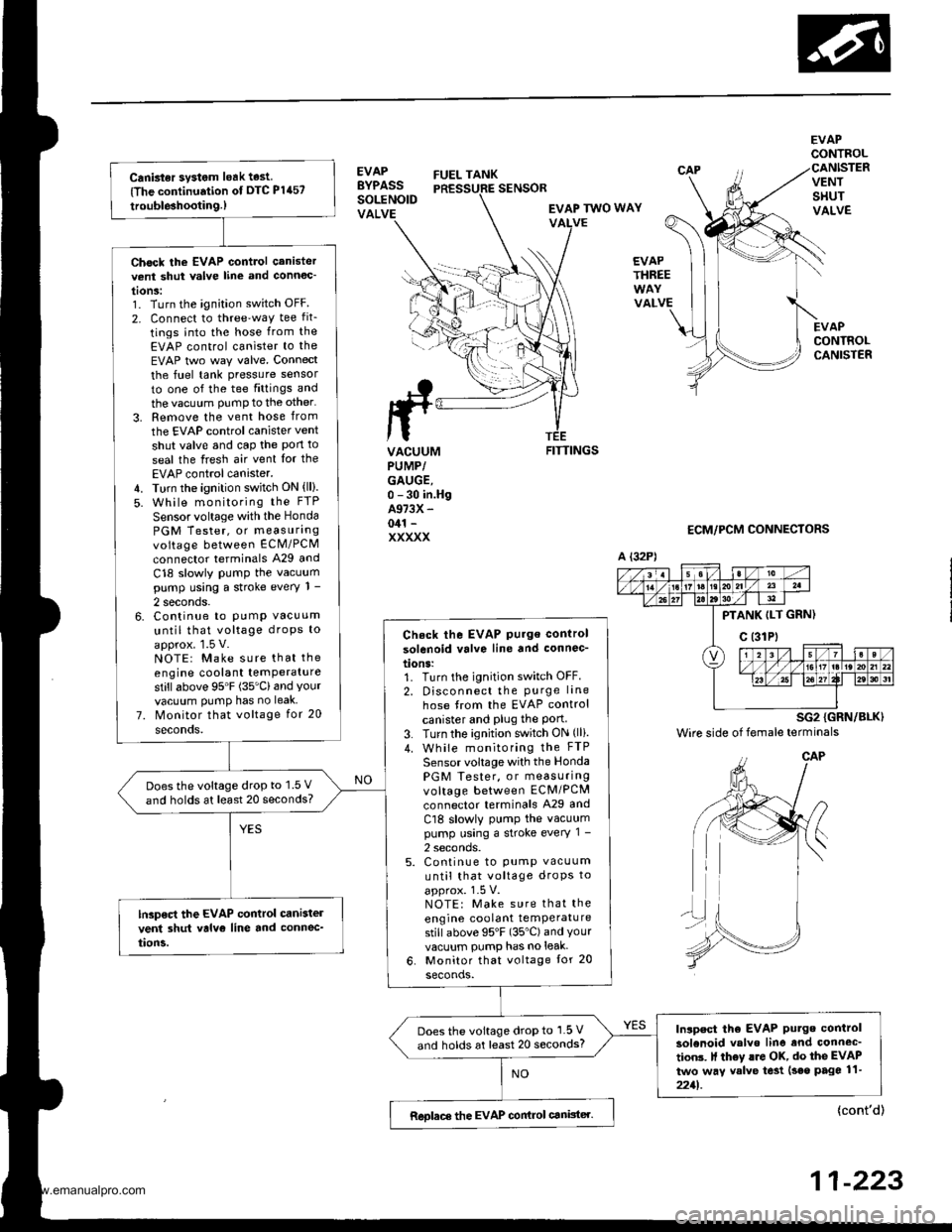
Canbter system leak test
{The continuation of DTC P1457
trouble3hootin9.)
Chock the EVAP control canistervent shut valve line and connoc'
tonS:1. Turn the ignition switch OFF
2. Connect to three'way tee fit_
tings into the hose from the
EVAP control canister to the
EVAP two way valve. Connect
the fuel tank pressure sensor
to one of the tee fittings and
the vacuum PumP to the other'
3. Remove the vent hose from
the EVAP control canister vent
shut valve and cap the Pon to
seal the fresh air vent Ior the
EVAP control canister.4. Turn the ignition switch ON (ll).
5. While monitoring the FTP
Sensor voltage with the Honda
PGM Tester, or measurangvoltage between ECM/PCM
connector terminals A29 and
C18 slowly PumP the vacuumpump using a stroke every 1 -
2 seconds.6. Continue to PumP vacuum
until that voltage droPs to
approx. 1.5 V.NOTE: Make sure that the
engine coolant temPeraturestillabove 95'F (35'Cland Yourvacuum PumP has no leak
7. Monitor that voltage for 20
seconds.
Check the EVAP Pu.ge control
solenoid valve line and connec-
tions:1. Turn the ignition switch OFF.
2. Disconnect the Purge lane
hose from the EVAP control
canister and Plug the Port3. Turn the ignition switch ON (lli.
4. While monitoring the FTP
Sensor voltage with the Honda
PGM Tester, or measuringvoltage between ECM/PCM
connector terminals A29 and
Cl8 slowly PumP the vacuumpump using a stroke every 1 -
2 seconds.5. Continue to pump vacuum
until that voltage droPs to
approx. 1-5 V.NOTE: Make sure that the
engine coolant temPeraturestill above 95'F (35"C) and Yourvacuum pump has no leak-
6. Monitor that voltage tor 20
seconds.
Doesthe voltage drop to 1.5 V
and holds at least 20 seconds?
lGp€ct the EVAP control cani3tel
vent 3hut valvo line and connec_
tion5.
Inlpect tho EVAP Putge control
solenoid valvo line and connec'
tion3. It th6y lro OK, do the EVAP
two way valve te3t (seo page 11-
2211.
Does the voltage drop to 1.5 V
and holds at least 20 seconds?
Reolace the EVAP conirol canister.
EVAPBYPASSSOLENOIDVALVE
FUEL TANK
EVAPCONTROL
VENTSHUTVALVE
EVAPCONTROLCANISTER
SENSOR
EVAP TWO WAYVALVE
EVAPTHREE
VALVE
ttrrL
ta
VACUUMPUMP/GAUGE,0 - 30 in.HgA973X -
041 -
XXXXX
FITTINGS
ECM/PCM CONNECTORS
A {32P)
PTANK ILT GRN)
c (31Pt
SG2 {GRN/BLK)
Wire side of female terminals
{cont'd)
11-223
www.emanualpro.com
Page 426 of 1395
Emission Control System
Evaporative Emission (EVAP) Controls (cont,dl
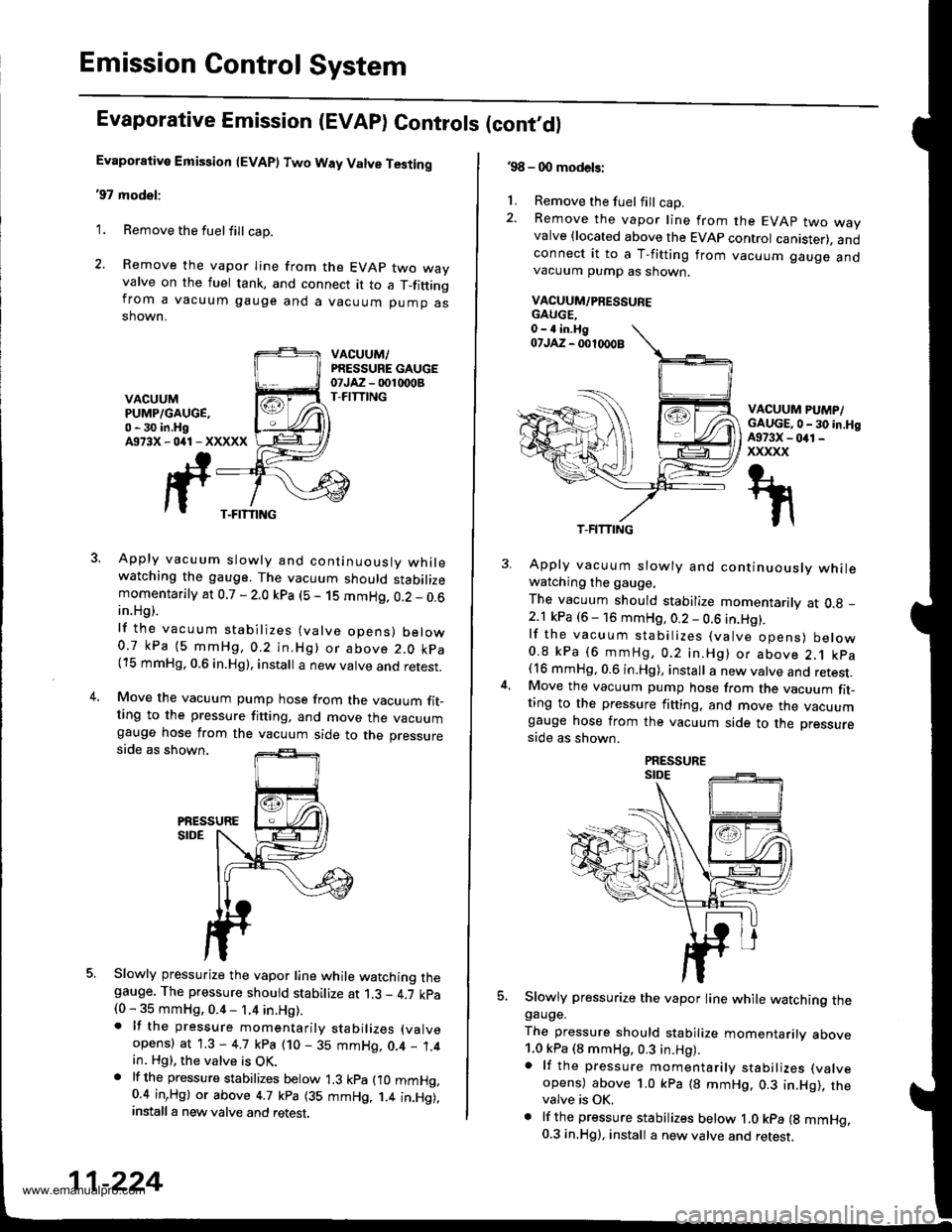
Evaporative Emission (EVAP) Two Way Valve Testing
'97 model:
1. Remove the fuelfill cap.
2. Remove the vapor Iine from the EVAP two wayvalve on the fuel tank, and connect it to a T_fittingfrom a vacuum gauge and a vacuum pump asshown.
VACUUM,/PRESSURE GAUGEotJAz - 001 rDoBT-FITTINGVACUUMPUMP/GAUGE,0 - 30 in.HgA973X-041-XXXXX
3. Apply vacuum slowly and continuouslv whilewatching the gauge. The vacuum should stabilizemomentarily at 0.7 - 2.0 kpa (5 - 1S mmHg, 0.2 _ 0.6in.Hg).
lf the vacuum stabilizes (valve opens) below0.7 kPa (5 mmHg,0.2 in,Hg) or above 2.0 kpa(15 mmHg, 0.6 in.Hg), install a new valve and retest.
4.Move the vacuum pump hose from the vacuum fit_ting to the pressure fitting, and move the vacuumgauge hose from the vacuum side to the pressureside as shown.
PiESSURESIDE
5. Slowly pressurize the vapor line while watching thegauge. The pressure should stabilize at 1.3 - 4.7 kpa(0 - 35 mmHg, 0.4 - 1.4 in.Hg).. lf the pressure momentarily stabilizes (valve
opens) at 1.3 - 4.7 kpa (10 - 35 mmHg, 0.4 _ 1.4in. Hg), the valve is OK.. lf th6 pressure stabilizes below 1.3 kpa fio mmHg,0.4 inrHg) or above 4.7 kpa (35 mmHg, 1.4 in.Hg),install a new valve and retest.
T-FITTING
11-224
.98 - 0O models:
1. Remove the fuel fill cap.2. Remove the vapor line from the EVAP two wayvalve {located above the EVAP control canister). andconnect it to a T-fitting from vacuum gauge andvacuum pump as shown.
VACUUM/PRESSUFE
VACUUM PUMP/GAUGE,0 - 30 in.HgA973X - 041 -
xxxxx
5.
Apply vacuum slowly and continuously whilewatching the gauge.
The vacuum should stabilize momentarily at O.g _
2.1 kPa (6 - 16 mmHg, 0.2 - 0.6 in.Hg).lf the vacuum stabilizes (valve opens) below0.8 kPa (6 mmHg, 0.2 in.Hg) or above 2.1 kpa(16 mmHg, 0.6 in.Hg), install a new valve and retest.Move the vacuum pump hose from the vacuum fit-ting to the pressure fitting. and move the vacuumgauge hose from the vacuum side to the pressure
side as shown.
Slowly pressurize the vapor line while watching thegauge.
The pressure should stabilize momentarilv above1.0 kPa (8 mmHg, 0.3 in.Hg).a lf the pressure momentarily stabilizes (valve
opens) above 1.0 kPa (8 mmHg. 0.3 in.Hg), thevalve is OK.. lf the pressure stabilizes below ,|.0 kpa {g mmHg.0.3 in.Hg), install a new valve and retest.
T-FITTING
www.emanualpro.com
Page 1178 of 1395
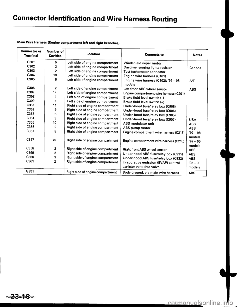
Gonnector ldentification and WireHarness Routing
Main Wire Harness lEngine compartmont left and right branches)
Connectot ol
Terminal
Number ot
CavitiesLocationConneqts toNot€s
c301
c303
c304
c305
c306
c307
c308
c309
c352
c354
c356
c357
c358
c359
c360
LJO I
5
2
10
'14
1
1
t1
3
10
8
10
2
Left side of engine compartment
Left side of engine compartment
Left side of engine compartment
Left side of engine companment
Left side of engine compartment
Left side of engine compartment
Left side of engine compartment
Left side of engine compartment
Left side of engine compartment
Right side of engine compartment
Right side of engine compartment
Right side of engine compartment
Right side of engine compartment
Right side of engine compartment
Right side of engine compartment
Right side of engine compartment
Right side of engine compartment
Right side of engine compartment
Right side of engine compartment
Right side of engine compartment
Right side of engine compartment
Windshield wiper motor
Daytime running lights resistor
Test techometer connector
Engine wire harness (C10])
Engine wire harness (C102): '97 - 98models
Left front ABS wheel sensor
Engine compartment wire harness (C201)
Brake fluid level switch {-)Brake fluid level switch (+)
Under-hood fuse/relay box (C908)
Under-hood fuse/relay box (C906)
Under-hood fuse/relay box (C905)
Under-hood fuse/relay box (C907)
ABS modulator unit
ABS pump motor
Engine compartment wire harness (C218)
Engine compartment wire harness (C218)
Right front ABS wheel sensor
Under-hood ABS fuse/retay box (C931)
Under-hood ABS fuse/relay box (C9321
Evaporative emission (EVAP) controcanister vent shut valve
Canada
ABS
USA
ABS
ABS'97 - 98
models'99 - 00
mooets
ABS
ABS
ABS'98 - 00
mooets
G35lRight side of engine compartmentBody ground, via main wire harnessABS
23-18
www.emanualpro.com