AC pressure switch HONDA CR-V 1999 RD1-RD3 / 1.G Owner's Guide
[x] Cancel search | Manufacturer: HONDA, Model Year: 1999, Model line: CR-V, Model: HONDA CR-V 1999 RD1-RD3 / 1.GPages: 1395, PDF Size: 35.62 MB
Page 410 of 1395
Emission Control System
Evaporative Emission (EVAP) Controls (cont'd)
99 - 00 models:
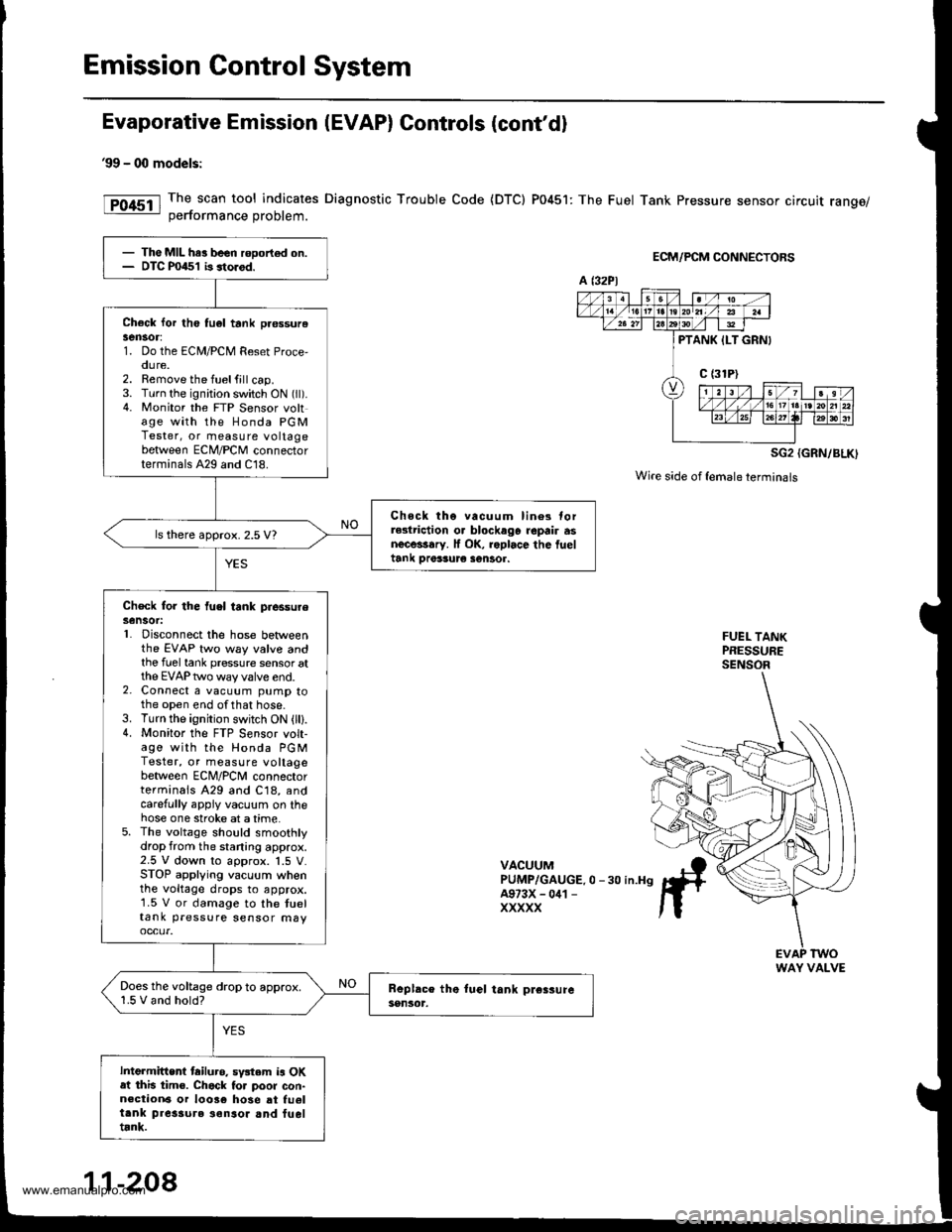
The scan tool indicates Diagnostic Trouble Code {DTC) P0451: The Fuel Tank Pressure sensor circuit range/oerformance Droblem.
ECM/PCM CONNECTORS
SG2 {GRN/BLK)
Wire side of {emaleterminals
FUEL TANKPRESSURESENSOR
VACUUMPUMP/GAUGE.0 -30 in.H9A973X - 041 -
XXXXX
- The MIL har been rooort€d on.- DTC P0451 b storod.
Check lor th6 tu6l tank pr€ssurelen30r:1. Do the ECM/PCM Reset Proce,oure.2. Remove the fuelfill cap.3. Turn the ignition switch ON (ll).4. Monitor the FTP Sensor voltage with the Honda PGMTester, or measure voltagebetween ECM/PCM connectorterminals A29 and C18.
Chock tho vacuum lin6s torrGlriction o. blockago repair asnecessary. lf OK, roplace the fueltank Drer3ur€ sentor.
ls there approx. 2.5 V?
Check for the fuel tank piessureSensot:L Disconnect the hose betweenthe EVAP two way valve andthe fuel tank pressure sensor atthe EVAP two way valve end.2. Connect a vacuum pump tothe open end ofthat hose.3. Turn the ignition switch ON (lll.4. Monitor the FTP S€nsor volt-age with the Honda PGMTester, or measure voltagebetween ECNI/PCNI connectorterminals A29 and C18, andcarefully appiy vacuum on thehose one stroke at a time.5. The voltage should smoothlydrop from the staning approx.2.5 V down to approx. 1.5 V.STOP applying vacuum whenthe voltage drops to approx.1.5 V or damage to the tueltank pressure sensor may
Does the voltage drop to approx.1.5 V and hold?
Intermittent tailuro. sv3tem is OKat this tim€. Chack to. poor con-n€ction6 or 10036 hose at fu6ltank pres3ure ionsor and fueltrnk.
a t32Pl
PTANK ILT GRNI
WAY VALVE
11-208
www.emanualpro.com
Page 411 of 1395
'98 - 00 mod€ls:
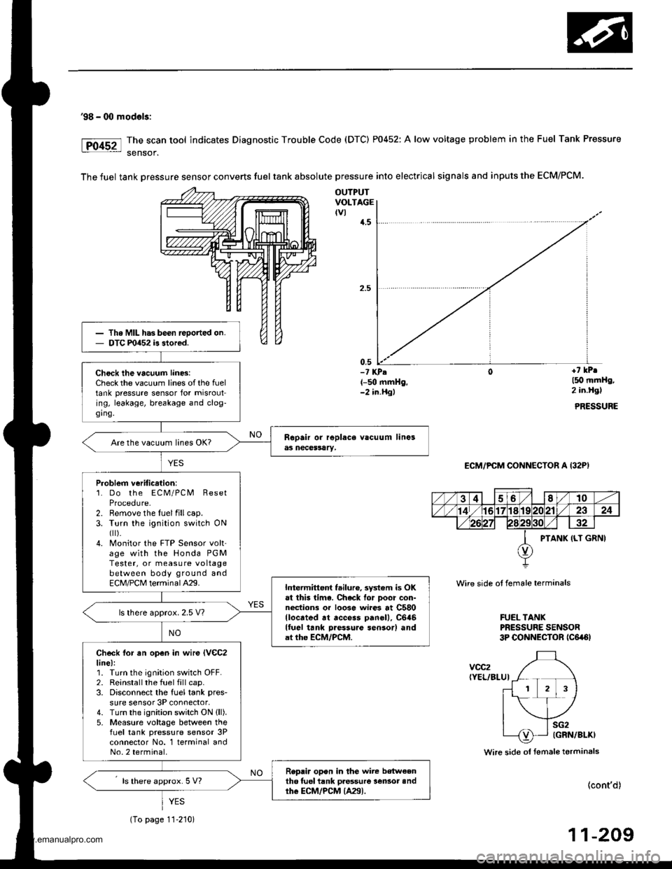
The scan tool indicates Diagnostic Trouble Code (DTC) P0452: A low voltage problem in the Fuel Tank Pressure
sensof.
The fuel tank Dressure sensor converts fuel tank absolute pressure into electrical signals and inputs the ECM/PCM.
OUTPUTVOLTAGEtvl{.5
0,5-? KPA(-50 mmHg,-2 in.Hgl
+7 kPr
l5O mmHg,2 in.Hgl
PRESSURE
ECM/PCM CONNECTOR A (32P)
Wire side ot female terminals
FUEL TANKPRESSURE SENSOR3P CONNECTOR tc6a6l
voc2(YEL/BLUI
Wire side ol fsmale terminals
(cont'd)
11-209
Th. MIL has been reoorted on.DTC m452 is stored.
Check the vacuum lin6:Check the vacuum lines of the fueltank pressure sensor for misrouting, leakage, breakage and clog-ging.
Are the vacuum lines OK?
Problem veriticstion:1. Do the ECM/PCM ResetProcedure-2. Remove the luelfillcap.3. Turn the ignition switch ONfl r).4. Monitor the FTP Sensor volt'age with the Honda PGMTester, or measure voltagebetween body ground andECM/PCM terminalA29.Intermittent failuro, system is OKat this lima. Chack lor Door con-nections or loose wi.es at C580llocrted rt access panell, C646lluel tank Daessure sensor) andat the ECM/PCM.
ls lhere approx. 2.5 V?
Check lor an open in wir€ lVeC2line):1. Turn the ignition switch OFF.2. Reinstallthe fuel fill cap.3. Disconnect the fuel tank pres-
sure sensor 3P connector,4. Turn the ignition switch ON (ll).
5- Measure voltage between thefLrel tank pressure sensor 3Pconnector No. 1 terminal andNo.2 terminal.
Replir opon in the wire b€tw€enth6 tuel tank pressure lensot andthe ECM/PCM {A29).ls there approx. 5 V?
YES
(To page 11-210)
www.emanualpro.com
Page 412 of 1395
Emission Control System
Evaporative Emission (EVAP) Controls (cont'dl
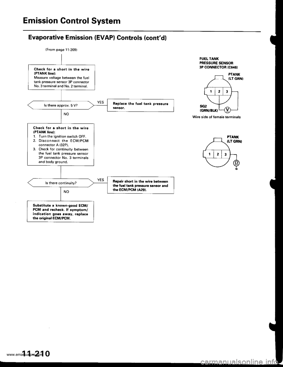
FUEL TANKPRESSUNE SENSOR3P CONNECTOR tc646l
Wire side of female terminals
(From page l1'209)
Check lor a short in the wireIPTANK Iine}:Measure voltage betlveen the fueltank pressure sensor 3P connectorNo. 3terminal and No. 2terminal.
ls there approx.5 V?
Check for a short in the wire(PTANK line):1. Turn the ignition switch OFF.2. Disco n nect the ECM/PCMconnector A {32P).3. Check for continuity betweenthe fuel tank pressure sensor3P connector No. 3 terminalsand body ground.
Repair short in the wira betwgonthe fuel trnk prossure s6nsor andtho ECM/PCM lA29).
Sub.tituto a known-good ECM/PCM and r€check. lf 3ymptom/indication goer !way. replaceth6 original ECM/PCM.
11-210
www.emanualpro.com
Page 413 of 1395
'98 - 00 modals:
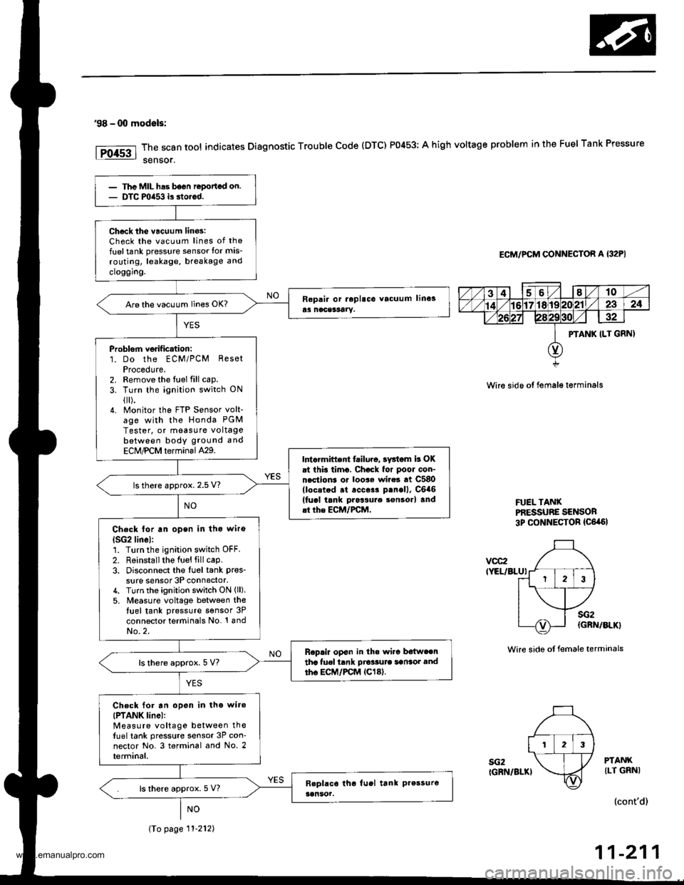
The scan tool indicates Diagnostic Trouble Code (DTC) P0453: A high voltage problem in the Fuel Tank Pressure
sensor.
ECM/PCM CONNECTOR A {32PI
Wire sido ot fema16 t€rminals
FUEL TANXPf,ESSUBE SENSOR3p CONNECTOR {C6,a6l
vcc2IYEL/BLUI
sG2IGRN/BLKI
sG2(GRN/BLK}
Wire side ot female terminals
PTANKILT GRNI
(cont'd)
11-211
PTANK ILT GRN)
123
Thc MIL has b6on ropottcd on.DTC mia53 is dorcd.
Ch6ck tho vacuum linos:Check the vacuum lines of the
fuel tank pressure sensor lor mis-
routing, leakage, breakage and
cloggrng.
Are the vacuum lines OK?
Problorn verif ication:1. Do the ECM/PCM ResetProcedute.2. Remove the fuel fill cap.
3. Turn the ignition switch ON
{[).4. Monitor the FTP Sensor volt-age with the Honda PGM
Tester, or measure voltagebetween body ground and
ECM,PCM terminal429.Intarmittent tailuro, sv3iom b OKat this timo. Chock for poor con-nection3 or loo$ wire3 at C580(locstod .t .cc$r p.nell, C6a6(fucl tank pros3ure son3orl and.t the ECM/FCM.
ls there approx. 2.5 V?
Check lor an open in tho wiro
lSG2lin6l:1. Turn the ignition switch OFF.
2. R6installthe Iuel fill cap.3. Disconnect the Iu6l tank pres_
sure sensor 3P connector,4. Turn the ignition switch ON (ll).
5. M€asure voltago between thetuel tank pressure sensor 3P
connector terminals No. '! andNo.2.
Replir op€n in th. wi.c b€{weentha fuel tank Dio'sute sansot andtho EC|,/PCM {Cl8}.ls there approx. 5 V?
Ch€ck for an opon in tho wiro(PTANK linel:Measure voltage between thefuel tank pressure sensor 3P con-nector No. 3 terminal and No. 2terminal.
ls there approx. 5 V?
\To page 11-212)
www.emanualpro.com
Page 416 of 1395
Emission Control System
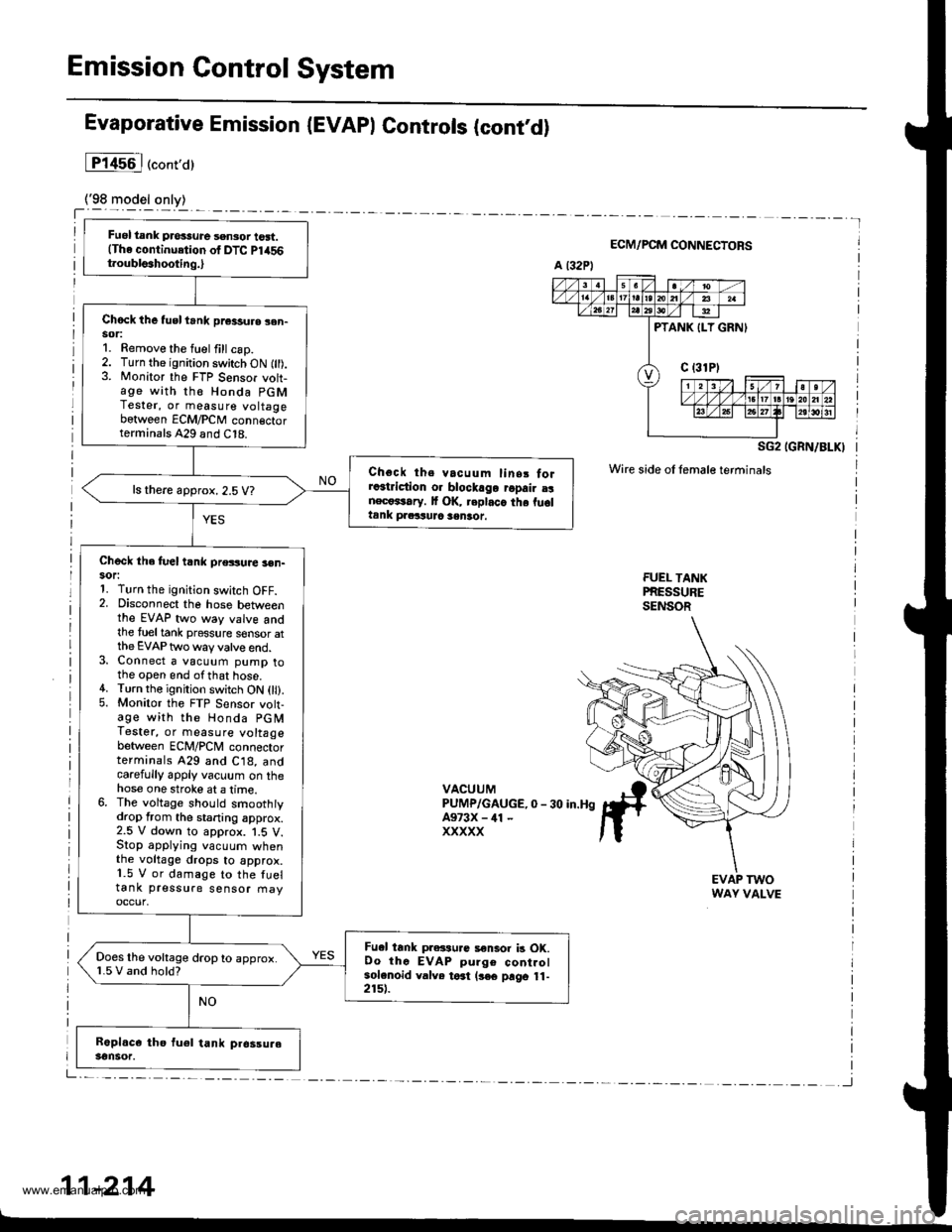
Fuel tank pros3ure sensor tost.(The continuetion of DTC Pl456t.oubls3hooting.,
Chock the tusl trnk pr€3sure sen-sor:1. Remove the fuel fill csp.2. Turn the ignition switch ON fll).3. Monitor the FTP Sensor voh-age with th€ Honda PGMTester, or measure voltagebetween ECM/PCM conn€ctorterminals A29 and C18.
Choct ths vacuum linsr forra3triction o. blockago ropair a!nect*rary. It OK, replaca the fu6ltank praituJc sentot.
ls there approx. 2.5 V?
Check the fuel t nk pressuae 3en-sor:1. Turn the ignition switch OFF.2. Disconnect the hose betweenthe EVAP two way valve andthe tueltank pressure sensor atthe EVAP two way valve end.3. Connect a vacuum pump tothe open end ofthat hose.4. Turn the ignition switch ON 0l).5. Monitor the FTP Sensor volt-age with the Honda PGMTestet, or measure voltagebetween ECM/PCM connectorterminals 429 and C18, andcarefully apply vacuum on thehose one stroke at a lime.6. The voltage should smoothtydrop from the staning approx.2.5 V down to approx. 1.5 V.Stop applying vacuum whenthe voltage drops to approx.1.5 V or damage to the fueltank pressure sensor fiayoccur,
Fu.l tank pressu.c a€nlor b OK.Oo thc EVAP pulge controlsolenoid valve toat (3€€ prgo 11-2151.
Does the voltage drop to approx.1.5 V and hold?
Evaporative Emission (EVAPI Controls (contd)
lP14s6l("ont,a)
ECM/PCM CONNECTORS
SG2 IGRN/BLKI
Wire side oI female terminals
FUEI- TANKPRESSURESENSOR
VACUUMPUMP/GAUGE,0 - 30 in.HgA973X - ill -
xxxxx
EVAP TWOWAY VALVE
11-214
www.emanualpro.com
Page 425 of 1395
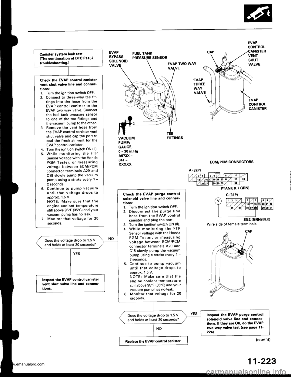
Canbter system leak test
{The continuation of DTC P1457
trouble3hootin9.)
Chock the EVAP control canistervent shut valve line and connoc'
tonS:1. Turn the ignition switch OFF
2. Connect to three'way tee fit_
tings into the hose from the
EVAP control canister to the
EVAP two way valve. Connect
the fuel tank pressure sensor
to one of the tee fittings and
the vacuum PumP to the other'
3. Remove the vent hose from
the EVAP control canister vent
shut valve and cap the Pon to
seal the fresh air vent Ior the
EVAP control canister.4. Turn the ignition switch ON (ll).
5. While monitoring the FTP
Sensor voltage with the Honda
PGM Tester, or measurangvoltage between ECM/PCM
connector terminals A29 and
C18 slowly PumP the vacuumpump using a stroke every 1 -
2 seconds.6. Continue to PumP vacuum
until that voltage droPs to
approx. 1.5 V.NOTE: Make sure that the
engine coolant temPeraturestillabove 95'F (35'Cland Yourvacuum PumP has no leak
7. Monitor that voltage for 20
seconds.
Check the EVAP Pu.ge control
solenoid valve line and connec-
tions:1. Turn the ignition switch OFF.
2. Disconnect the Purge lane
hose from the EVAP control
canister and Plug the Port3. Turn the ignition switch ON (lli.
4. While monitoring the FTP
Sensor voltage with the Honda
PGM Tester, or measuringvoltage between ECM/PCM
connector terminals A29 and
Cl8 slowly PumP the vacuumpump using a stroke every 1 -
2 seconds.5. Continue to pump vacuum
until that voltage droPs to
approx. 1-5 V.NOTE: Make sure that the
engine coolant temPeraturestill above 95'F (35"C) and Yourvacuum pump has no leak-
6. Monitor that voltage tor 20
seconds.
Doesthe voltage drop to 1.5 V
and holds at least 20 seconds?
lGp€ct the EVAP control cani3tel
vent 3hut valvo line and connec_
tion5.
Inlpect tho EVAP Putge control
solenoid valvo line and connec'
tion3. It th6y lro OK, do the EVAP
two way valve te3t (seo page 11-
2211.
Does the voltage drop to 1.5 V
and holds at least 20 seconds?
Reolace the EVAP conirol canister.
EVAPBYPASSSOLENOIDVALVE
FUEL TANK
EVAPCONTROL
VENTSHUTVALVE
EVAPCONTROLCANISTER
SENSOR
EVAP TWO WAYVALVE
EVAPTHREE
VALVE
ttrrL
ta
VACUUMPUMP/GAUGE,0 - 30 in.HgA973X -
041 -
XXXXX
FITTINGS
ECM/PCM CONNECTORS
A {32P)
PTANK ILT GRN)
c (31Pt
SG2 {GRN/BLK)
Wire side of female terminals
{cont'd)
11-223
www.emanualpro.com
Page 519 of 1395

Description
General Operation
The Automatic transmission is a 3-element torque converter and triple-shaft electronically controlled unit which provides 4
speeds forward and 1 reverse speed The unit is positioned in line with the engine'
There are two tvoes of automatic transmission on CR-V; the four-wheel drive (4WD) model ('97 - 00)' and the front-wheel
drive (2WD) model ('98 - 00).
Toroue Converter, G€ars, and Clutches
The torque converter consists of a pump. turbine. and stator assembly in a single unit. The torque converter is connected to
the engine crankshatt. These parts turn together as a unit as the engine turns. Around the outside of the torque converter is
a ring gear which meshes with the starter pinion when the engine is started. The torque converter assembly serves as a fly-
wheel while transmitting power to the transmission mainshaft.
The transmission has three parallel shafts: the mainshaft. the countershaft, and the sub-shaft. The mainshaft is in line with
the engine crankshaft. The mainshaft includes the 1st, 2nd. and 4th clutches, and gears lor 3rd,2nd,4th. reverse and 1st
(3rd gear is integral with the mainshaft, while reverse gear is integral with the 4th gear). The countershaft includes the 3rd
clutch and gears for 3rd,2nd, 4th, reverse, 1st, and park. Reverse and 4th gears can be locked to the countershaft at its cen-
ter, providing 4th gear or reverse, depending on which way the selector is moved. The sub-shaft includes the lst-hold
clutch and gears for lst and 4th.
The gears on the mainshaft are in constant mesh with those on the countershaft and sub-shaft. When certain combinations
of gears are engaged by the ctutches, power is transmitted from the mainshaft to the countershaft to provide E, D!, tr, tr,
and E position ('97 - 98 models). and E. E, E, and E position ('99 - 00 models)'
Electlonic Control
The electronic controt system consists of the Powenrain Control Module (PCM), sensors, a linear solenoid, and four
solenoid valves. Shifting and lock-up are electronically controlled for comfortable driving under all conditions. The PCM is
located below the dashboard, under the kick panel on the passenger's side.
Hydraulic Control
The valve bodies include the main valve body, the secondary valve body, the regulator valve body, the servo body, and
the lock up valve body. They are bolted to the torque converter housing. The main valve body contains the manual valve,
the 1-2 shift valve, the 2nd orifice control valve. the CPB {Clutch Pressure Back-up) valve, the modulator valve, the servo
control valve. the relief valve, and ATF pump gears. The secondary valve body contains the 2-3 shift valve, the 3-4 shift
valve, the 3,4 orifice control valve. the 4th exhaust valve and the CPC (Clutch Pressure Control) valve. The regulator valve
bodv contains the pressure regulator valve, the torque converter check valve, the cooler relief valve, and the lock-up con-
trol valve. The servo body contains the servo valve which is integrated with the reverse shift tork, and the accumulators
The lock-up valve body contains the lock-up shift valve and the lock-up timing valve. The linear solenoid and the shift con-
trol solenoid valve Ay'B are bolted to the outside of the transmission housing, and the lock-up control solenoid valve Ay'B is
bolted to the outside of the torque converter housing. Fluid trom the regulator passes through the manual valve to the
various control valves. The clutches receive fluid from their respective feed pipes or internal hydraulic circuit
ShiftControl Mechanism
input from various sensors located throughout the vehicle determines which shift control solenoid valve the PCM will acti-
vate. Activating a shift control solenoid valve changes modulator pressure, causing a shift valve to move. This pressurizes
a line to one of the clutches. engaging that clutch and its corresponding gear. The shift control solenoid valves A and B are
controlled by the PCM.
Lock-up Mechanism
tn E! position (,97 - 98 modets) and in E position ('99 - O0 models), in 3rd and 4th, and in Del position in 3rd ('97 - 98
models) and in El position with Over,Drive (O/D) is OFF (by pressing rhe O/D switchl in 3rd ('99 - 00 models), pressurized
fluid is drained from the back of the torque converter through a fluid passage, causing the lock-up piston to be held
against the torque converter cover, As this takes place, the mainshaft rotates at the same speed as the engine crankshaft.
Together with hydraulic control, the PcM optimizes the timing of the lock-up mechanism The lock-up valves control the
range of lock-up according to lock-up control solenoid valves A and B, and the linear solenoid. When lock-up control
solenoid valves A and B activate, the modulator pressure changes. The lock-up control solenoid valves A and B and the
linear solenoid are controlled by the PCM.
{cont'd)
14-3
www.emanualpro.com
Page 520 of 1395
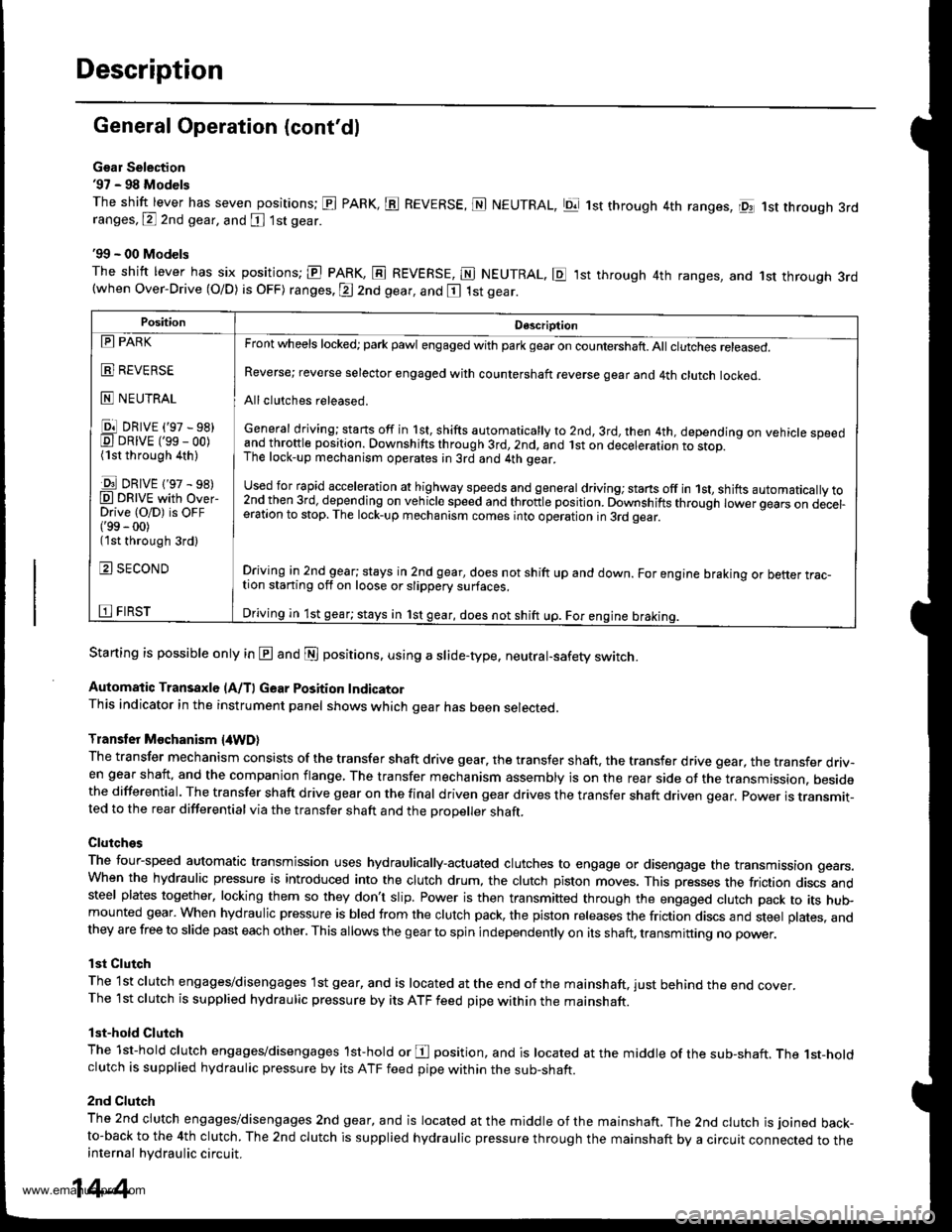
Description
General Operation (cont'dl
Gsar Selection'97 - 98 Models
The shift lever has seven positions; El PARK, ts REVERSE, N NEUTRAL, Ell 1st through 4th ranges, lpq 1st th.ough 3rdranges, P 2nd gear, and [ 1st gear
'99 - 00 Models
The shitt lever has six positions; El PARK, E REVERSE, E NEUTRAL. E ,lst through 4th ranges, and 1st through 3rd(when Over-Drive (O/D) is OFF) ranges. @ 2nd gear, and E 1st gear.
Starting is possible only in @ and @ positions. using a slide-type. neutral-safety switch.
Automatic Transaxle (A/T) Gear Position IndicatorThis indicator in the instrument panel shows which gear has been selected.
Transler Mochanism {4WD}
The transfer mechanism consists of the transfer shaft drive gear. the transfer shaft. the transfer drive gear, the transfer driv-en gear shaft, and the companion flange, The transfer mechanism assembly is on the rear side ot the transmission. besidethe differential. The transfer shaft drive gear on the final driven gear drives the transfer shaft driven qear. power is transmit-ted to the rear differential via the transfer shaft and the Drooeller shaft.
Clutches
The four-speed automatic transmission uses hydraulically-actuated clutches to engage or disengage the transmission gears.When the hydraulic pressure is introduced into the clutch drum, the clutch piston moves. This presses the friction discs andsteel plates together, locking them so they don't slip. Power is then transmifted through the engaged clutch pack to its hu$mounted gear. When hydraulic pressure is bled from the clutch pack, the piston releases the friction discs and steel plates, andthey are free to slide past each other. This allows the gearto spin independently on its shaft, transmitting no power.
lst Clutch
The 1st clutch engages/disengages lst gear, and is located at the end ofthe mainshaft, just behind the end cover.The 1st clutch is supplied hydraulic pressure by its ATF feed pipe within the mainshaft.
lst-hold Clutch
The 1st-hold clutch engages/disengages 1st-hold or E position, and is located at the middle of the sub-shaft. The 1st-holdclutch is supplied hydraulic pressure by its ATF feed pipe within the sub-shaft.
2nd Clutch
The znd ciutch engages/disengages 2nd gear, and is located at the middle of the mainshaft. The 2nd clutch is joined back-to-back to the 4th clutch. The 2nd clutch is supplied hydraulic pressure through the mainshaft by a circuit connected to theinternal hydraulic circuit.
PositionDescription
Reverse; reverse selector engaged with countershaft reverse gear and 4th clutch locked.
Allclutches released.
General driving; starts off in 1st, shifts automatically to 2nd, 3rd, then 4th, depending on vehicle speedand throftle position. Downshifts through 3rd,2nd, and lst on deceleration to stop.The lock-up mechanism operates;n 3rd and 4th gear.
used for rapid €cceleration at highway speeds and general driving; stans off in 1st, shifts automatically to2nd_then 3rd, dejending on vehicle speed and throttle position. Downshifts through lower gears on decel-eration to stop. The lock-up mechanism comes into operation in 3rd gear.
Driving in 2nd_gear; stays in 2nd gear, does not shift up and down. For engine braking or better trac_tion starting off on loose or slippery surfaces.
Driving in 1st gear; stays in 1st gear, does not shift up. For engine braking.
tll PARK
t!!l l|EvEn>E
E NEUTRAL
Ell DRrvE ('97 - sB)E DRrvE ('ss - oo)(1st through 4th )
E DRrvE {'97 - s8)O DRTVE with over-Drive (O/D) is OFF('99 - 00)(1st through 3rd)
E SECOND
E FIRST
14-4
www.emanualpro.com
Page 530 of 1395
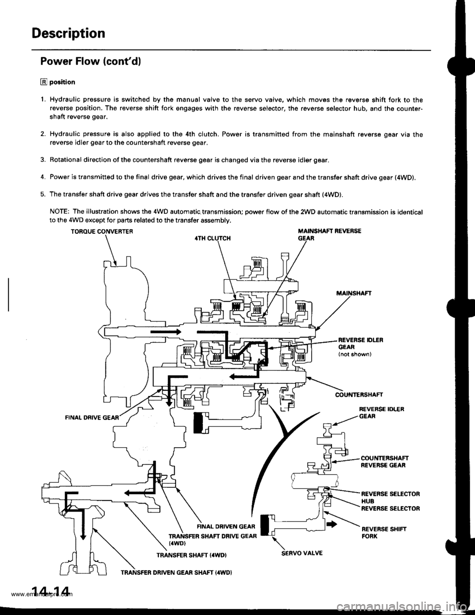
Description
Power Flow (cont'dl
E position
1. Hydraulic pressure is switched by the manual valve to the servo valve, which movss the reverse shift fork to the
reverse position, The reverse shift fork engages with the reverse selector, the reverse selector hub, and the counter-
shaft reverse gear.
2. Hydraulic pressure is also applied to the 4th clutch. Power is transmitted from the mainshaft reverse gear via the
reverse idler gear to the countershaft reverse gear.
3. Rotational direction ofthe countershaft reverse gear ischanged viathe reverse idlergear.
4. Power is transmitted to the final drivegear,which drivesthefinal d riven gear a nd the transfer shaft drive gesr (4WD).
5. The transfer shaft drive gear drives the transfer shaft and the transfer driven gear shaft (4WD).
NOTE: The illustration shows the 4WD automatic.transmission; power flow of the 2wD automatic transmission is identical
to the 4WD except for parts related to the transfer assembly.
TOROUE CONVERTERMAINSHAFT REVERSE
COUNTERSHAFT
FINAL ORIVE
REVERSE IDLERGEAR
COUNTERSHAFTREVERSE GEAR
REVERSE SEITCTORHUBREVERSE SELECTOR
REVEBSC SHIFTFORK
FINAL OBIVEN GEAR
TRANSFER SHAFT DRIVE GEAR{4WD)
TRANSFER SHAFT {4WD)SERVO VAI-VE
14-14
TRANSFER DRIVEN GEAR SHAFT I4WD}
www.emanualpro.com
Page 534 of 1395
Description
Electronic Control System (cont'dl
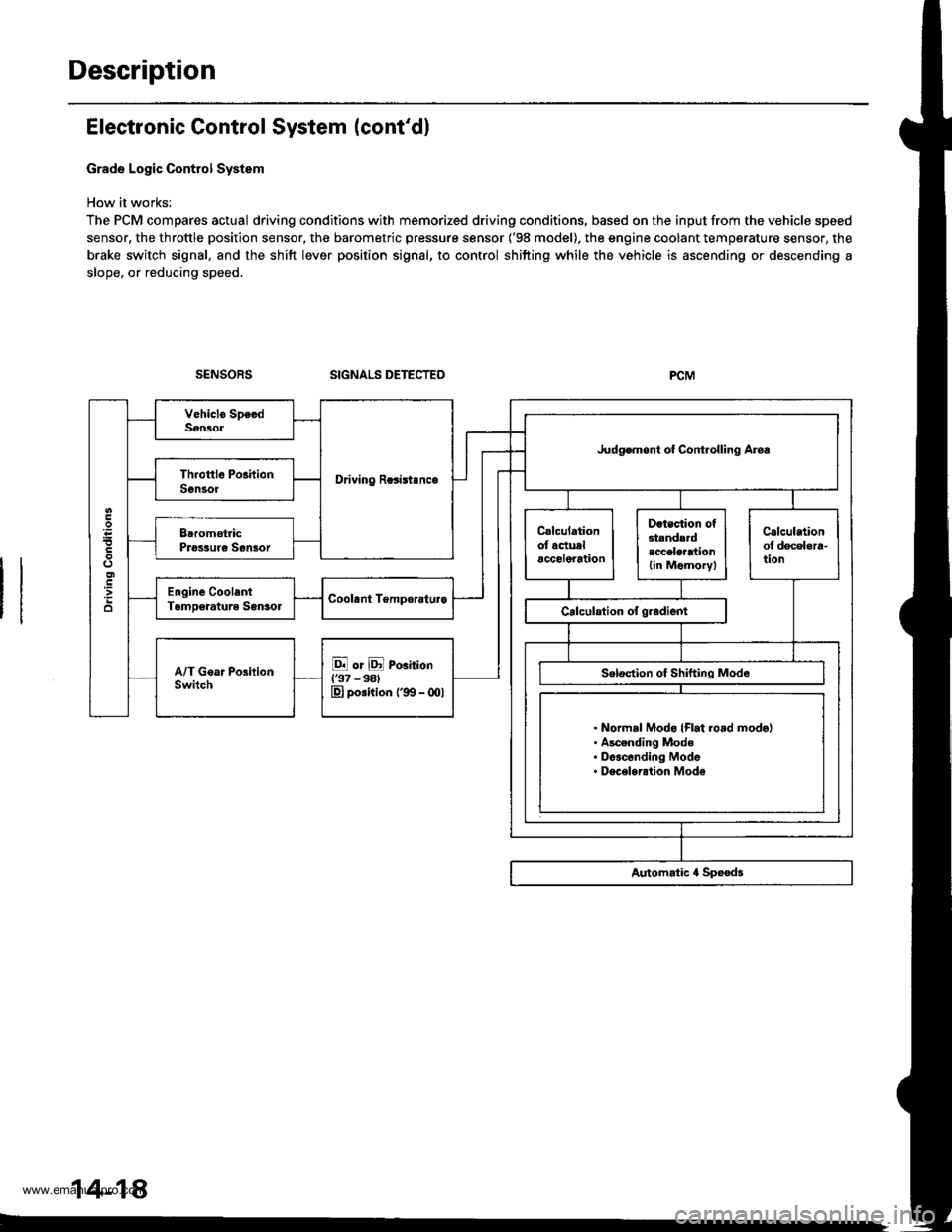
Grade Logic Control System
How it works:
The PCM compares actual driving conditions with memorized driving conditions, based on the input from the vehicle speed
sensor, the throttle position sensor, the barometric pressure sensor ('98 model). the engine coolant temperature sensor, the
brake switch signal, and the shift lever position signal, to control shifting while the vehicle is ascending or descending a
slope, or reducing speed.
SIGNALS DETECTED
Driving Rcsisl.nce
Judgemont ot Controlling Aroa
. Normal Modo {Flrt ro.d mode}. Ascending Mode. Deacending Mode. Deceleration Mode
14-14
www.emanualpro.com