Component locations HONDA CR-V 1999 RD1-RD3 / 1.G Owner's Guide
[x] Cancel search | Manufacturer: HONDA, Model Year: 1999, Model line: CR-V, Model: HONDA CR-V 1999 RD1-RD3 / 1.GPages: 1395, PDF Size: 35.62 MB
Page 1021 of 1395
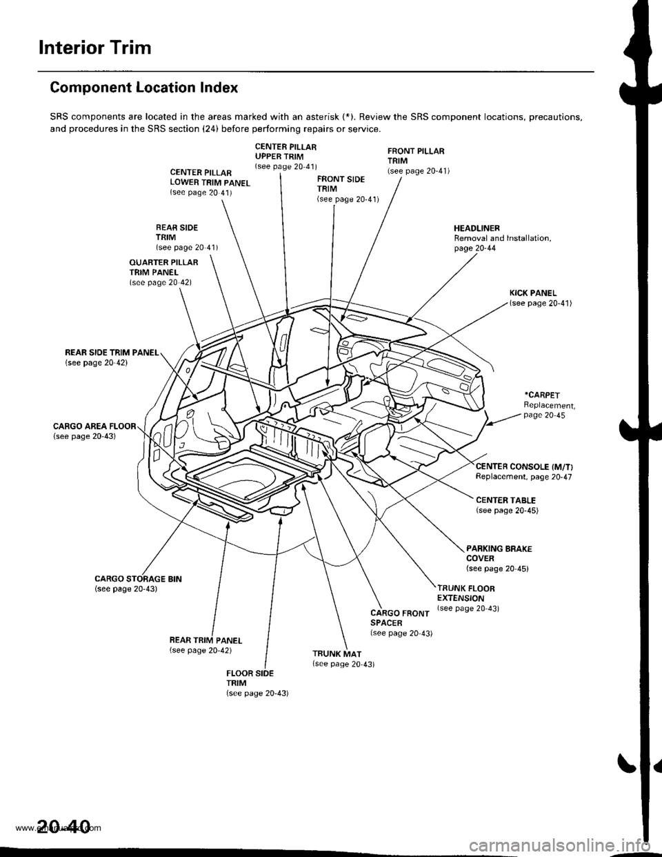
lnterior Trim
20-40
CARGO FRONTSPACER(see page 20 43)
FRONT PILLARTRIM(see page 20-41)
TRUNK FLOOREXTENSION(see page 20 43)
HEADLINERRemoval and lnstallation,page 20-44
Component Location Index
SRS components are located in the areas marked with an asterisk (*). Review the SRS component locations, precautions,
and procedures in the SRS section (24) before performing repairs or service.
CENTER PILLARUPPER TRIM(see page 20 41)CENTER PILLARLOWER TRIM PANEL(see page 20 41)
FRONT SIDETRIM(see page 20-41)
BEAR SIDETEIM(see page 20'41)
OUARTER PILLARTRIM PANEL(see page 20 42)
*CARPET
Replacement,page 20 45
CENTER CONSOLE IM/T}Replacement, page 20-47
CENTEN TABLE(see page 20-45)
PARKING BRAKECOVER(see page 20-45)
TRIM
www.emanualpro.com
Page 1026 of 1395
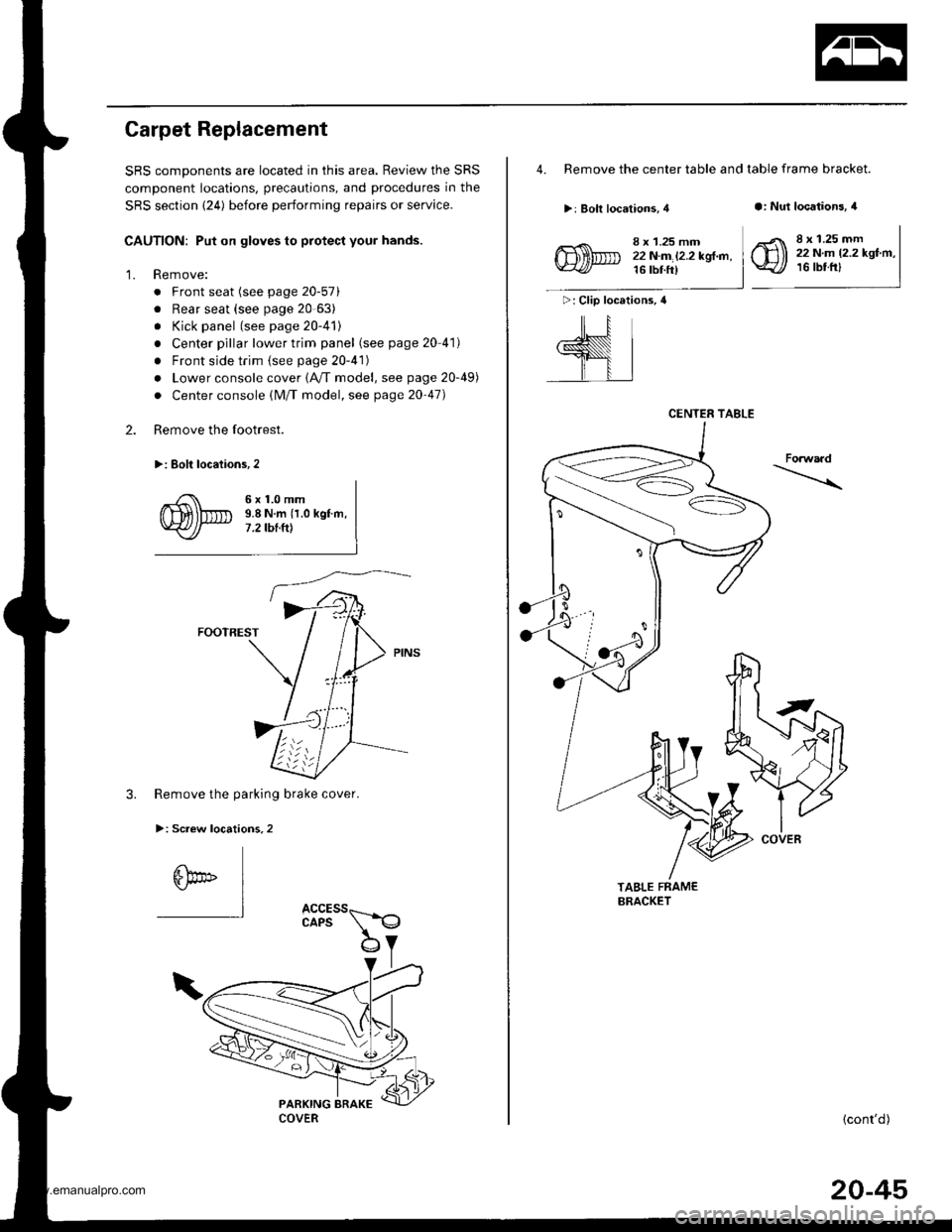
Carpet Replacement
SRS comDonents are located in this area. Review the SRS
component locations, precautions, and procedures in the
SRS section {24) before performing repairs or service.
CAUTION: Put on gloves to protect your hands.
Remove:
. Front seat (see page 20-571
. Rear seat (see page 20 63)
. Kick panel (see page 20-41)
. Center pillar lower trim panel (see page 20 41)
. Front side trim {see page 20-41)
. Lower console cover 1A,/T model, see page 20-49)
. Center console (lM/T model, see page 2o-47)
Remove the footrest.
>: Eolt locaiions,2
2.
'1.
6x1.0mm9.8 N.m {1.0 kgf.m,7 .2 tbt.ttt
FOOTREST
3. Remove the parking brake cover.
>: Screw locations,2
6bo" I"l
4. Remove the center table and table frame bracket.
>: Bolt locations, 4a: Nut locations, 4
>: Clip locations, 4
ill
,l
8 x 1.25 mm22N.m l2.2kgl.n,16 tbt ft)
8 x 1.25 mm22 N.m 12.2 kgf.m,16 tbtfrl
Forwaad
TABLE FRAMEBRACKET
{cont'd)
CENTER TABLE
COVER
20-45
www.emanualpro.com
Page 1029 of 1395
Dashboard
SRS components are located in this area. Review the SRS
component locations, precautions, and procedures in the
SRS section (24) before performing repairs or service.
GAUTION:
. When prying with a tlat-tip screwdriver, wrap h withproteqtive tape, and apply protective tape around the
relat€d parts, to prevent damage,
. Put on glovgs to protect your hands.
NOTE: Take care not to scratch the dashboard and relatedpans.
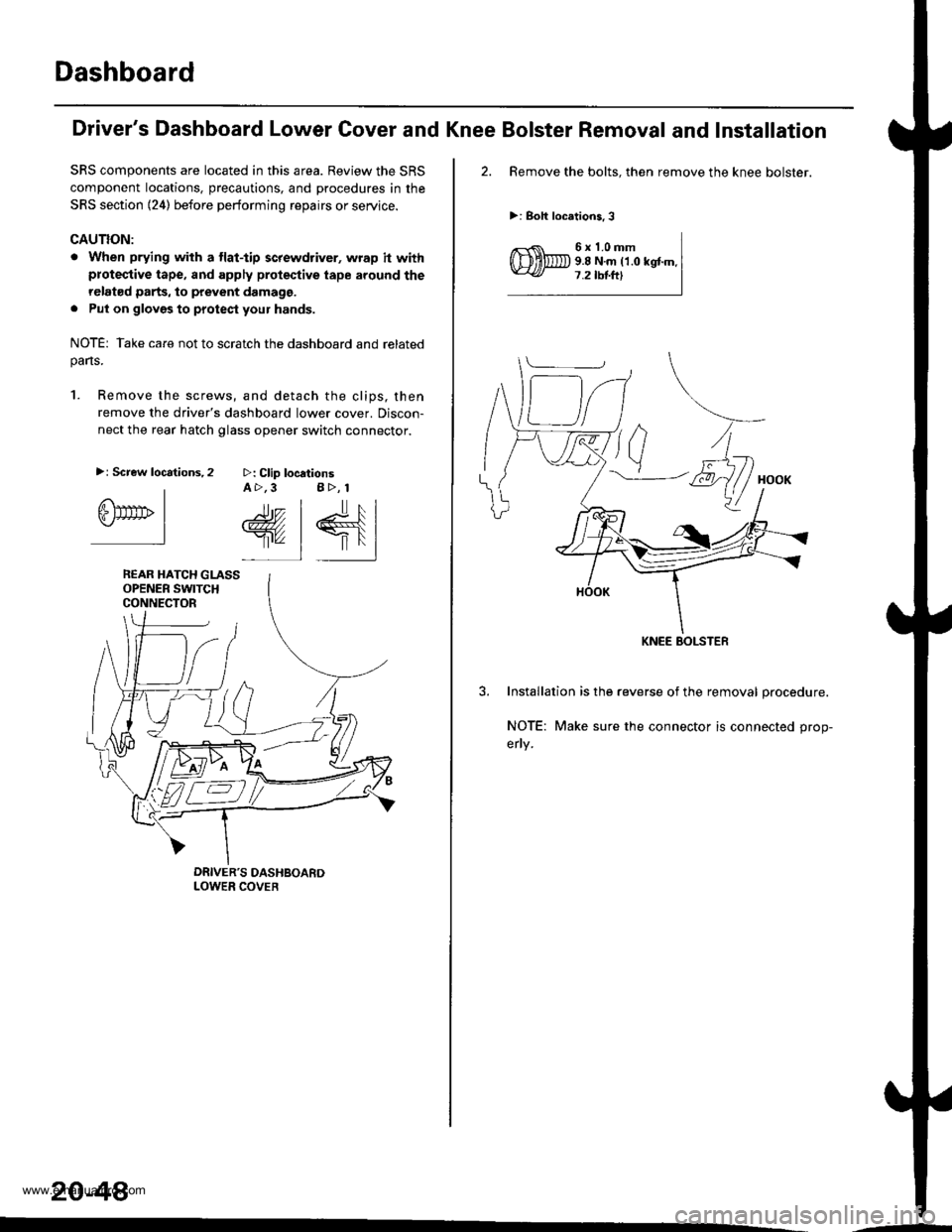
1. Remove the screws, and detach the clips, then
remove the driver's dashboard lower cover. Discon-
nect the rear hatch glass opener switch connector.
>: Clip locationsA >,3 B>, 1
rr.- | lr, l
@, | €{lr'" 1 |'l
>: Screw locations,2
IGlTtrrrb I.-l
REAR HATCH GLASSOPENER SWITCHCONNECTOR
20-48
'-
Driver's Dashboard Lower Cover and Knee Bolster Removal and Installation
2. Remove the bolts. then remove the knee bolster.
>: Boh locations,3
6x1.0mm9.8 N.m ('1.0 kgtm.7.2 tbtftl
3. Installation is the reverse of the removal procedure.
NOTE: Make sure the connector is connected prop-
erly.
KNEE BOLSTEF
www.emanualpro.com
Page 1031 of 1395
Dashboard
Center Dashboard Lower Gover
Removal and Installation
SRS components are located in this area. Review the SRS
component locations, precautions, and procedures in the
SRS section {24) before performing repairs or service
CAUTION:
. Wh€n prying with a flat-tip screwdrivet, wrap it with
protective tap€, and apply proteclive tape around the
rslated parts to prevenl damage.
. Put on glovgs to protect your hands.
NOTE: Take care not to scratch the dashboard and related
oarts.
1. Remove:
. Driver's dashboard lower cover (see page 20-48)
. Glove box (see page 20-49)
. Center pocket (AVT model. see page 20-49)
. Center console (M/f model, see page 20-41l,
. Center upper pocket (M/T model, see page 2O-47J
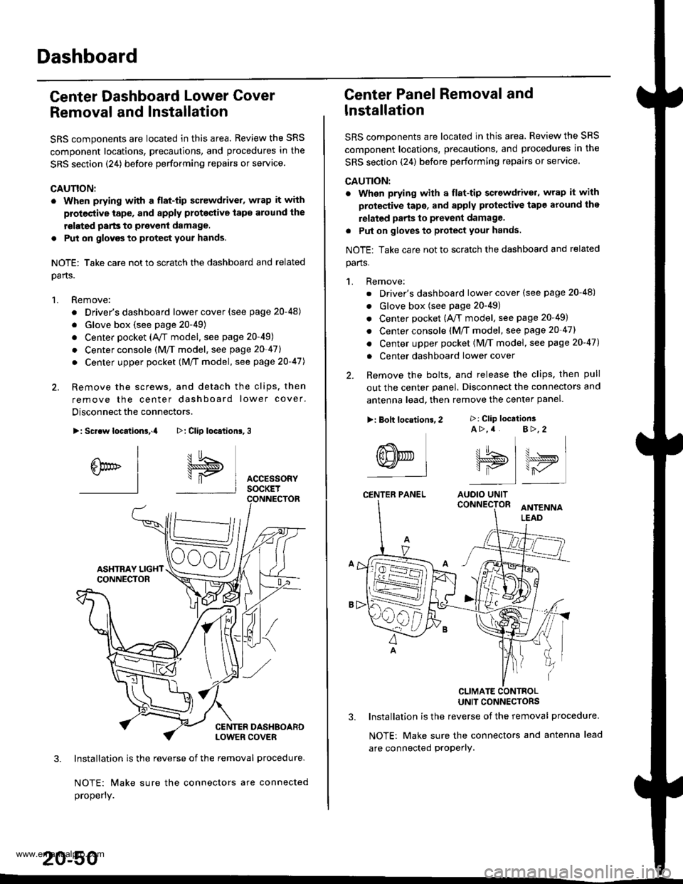
2. Remove the screws, and detach the clips. then
remove the center dashboard lower cover.
Disconnect the connectors.
>: Screw locationa,.a
I
6br" I-l
3. Installation is the reverse of the removal procedure-
NOTE: Make sure the connectors are connected
properly.
20-50
>: Clip loc.tion6,3
I5
\"P I AccEssoRyI socKET
Center Panel Removal and
lnstallation
SRS components are located in this area. Review the SRS
comDonent locations, precautions, and procedures in the
SRS section (24) before performing repairs or servace.
CAUTION:
. When prying with a flat-tip screwdriver, wrap it with
protective tape, and apply protective tape around the
relatgd parts to prevent damage.
. Put on gloves to protect your hands.
NOTE: Take care not to scratch the dashboard and related
parts.
1. Remove:
. Driver's dashboard lower cover (see page 20-48)
. Glove box (see page 20-49)
. Center pocket (A,/T model, see page 20-49)
. Center console (M/T model, see page 20-47)
. Center upper pocket {M/T model, see page 20-47)
. Center dashboard lower cover
2. Remove the bolts, and release the clips. then pull
out the center panel. Disconnect the connectors and
antenna lead. then remove the center panel.
CLIMATE CONTBOLUNIT CONNECTORS
3. Installation is the reverse of the removal procedure.
NOTE: Make sure the connectors and antenna lead
are connected proPerly.
>: Clip location3A >,4 B>,2
tt.t !^ t u . I\lJS>,, \>ryI is I r-,/'
AUOIO UNIT
>: Bolt locations,2
(8NED L-l
CENTER PANEL
www.emanualpro.com
Page 1034 of 1395
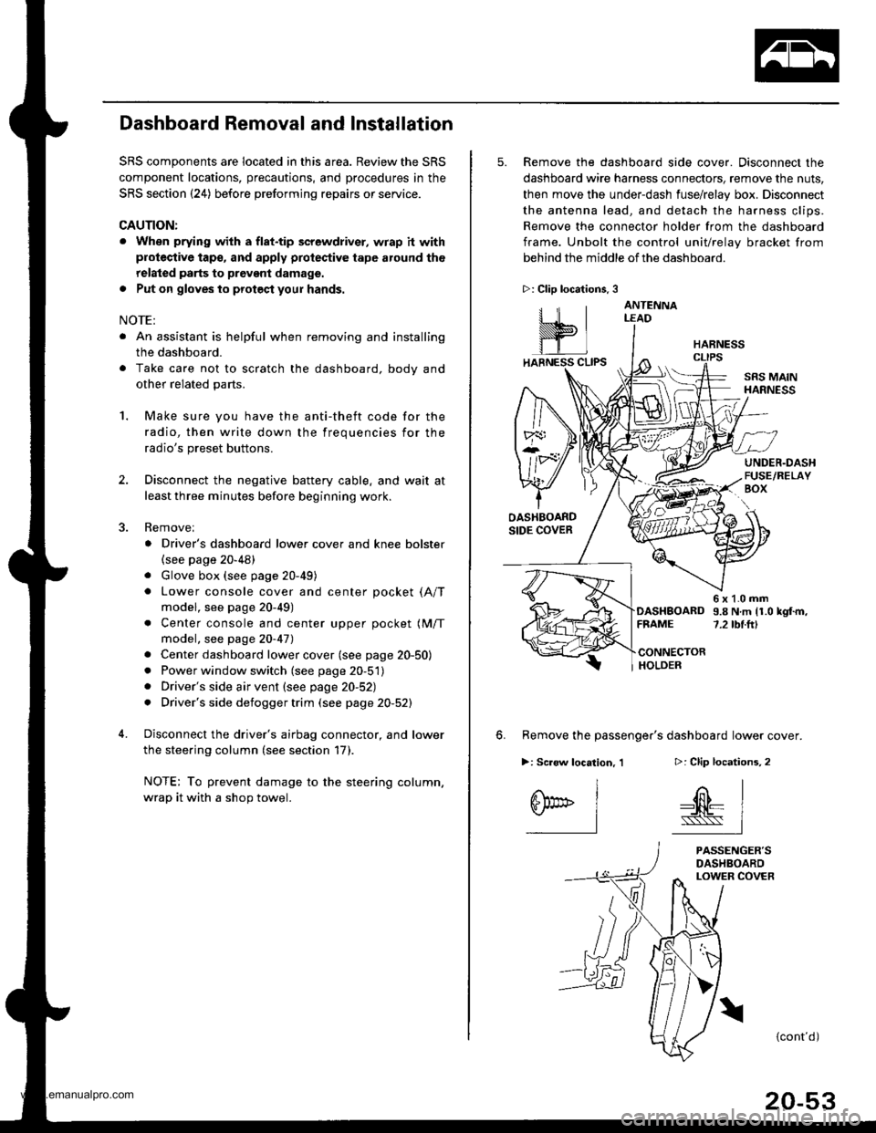
Dashboard Removal and Installation
SRS components are located in this area. Review the SRS
component locations, precautions, and procedures in the
SRS section {24) before preforming repairs or service.
CAUTION:
. When prying with a flat-tip screwdriver, wrap h withprotective tap€, and apply protective tape around the
related parts to prevgnt damage.
. Put on gloves to prot€ct your hands.
NOTE:
. An assistant is helpful when removing and installing
the dashboard.
. Take care not to scratch the dashboard, bodv and
other related parts.
1.Make sure you have the anti-theft code for the
radio, then write down the frequencies for the
radio's preset buttons.
Disconnect the negative battery cable. and wait at
least three minutes before beginning work.
Removei
a Driver's dashboard lower cover and knee bolster(see page 20-48)
. Glove box (see page 20-49)
. Lower console cover and center pocket (A/T
model, see page 20-49)
. Center console and center upper pocket (M/T
model, see page 20-47)
. Center dashboard lower cover (see page 20-50)
. Power window switch (see page 20-51)
. Driver's side air vent (see page 20-52)
. Driver's side defogger trim (see page 20-52)
Disconnect the driver's airbag connector, and lower
the steering column (see section 17)
NOTE: To prevent damage to the steering column,
wrap it with a shop towel.
2.
5. Remove the dashboard side cover. Disconnect the
dashboard wire harness connectors, remove the nuts,
then move the under-dash fuse/relay box. Disconnect
the antenna lead, and detach the harness clips.
Remove the connector holder from the dashboard
frame. Unbolt the control unit/relay bracket from
behind the middle of the dashboard.
HARNESS
6. Remove the passenger's dashboard lower cover.
D: Clip locations,
nl
-$t- Issj
I
ANTENNALEAD
>: Clip locations.
rttl
slllll
>: Scr€w location, 1
I
SF:oo I-l
SRS MAINHARNESS
UNDER.DASHFUSE/RELAYBOX
OASHBOARDSIDE COVER
6x1.0mm9.8Nm11.0kgf.m,7.2tbt.ftlDASHBOARDFFAME
CONNECTORHOLDER
PASSENGER'SDASHBOARDLOWER COVER
{cont'd)
www.emanualpro.com
Page 1094 of 1395
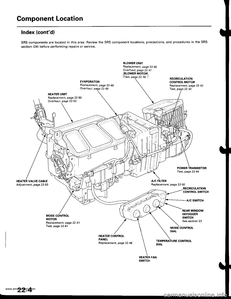
Component Location
lndex (cont'dl
SRS components are located in this area. Review the SRS component locations, precautions, and procedures in the SRS
section (24) before performing repairs or service.
BLOWER UNITReplacement, page 22-46Ovethaul, page 22 47
/alowen ruoronl
\Test, page 22-16 /
EVAPORATORFeplacement, page 22-48Overhaul, page 22,49
RECIRCULATIONCONTROL MOTORReplacement, page 22 42
HEATER UNITReplacement, page 22 50Overhaul, page 22 52
lest, pag.e 22 42
A/C FILIERReplacement. page 22-50VALVE CABLEAdjustment, page 22-53
RECIRCULATIONCONTROL SWITCH
a/c swtTcH
MODEMOTOR
REAR WINDOWDEFOGGERSwlTCHSee section 23Replacement, page 22-41Test, page 22-41MODE CONTROLDIAL
HEATER CONTROLPANELReplacement, page 22 46
swtTcH
22-4
CONTROL
www.emanualpro.com
Page 1096 of 1395
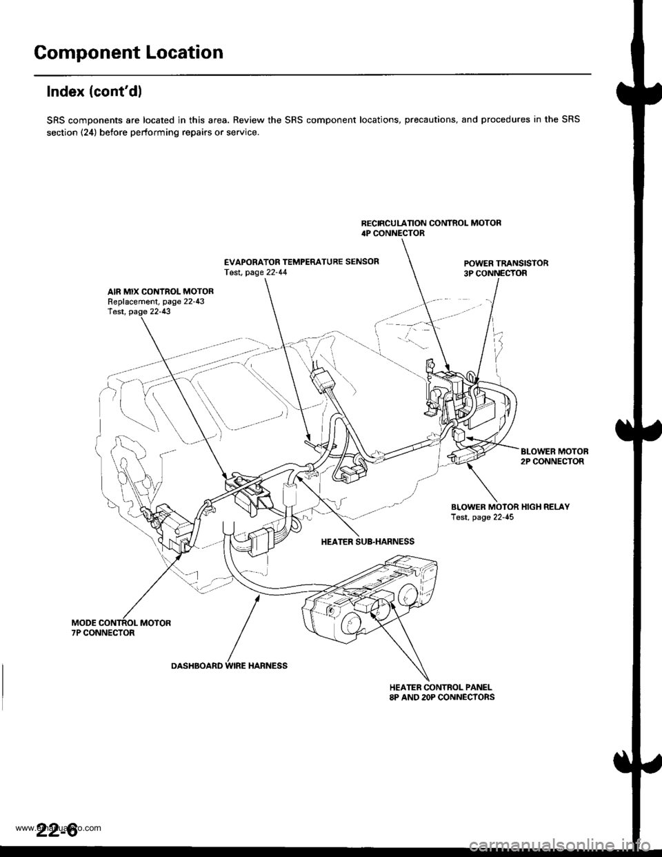
Component Location
Index (cont'dl
SRS components are located in this area. Review the SRS component locations, precautions, and procedures in the SRS
section (24) before performing repairs or service.
BECIRCULATION CONTROL MOTOR4P CONNECTOR
EVAPORATOR TEMPERATURE SENSORTesl, page 22-44POWER TRANSISTOR3P CONNECTOR
AIR MIX CONTROL MOTORReplacement, page 22-43lest, page 22-13
BLOWER MOTOB2P CONNECTOR
BLOWER MOTOR HIGH RELAYTest, page 22-45
HEATER SUB.HARNESS
7P CONNECTOR
DASHBOARD WIRE HARNESS
HEATER CONTROL PANEL8P AND 2OP CONNECYORS
22-6
www.emanualpro.com
Page 1140 of 1395
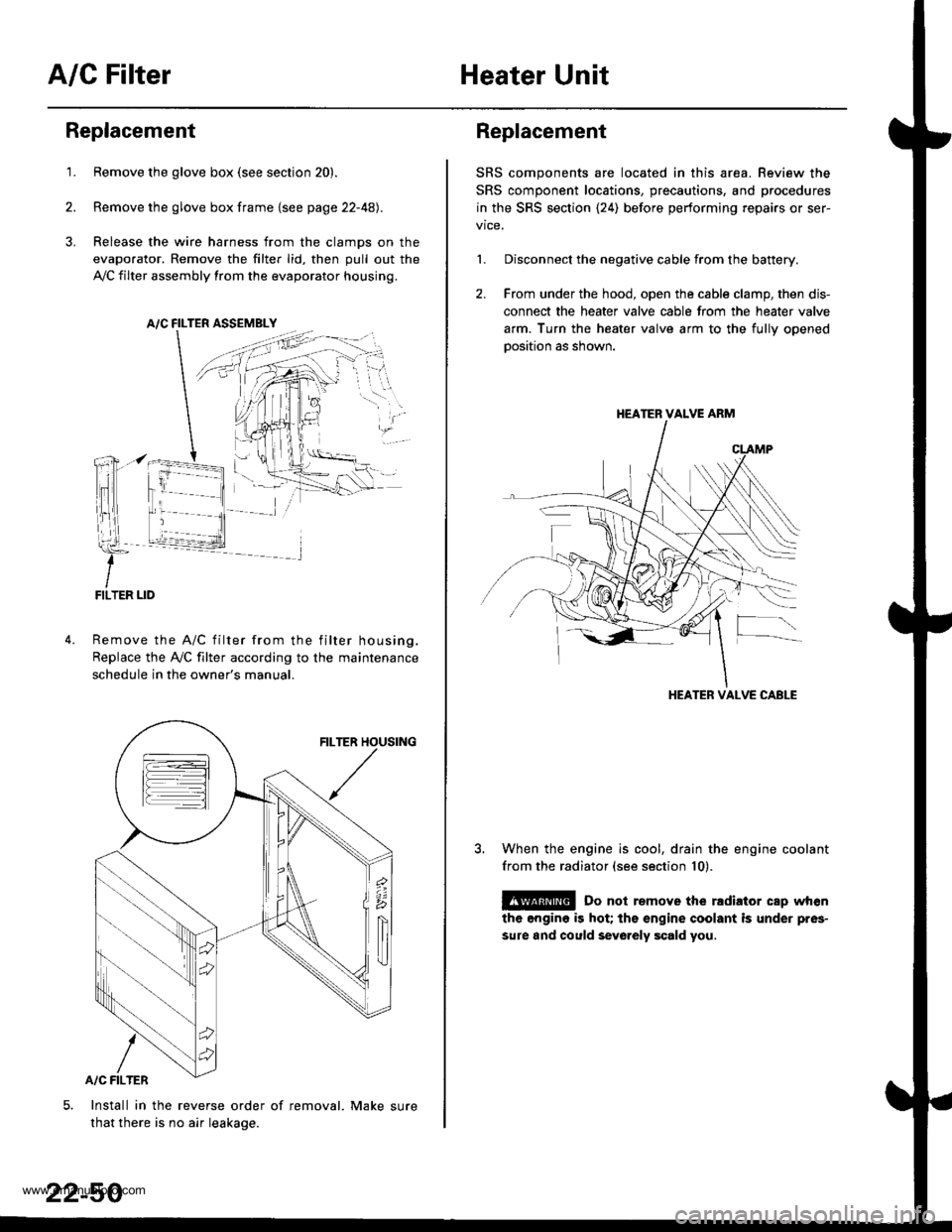
A/C FilterHeater Unit
Replacement
1.Remove the glove box (see section 20).
Remove the glove box frame {see page 22-4A).
Release the wire harness from the clamps on the
evaporator. Remove the filter lid, then pull out the
,VC filter assembly from the evaporator housing.
A/C FILTER ASSEMELY
Remove the A/C filter from the filter housing.
Replace the Ay'C filter according to the maintenance
schedule in the owner's manual.
Install in the reverse order of removal. Make sure
that there is no air leakage.
22-50
Replacement
SRS components are located in this area. Review the
SRS component locations, precautions, and procedures
in the SRS section {24) before performing repairs or ser-
1. Disconnect the negative cable from the battery.
2. From under the hood, open the cable clamp, then dis-
connect the heater valve cable from the heater valve
arm. Turn the heater valve arm to the fullv ooened
oosition as shown.
When the engine is cool, drain the engine coolant
from the radiator (see section 10).
@ Do not remove the rldiator cap when
the engine is hot; the engine coolant is under pres-
sure and could sevo.ely scald you.
HEATER VALVE ARM
HEATER VALVE CABLE
www.emanualpro.com
Page 1209 of 1395
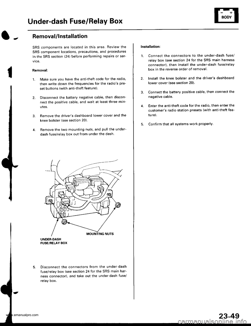
Under-dash Fuse/Relay Box
I
Removal/lnstallation
SRS components are located in this area. Review the
SRS component locations, precautions, and procedures
in the SRS section (241 before performing repairs or ser-
vice.
Removal:
1. Make sure you have the anti-theft code for the radio,
then write down the frequencies for the radio's pre-
set buttons (with anti-theft feature).
2. Disconnect the battery negative cable, then discon-
nect the positive cable, and wait at least three min-
utes.
3. Remove the driver's dashboard lower cover and the
knee bolster (see section 20).
4. Remove the two mounting nuts, and pull the under-
dash fuse/relay box out from under the dash
Disconnect the connectors from the under-dash
fuse/relay box (see section 24 for the SRS main har-
ness connector), and take out the under-dash fuse/
relay oox.
Installation:
1. Connect the connectors to the under-dash fuse/
relay box (see section 24 for the SRS main harness
connector), then install the under-dash lusehelay
box in the reverse order of removal.
2. lnstall the knee bolster and the driver's dashboard
lower cover (see section 20).
3. Connect the battery positive cable, then connect the
negative cable.
4. Enter the anti-theft code for the radio, then enter the
customer's radio station presets (with anti-thett fea-
ture).
5. Confirm that all systems work properly
23-49
www.emanualpro.com
Page 1214 of 1395
lgnition Switch
Test
SRS components are located in this area. Review the
SRS component locations, precautions, and procedures
in the SRS section {24} before performing repairs or ser
vtce.
L lMake sure you have the anti-theft code for the
radio, then write down the frequencies for theradio's preset buttons (wilh anti-theft feature).
2. Disconnect the battery negative cable.
3. Remove the driver's dashboard lower cover and the
knee bolster {see section 20).
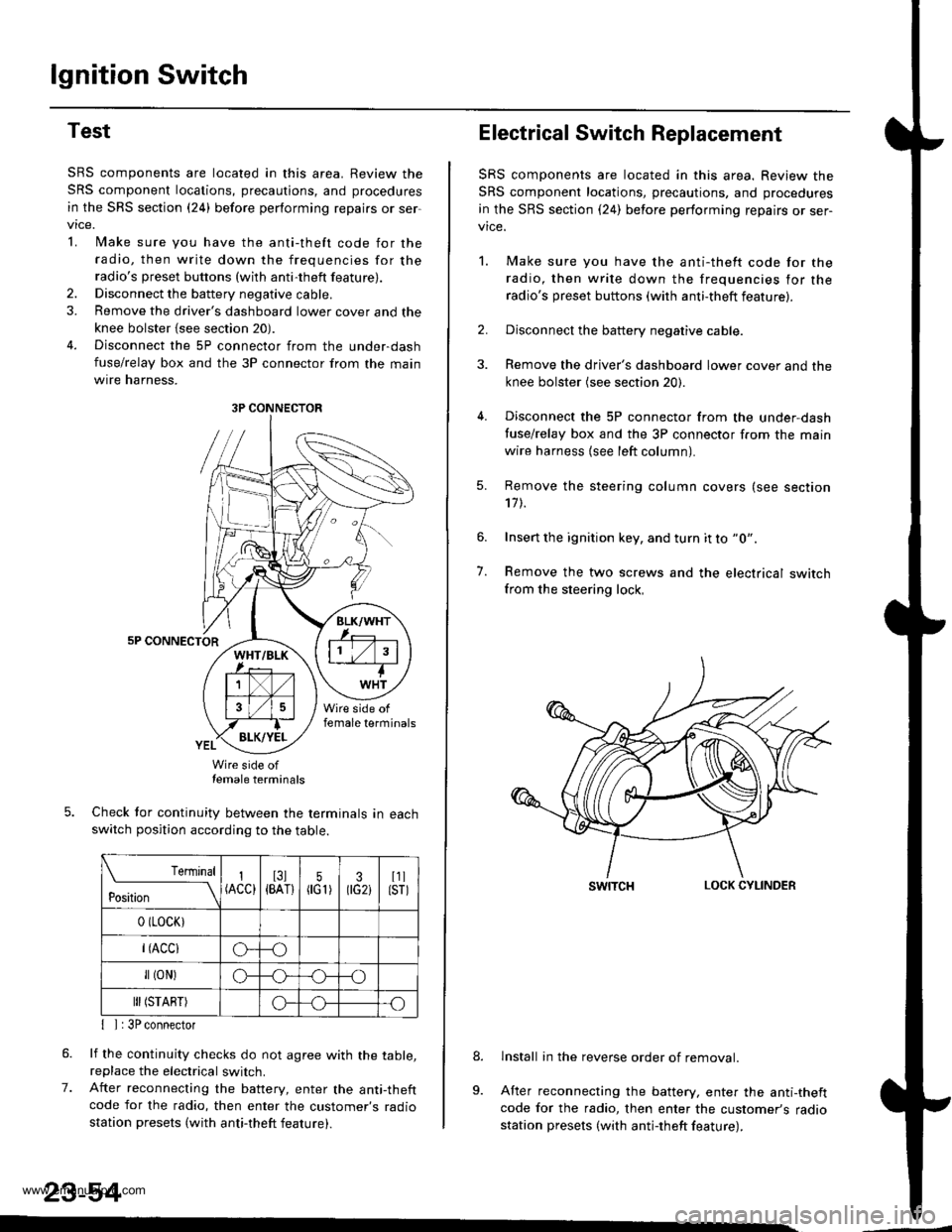
4. Disconnect the 5P connector from the under-dash
fuse/relay box and the 3P connector from the main
wtre narness,
5P CONNECTOR
Wire side oftemale terminals
Check tor continuity between the terminals in eachswitch position according to the table.
rernrnal
ros[ron \
I(ACC)I3l{BAT}5flG1)30G2iI1llsrl
0 (LocK)
r(Acclo--o
fl (oN)G_o
III (START)o--.o
7.
{ I | 3P connector
lf the continuity checks do not agree with the table,replace the electrical switch.
After reconnecting the battery, enter the anti-theftcode for the radio, then enter the customer's radio
station presets (with anti-theft feature).
23-54
3P CONNECTOR
Electrical Switch Replacement
SRS components are located in this area. Review the
SRS component locations, precautions, and procedures
in the SRS section {24) before performing repairs or ser-vice.
1. Make sure you have the anti-thett code for the
radio, then write down the frequencies for the
radio's preset buttons (with anti-theft feature).
2. Disconnect the battery negative cable.
3. Remove the driver's dashboard lower cover and the
knee bolster (see section 20).
4. Disconnect the 5P connector from the under,dash
tuse/relay box and the 3P connector f.om the main
wire harness {see left column).
7.
Remove the steering column covers (see section'17 t.
Insert the ignition key, and turn it to "0".
Remove the two screws and the electrical switchfrom the steering lock,
swrTcHLOCK CYLINDER
lnstall in the reverse order of removal.
After reconnecting the battery, enter the anti-theftcode for the radio, then enter the customer's radiostation presets (with antj-theft feature).
9.
www.emanualpro.com