air condition HONDA CR-V 1999 RD1-RD3 / 1.G Owner's Guide
[x] Cancel search | Manufacturer: HONDA, Model Year: 1999, Model line: CR-V, Model: HONDA CR-V 1999 RD1-RD3 / 1.GPages: 1395, PDF Size: 35.62 MB
Page 633 of 1395
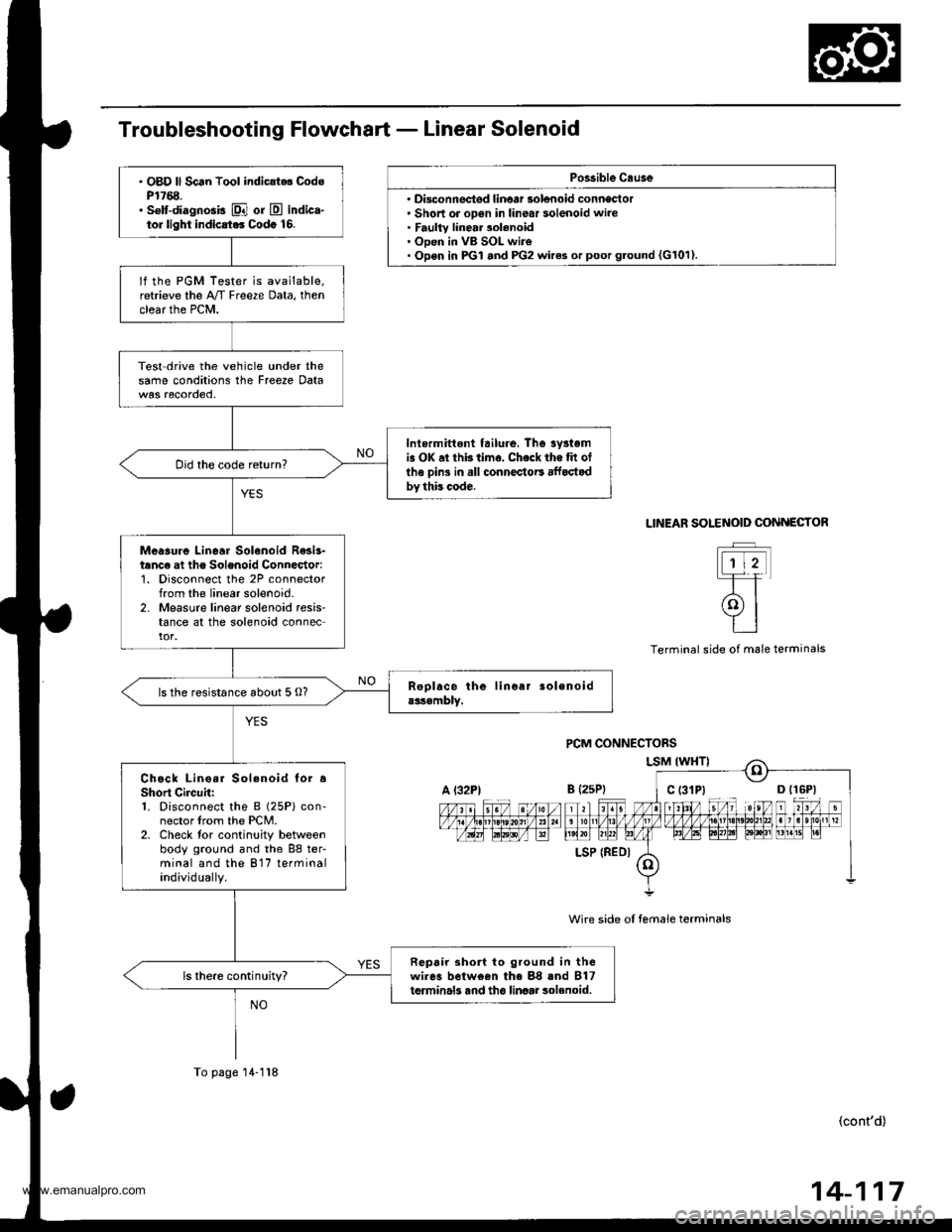
Po$ible Cau3e
' Disconnectsd linoar solenoid conneclol. Short or open in linear solenoid wire. Faulty linear 3olenoid. Open in VB SOL wire. Open in PGI and PG2 wires or poot g.ound {G101).
. OBD ll Scan Tool indic{t.. CodsP1768.. selt-diagnosis El or E indica-tor light indicrt.. Codo 16.
lf the PGM Tester is available.retrieve the A/T Freeze Data, thenclear the PCM.
Test drive the vehicle under thesame conditions the Freeze Data
Inlermittont tailure, The 3yrtomis OK at thb time. Check the tit otlhe oins in all connectoE affoctodby this code.
Did the code return?
Meaaure Linear Solenoid R€sis-tanc€ at the Solenoid Connector:1. Disconnect the 2P connectorfrom the linear solenoid-2. Measure linear solenoid resis-tance at the solenoid connector.
ls the resistance about 5 O?
Chock Lino.r Sol.noid to. aShort Circuh:1. Disconnect the B (25P) con-nector lrom the PCM.2. Check tor continuity betweenbody ground and the 88 ter-minal and the 817 terminalindividually.
Repair 3ho to ground in thewires belween the 88 rnd B17terminals and tho linaar 3olenoid.ls there continuity?
A l32PtB {2sP)
LSP (REDI
To page 14-118
SOLENOID COiINECTOR
t-rtt
(9l
tt
LINEAR
Terminal side ol male terminals
wire side oI temale terminals
(cont'd)
14-117
www.emanualpro.com
Page 635 of 1395
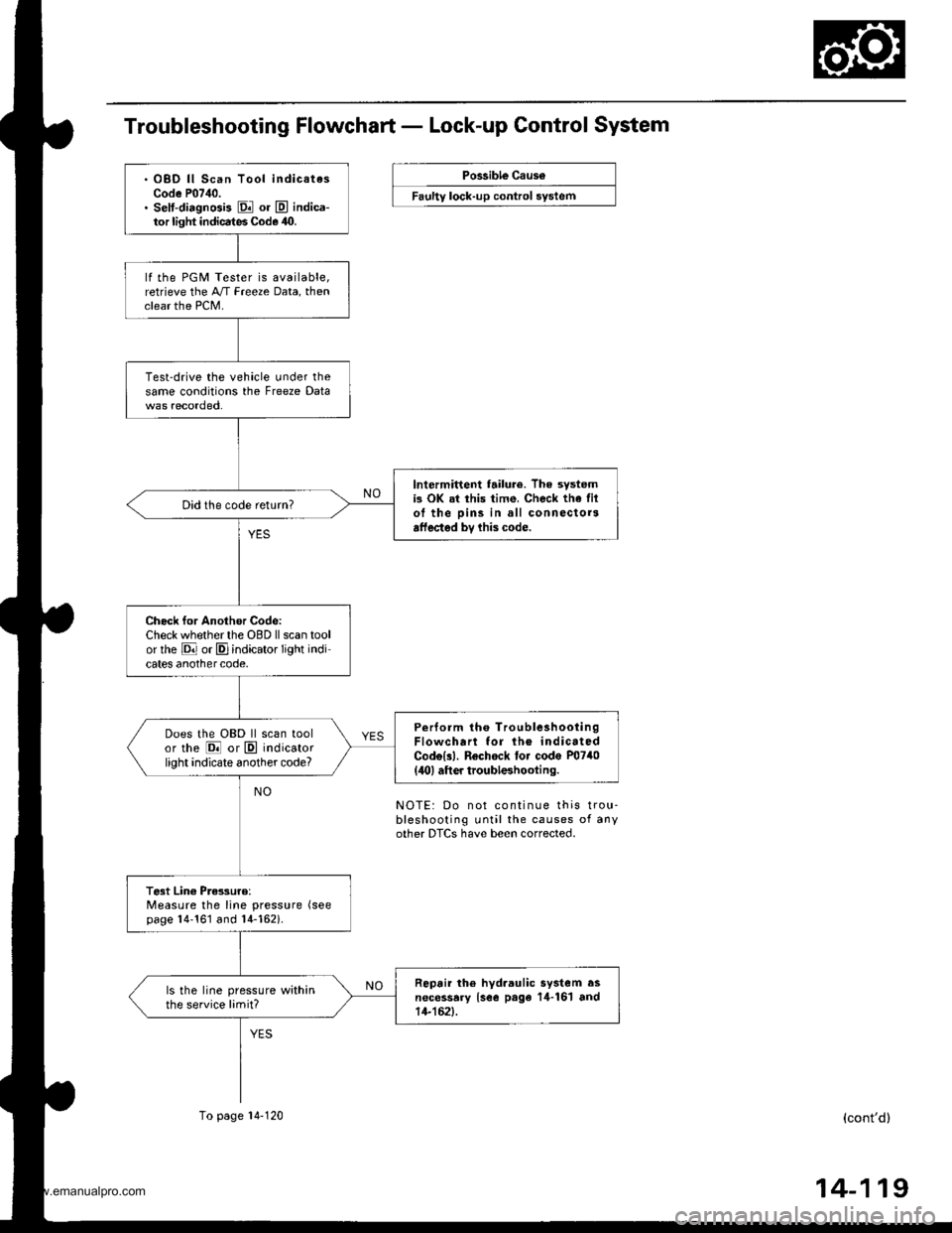
Troubleshooting Flowchart - Lock-up Control System
Possible Caus6
Faulty lock-up control system
. OBD ll Scan Tool indicatesCode P07,10.. selt-diagnGis El or E indica-tor light indicates Code 40.
lf the PGM Tester is available,retrieve the A/T Freeze Data, thenclear the PCM.
Test-drive the vehicle under thesame conditions the Freeze Data
lntermittent failur6. The systemis OK at this time, Check the filol the pins in all connectorsaffected bv lhis code.
Did the code return?
Check for Another Codc:Check whether the OBD ll scan toolor rhe E or E]indicator light indicates anothercode,
Perform tho TroubleshootingFlowchart for lh6 indicatedCodolll. Rechock tor code P0740(,lO) aft er troubleshooting.
Does the OBD ll scan toolor the @ or E indicatorlight indicate another code?
Test Lin€ Pres3uro:Measure the line pressure (see
page 14'161 and 14-162i.
Repair th6 hyd.aulic system asnecessary {see page 14-161 and14-152).
ls the line pressure withinthe service limit?
To page 14-120
NOTE: Do not continue this trou-bleshooting until the causes of anyother DTCS have been corrected.
(cont'd)
14-119
www.emanualpro.com
Page 637 of 1395
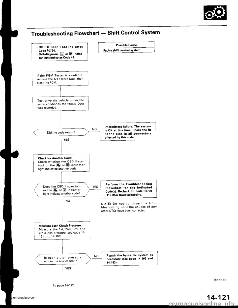
Troubleshooting Flowchart - Shift Control System
Possible Cause
Faultv shift control sYstem
NOTE: Do not continue thas trou
bleshooting until the causes of any
other DTCS have been corrected.
(cont'd)
14-121
. OBD ll Scan Tool indicates
Code P0730.. Self-diagnosis Jir or E indica-
tor light indicates Code 41.
lf the PGM Tester is available,
retrieve the AJ.I Freeze Data, then
clear the PCM.
Test-drive the vehicle under the
same conditions the Freeze Data
lntermittent failure. The system
is OK at this time. Ch€ck the fit
of the pins in all connectors
atfected by this code.
Did the code return?
Check for Another Code:
Check whether the OBD ll scan
tool or the l-Drl or E] indicator
light indicates another code.
Perlorm the TroubleshootingFlowchart for the indicaled
Codets). Recheck for code P0730
{411 6ft6r troubleshooting.
Does the OBD ll scan tool
or the Da or E indicatorlighl indicate another code?
Measure Each Clutch Pressure:
Measure the 1st, 2nd, 3rd, and
4th clutch Pressure (see Page 14
161 thru 14163).
Repair the hydraulic sYstem as
necessary (se€ page 14-162 and
14-163).
ls eac h clutch Pressurewithin the service limit?
To page 14-122
www.emanualpro.com
Page 658 of 1395

A/T Gear Position Indicator
1.
f nput Test -'97 - 98 Models
Remove the gauge assembly from the dashboard (see section 20). and disconnect the 14P connector from the gauge
assemblv (see section 23),
Inspect the connector and socket terminals to be sure they are all making good contact.
. lf the terminals are bent, loose, or corroded, repairthem as necessary, and recheck the system.. lf the terminals look OK, make the following input tests at the 14P connector.- lf I test indicates a problem, find and correct the cause, then recheck the system.- lf all the input tests prove OK, but the indicator is faulty. replace the printed circuit board,
GAUGE ASSEMBLY 14P CONNECTOR
Wire side of female terminals
CavityWirs
ColorTest ConditionTest: Desir€d ResultPossible Cause
{lf rosult is not obtainod)
YEL
lgnition switch ON (ll)Check for voltage to ground:
There should be battery voltage,
. Blown No. 25 (7.5 A) fuse in the
under-dash fuse/relay box. An open in the wire
RE D/BLKCombination light
switch ON and dash
lights brightness con-
trol dial on full bright
Check for voltage between No. 2
and No. 3 terminals;
There should be battery voltage.
Blown No. 47 (7.5 A) fuse in the
under-dash fuse/relay box
Faulty combination Iight switch
Faulty dash iight brightness
controller
An open in the wire
RED
4BLUShift lever in ECheck for continuity to ground:
There should be continuity.
NOTE: There should be no continu-
ity in any other shift lever position.
' Faulty Ay'T gear position switch. An open in the wireBRNShift lever in E
7YELShift lever in @
8BLKUnder all conditionsCheck for continuity to ground:
There should be continuity
. Poor ground {G401). An open in the wire
9GRN/BLK
lgnition switch ON {ll)
and shift lever in any
position except E
Check for voltage to ground:
There should be battery voltage
for two seconds after the ignition
switch is turned ON {ll), and less
than 1 V two seconds later,
' Faulty PCM. An open in the wire
10GRNShift lever in ECheck for continuity to ground:
There should be continuity.
NOTE: There should be no conti-
nuity in any other shift lever posi-
UOn.
. Faulty A,ff gear position switch. An open in the wire1'lREDShift lever in @
12WHTShift lever in E
BLVBLU
Shift lever in ENOTE: Do not push
the brake pedal.
14LT GRN
lgnition switch ON { ll)
and shift lever in any
position except E and
E
Check for voltage to ground:
There should be about 5 V.
. Faulty PCM. An open in the wire
14-142
www.emanualpro.com
Page 659 of 1395

L
Input Test -'99 - 00 Models
Remove the gauge assembly from the dashboard {see section 20), and disconnect the 14P connector from the gauge
assembly (see section 23).
Inspect the connector and socket terminals to be sure they are all making good contact.
a lf the terminals are bent. loose, or corroded. repair them as necessary. and recheck the system.
. lf the terminals look OK, make the following input tests at the 14P connector.- lf a test indicates a problem, find and correct the cause, then recheck the system.- lf all the input tests prove OK, but the indicator is faulty, replace the printed circuit board.
GAUGE ASSEMBLY 14P CONNECTOR
Wire side of female terminals
CavityWire
ColorTest ConditionTest: Desired ResuhPossible Caus6
{lf resutt is not obtainod)
1YEL
lgnition switch ON (ll)Check for voltage to ground:
There should be battery voltage.
. Blown No.25 (7.5 A) fuse in the
under-dash fuse/relay box. An open in the wire
2RE D/BLK
Combination light
switch ON and dash
lights brightness con-
trol dial on full bright
Check for voltage between No. 2
and No.3 terminals:
There should be battery voltage.
Blown No. 47 {7.5 A) fuse in the
under-dash fuse/relay box
Faulty combination light switch
Faulty dash light brightness
controller
An open in the wire
5RED
BRNShift lever in ECheck for continuity to ground:
There should be continuity.
NOTE: There should be no continu-
ity in any other shift lever position.
. Faulty A/T gear position switch. An open in the wire7YELShift lever in E
'10BLUShift lever in E
LT BLU
lgnition switch ON (ll),
shift lever in E. and
Over-Drive is OFF bypressing O/D switch.
Check for continuity to ground:
There should be continuity.
Faulty O/D switch
Faulty A/T gear position switch
Faulty PCM
An open in the wire
8BLKUnder all conditionsCheck for continuity to ground:
There should be continuity
. Poor ground (G401)
. An open in the wire
9a:FI\|/Et| ta
lgnition switch ON (ll)
and shift lever in any
position except E
Check for voltage to groundl
There should be battery voltage
for two seconds after the ignition
switch is turned ON (ll). and less
than 1 V two seconds later.
. Faulty PCM. An open in the wire
11REDShift lever in SCheck for continuity to ground:
There should be continuity.
NOTE: There should be no conti-
nuity in any other shift lever posi-
Iton.
. Faulty A/T gear position switch. An open in the wire12WHTShift lever in E
BLI(BLU
Shift lever in ENOTE: Do not push
the brake pedal.
14LT GRN
lgnition switch ON (ll)
and shift lever in any
position except E and
E
Check for voltage to groundl
There should be about 5 V,
. Faulty PCM. An open in the wire
14-143
www.emanualpro.com
Page 707 of 1395
1.Remove the control lever mounting bolt trom the
torque converter side of the torque converter hous-
ing. (4WD)
Remove the ATF feed pipes from the servo body,
secondary valve body, lock-up valve body, and main
valve body.
For '97 - 98 models:
Remove the two bolts securing the ATF strainer and
servo detent base, then remove the strainer and the
base.
For'99 - 00 models;
Remove the ATF strainer {one bolt).
4. For'97 - 98 models:
Remove the seven bolts securing the servo body,
then remove the servo body and separator plate'
For'99 - 00 models:
Remove the eight bolts securing the servo body,
then remove the servo body and separator plate'
5. Bemove the three bolts securing the secondary
valve body, then remove the secondary valve body'
stop shaft bracket, and separator plate.
6. Remove the eight bolts securing the ATF lubrication
plate and lock-up valve body, then remove the ATF
lubrication plate, lock-up valve body' and separator
plate.
7. Remove the one bolt securing the regulator valve
body, then remove the regulator valve body'
8. Remove the stator shaft and stop shaft.
9. Remove the detent spring from the detent arm, then
remove the control shaft from the torque converter
houslng.
10. Remove the detent arm and detent arm shaft from
the main valve body.
11. Remove the five bolts securing the main valve
body, then remove the main valve body.
When removing the main valve body, do not let the
eight check balls fall out.
12. Remove the ATF pump driven gear shaft, then
remove the ATF PumP gears.
13. Remove the main separator plate with two dowel
prns.
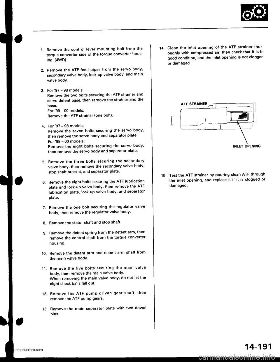
14, Clean the inlet opening of the ATF strainer thor-
oughly with compressed air, then check that it is in
good condition, and the inlet opening is not clogged
or damaged.
15.
INLET OPENING
Test the ATF strainer by pouring clean ATF through
the inlet opening, and replace it if it is clogged or
damaged.
14-191
www.emanualpro.com
Page 861 of 1395
lnspection and Adjustment
Pump Pressure Gheck With T/N 07406 - 0010001
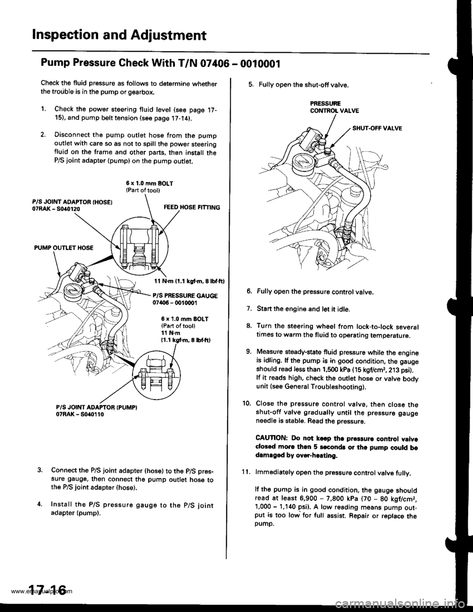
Check the fluid pressure as follows to determine whetherthe trouble is in the pump orgearbox.
1. Check the powsr steering fluid level (see page 17-15), and pump belt tension (see page 17-14).
2. Disconnect the pump outlet hose from the pump
outlet with care so as not to spill the pow€r steeringiluid on the frame and other pans. thon install theP/S joint adapter (pumpl on the pump outlet.
6 x 1.0 mm BOLT{Part oftool)
FEED HOSE FITTING
PUMP OUTLET HOSE
11 N.m ll.1 kgl.m, E lbf.ftl
P/S PRESSURE GAUGE07('6 - 0010001
6 x t.0 mm BOLT{Part oftool)11 N.m(1.1 kgt m, 8 lbf.tr)
Connect the P/S joint adapter (hose) to the p/S pres-
sure gauge, then connect the pump outlet hose tothe P/S ioint adspter (hose).
Install the P/S pressure gauge to the p/S joint
adapter (pump),
17-16
5. Fully open the shut-off valve.
PRESSURECONTROL VALVE
6. Fully open the pressure controlvatve.
7. Start the engine and let it idle.
8. Turn the steering wheel from lock-to-lock severaltimes to warm the fluid to operating temperature.
9, Measure steady-state fluid pressure while the engineis idling. lf the pump is in good condition, the gauge
should read less than 1,500 kPa (15 kgf/cmr, 213 psi).
lf it reads high, check the outlet hose or valve bodvunit (see General Troubleshooting).
10. Close the pressure control valve, then close theshut-off valve gradually until the pressure gauge
nsedle is stable. Read the pressure.
CAUTION: Do not k€ap tha prca3un control valvoclorod mo.c thon 5 srconds or thc pump cluld bodamEgod by ovor-hoating.
11. lmmodiately open the pressure controlvalve fullv.
lf the pump is in good condition, the gauge shouldread at least 6,900 - 7,800 kpa (70 - 80 kgflcmr,'1,000 - 1.140 psi). A low reading means pump out-put is too low for full assist. Repair or replace theDUMD.
www.emanualpro.com
Page 862 of 1395
Pump Pressure Check With T/N 07406 -
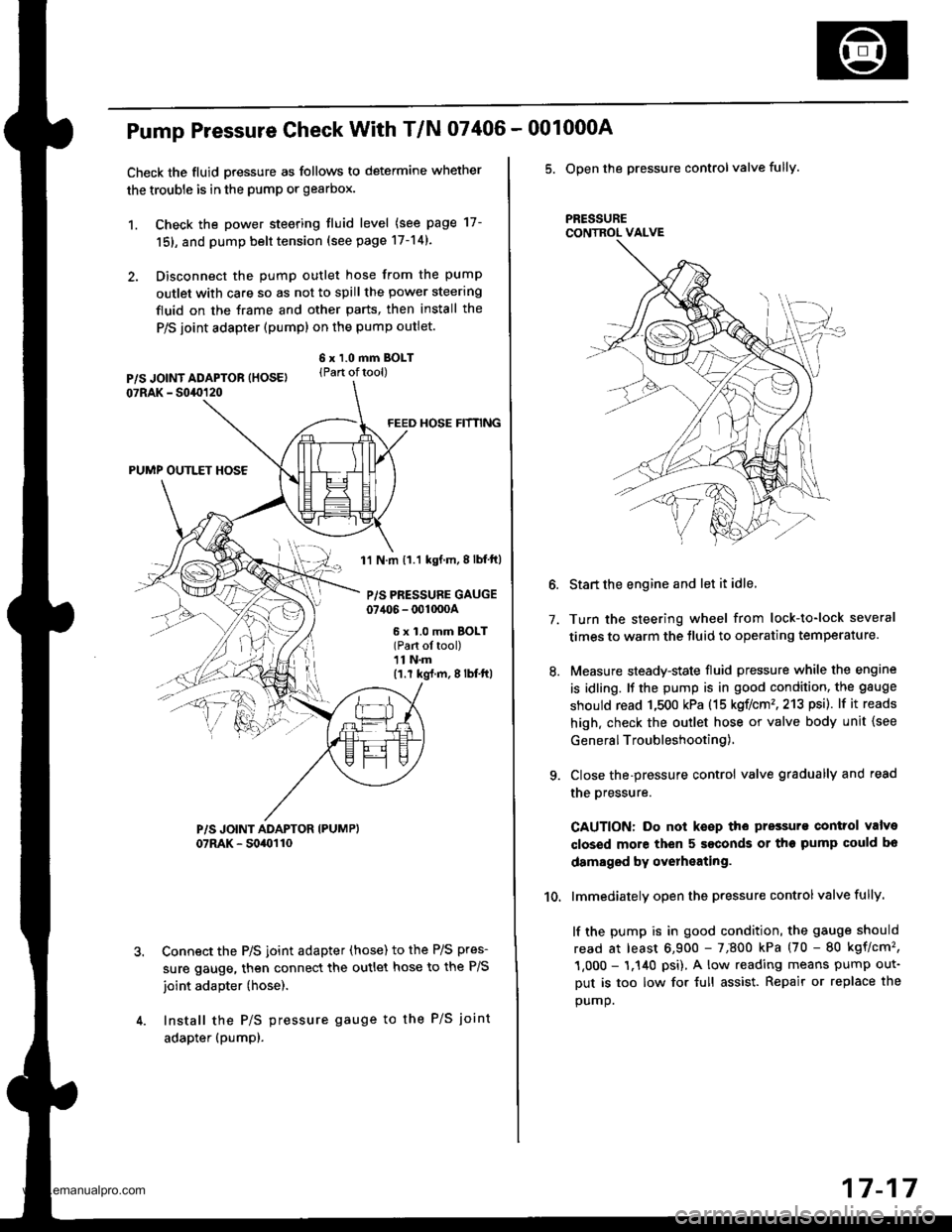
Check the fluid pressure as follows to determine whether
the trouble is in the pump or gearbox.
1. Check the power steering tluid level (see page 17-
151, and pump belt tension (see page 17-14).
2. Disconnect the pump outlet hose from the pump
outlet with care so as not to spill the power steering
fluid on the frame and other parts, then install the
P/S joint adapter (pump) on the pump outlet.
6 x 1.0 mm BOLT(Part oftool)
FEED HOSE HfNNG
PUMP OUTLET HOSE
1'l N.m 11.1 kgf.m,8lbf ft)
P/S PRESSURE GAUGE07406 - 001000A
6 x 1.0 mm BOLT(Part ol tool)11 N.m(1.r kg{.m,8lbf'ft|
Connect the P/S joint adapter (hose) to the P/S pres-
sure gauge, then connect the outlet hose to the P/S
joint adapter (hose).
Install the P/S pressure gauge to the P/S joint
adapter (pumpl.
001000A
5. Open the pressure controlvalve fully.
PRESSURECONTROL VALVE
7.
10.
Start the engine and let it idle.
Turn the steering wheel from lock-to-lock several
times to warm the tluid to operating temperature.
Measure steady-state fluid pressure while the engine
is idling. It the pump is in good condition, the gauge
should read 1,500 kPa (15 koflcm'�,213 psi). lf it reads
high. check the outlet hose or valve body unit {see
General Troubleshooting),
Close the-pressure control valve gradually and read
the oressure.
CAUTION: Do not keep the pressurs control valve
closed more then 5 seconds or the pump could bo
damaged by overheating.
lmmediately open the pressure controlvalve fully.
lf the pump is in good condition, the gauge should
read at least 6,900 - 7;800 kPa (70 - 80 kgflcm'�,
1,000 - 1.140 psi), A low reading means pump out-
Dut is too low for {ull assist. Repair or replace the
oumo.
17-17
www.emanualpro.com
Page 952 of 1395
ABS Control
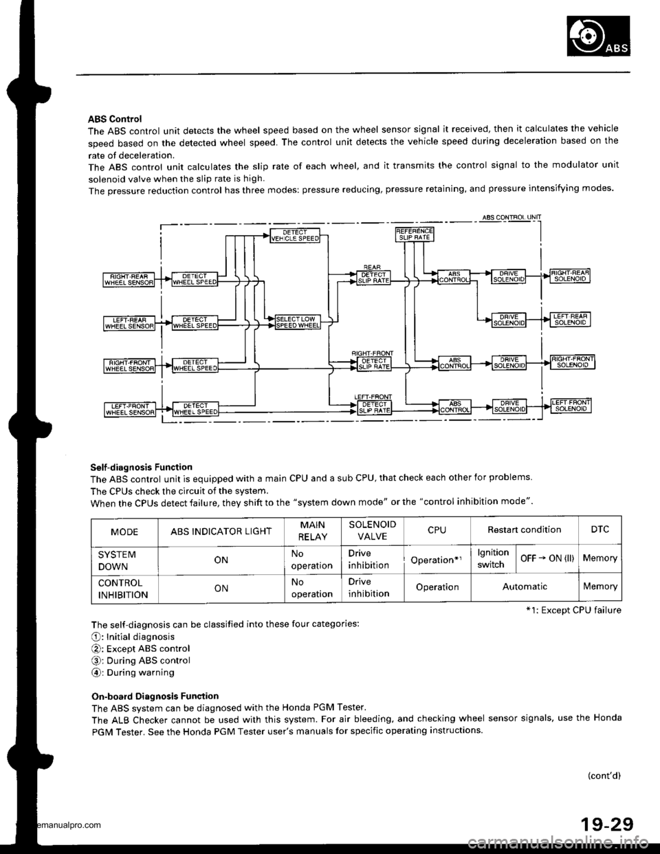
The ABS control unit detects the wheel speed based on the wheel sensor signal it received, then it calculates the vehicle
speed based on the detected wheel speed. The control unit detects the vehicle speed during deceleration based on the
rate of deceleration.
The ABS control unit calculates the slip rate of each wheel, and it transmits the control signal to the modulator unit
solenoid valve when the slip rate is high
The pressure reduction control has three modes: pressure reducing, pressure retaining, and pressure intensi{ying modes.
Self-diagnosis Function
The ABS control unit is equipped with a main cPU and a sub cPU, that check each other for problems.
The CPUs check the circuit of the system.
When the CPUS detect failure, they shift to the "system down mode" or the "control inhibition mode".
The self-diagnosis can be classitied into these four categories:
O: Initial diagnosis
O: Except ABS control
O; During ABS control
@: During warning
On-board Diagnosis Function
The ABS system can be diagnosed with the Honda PGM Tester.
The ALB Checker cannot be used with this system. For air bleeding. and checking wheel sensor signals, use the Honda
PGIM Tester. See the Honda PGM Tester user's manuals for specific operating instructions.
(cont'd)
19-29
ABS CONTROL I-INIT
MODEABSINDICATOR LIGHTMAIN
RE LAY
SOLENOID
VALVERestan conditionDTC
SYSTEM
DOWNONNo
operatron
Drive
inhibitionOperation*rlgnition
switchOFF - oN (ll)Memory
CONTROL
INHIBITIONONNo
operaton
Drive
inhibitionOperationAutomaticlVemory
*1: Except CPU failure
www.emanualpro.com
Page 960 of 1395
Kickback'1. The motor operates when the ABS is functioning. and the fluid in the reservoir is forced out to the master cylinder,
causing kickback at the brake pedal.
2. The ABS control unit operates the solenoid valve when the brake pedal is released after the initial diagnosis You may
hear the solenoid valve operate at this time, but it is normal
Pumo Motol
1. The pump motor operates when the ABS is functioning
2. The ABS control unit checks the pump motor operation during acceleration. You may hear the motor operate at this
time, but it is normal.
Brake Fluid Replacement/Ail Bleeding
L Brake fluid replacement and air bleeding procedures are the same as for vehicles without ABS To ease bleeding, start
with the front wheels.
Troubleshooting
1. The troubleshooting flowchart procedures assume that the cause of the problem is still present and the ABS indicator
is still on. Following the flowchart when the ABS indicator does not come on can result in incorrect diagnosis.
2. Ouestion the customer about the conditions when the problem occurred, and try to reproduce the same conditions
for troubleshooting.
Self-diagnosis is made at various times such as the initial diagnosis, except ABS control, during ABS control, during
acceleration, during the specified vehicle speed, etc. Therefore, the symptom canngt be checked unless the check
conditions match with the problem conditjons
3. When the ABS jndicator does not come on during the test-drive. but troubleshooting is performed based on the DTC,
check lor loose connectors, poor contact of the terminals, etc., before you start troubleshooting.
4. After troubleshooting, erase the DTC and test-drive the vehicle. Be sure the ABS indicator does not come on.
5. The connector illustratjons show the female terminals with a single outline and the male terminals with a double out-
l ne.
ABS Function Test
To simulate ABS operation and activate the solenoid valves and pump, use the Honda PGM Tester.
Connect the PGM Tester to the 16P Data Link Connector (DLC). When the System Select menu is displayed, select the ABS
Test Mode menu, and follow the tester's prompts.
19-37
www.emanualpro.com