gearbox HONDA CR-V 1999 RD1-RD3 / 1.G Owner's Guide
[x] Cancel search | Manufacturer: HONDA, Model Year: 1999, Model line: CR-V, Model: HONDA CR-V 1999 RD1-RD3 / 1.GPages: 1395, PDF Size: 35.62 MB
Page 895 of 1395

Power Steering Gearbox
Reassembly (cont'd)
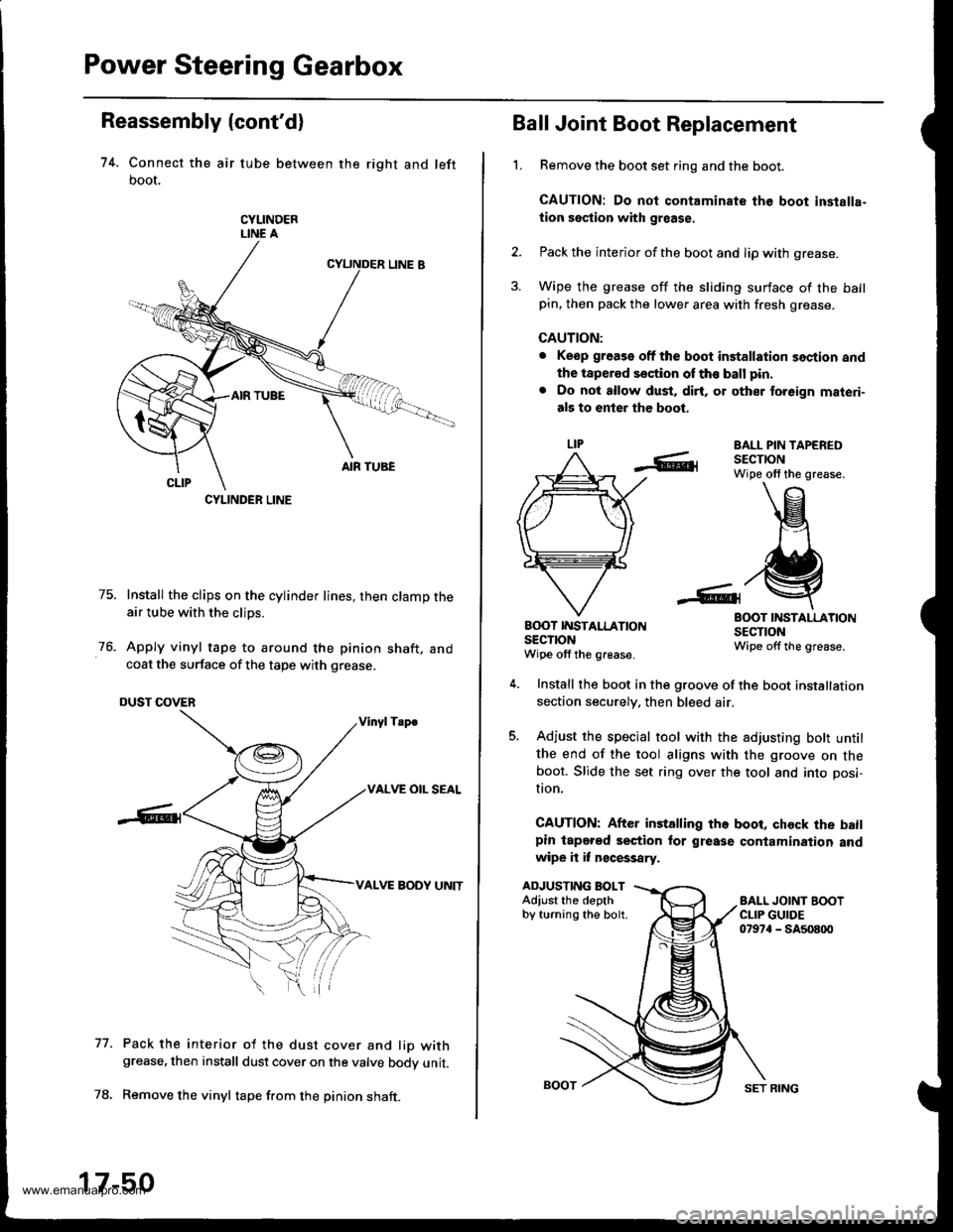
74. Connect the air tube between the right and left
boot,
CYLINDERLINE A
75. Install the clips on the cylinder lines, then clamp theair tube with the clips.
76. Apply vinyl tape to around the pinion shaft, andcoat the surface of the tape with grease.
DUST COVER
Vinyl Tsp€
VALVE OIL SEAL
VALVE BODY UNIT
Pack the interior of the dust cover and lio withgrease, then install dust cover on the valve bodv unit.
Remove the vinyl tape f.om the pinion shaft.
77.
CYLINDER LINE
17-50
SET RING
't.
Ball Joint Boot Replacement
Remove the boot set ring and the boot.
CAUTION: Do not contaminate the boot inslalla-
tion section with graase.
Pack the interior of the boot and lip with grease.
Wipe the grease off the sliding surface of the ballpin. then pack the lower area with fresh grease.
CAUTION:
. Keep grease off the boot installation section and
the tapered section of th€ ball pin.
. Do not allow dust, dirt, or other to.eign materi-
als to enter the boot.
EALL PIN TAPEREDSECTIONWipe olf the grease.
BOOT INSTALLATIONSECTIONWipe offthe grease.
B(X)T IT{STALLATIONsEclroNWipe off the grease.
ADJUSTING BOLTAdiust the depthby turning the bolt.
Install the boot in the groove of the boot installation
section securely. then bleed air.
Adjust the special tool with the adjusting bott untilthe end of the tool aligns with the groove on theboot. Slide the set ring over the tool and into posi-
I|on.
CAUTION: After installing the boot, chock the batlpin lapered section for grease contamination andwipe it it n€cessary.
www.emanualpro.com
Page 896 of 1395

lnstallation
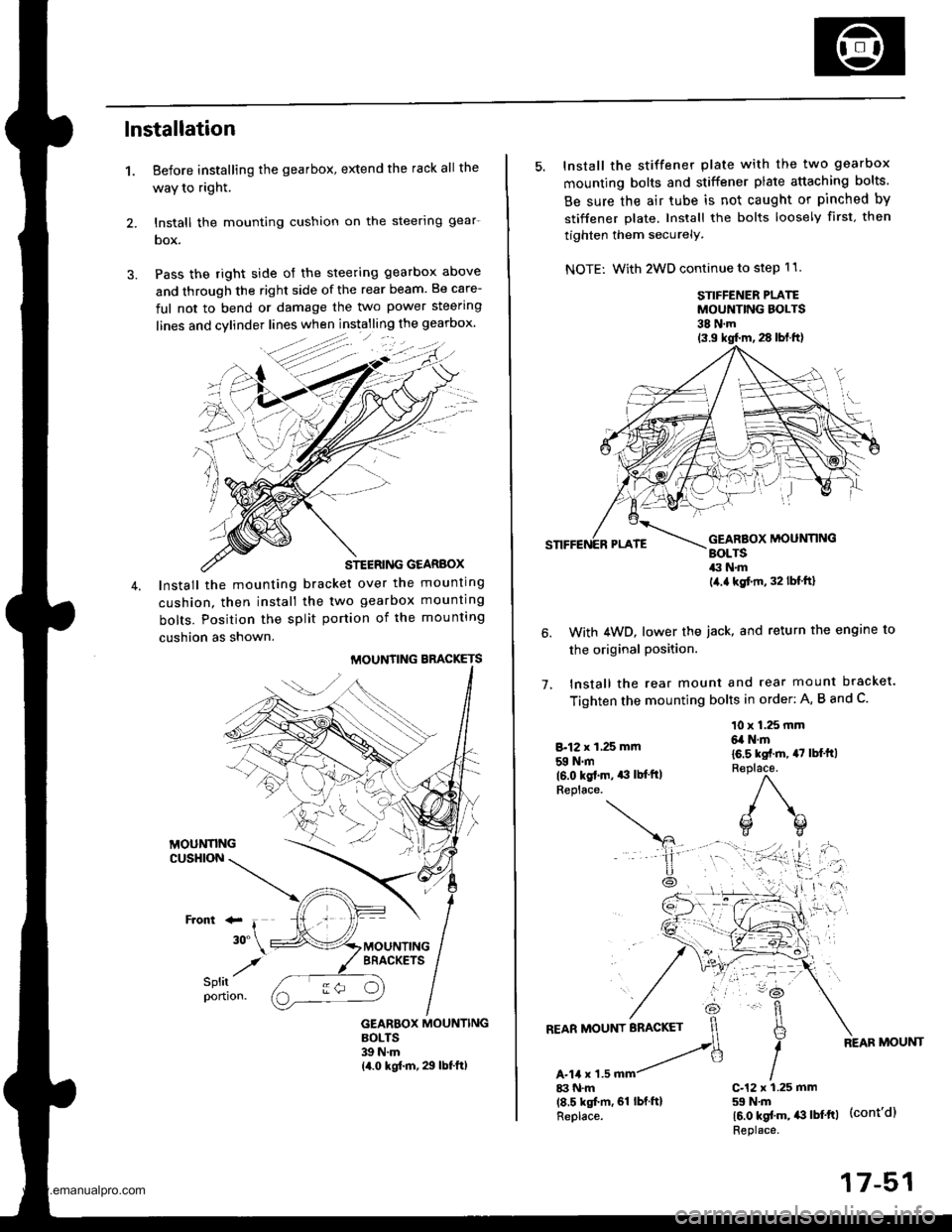
1. Before installing the gearbox, extend the rack all the
waY to right.
2. lnstall the mounting cushion on the steerlng gear-
box.
3. Pass the right side of the steering gearbox above
and through the right side of the rear beam. Be care-
ful not to bend or damage the two power steering
STEERING GEARBOX
Install the mounting bracket over the mounting
cushion. then install the two gearbox mounting
bolts. Position the split portion of the mounting
cushion as shown.
MOUNTING BBACKETS
GEARBOX MOUNTINGBOLTS39 N.m14.0 kgf.m, 29 lbf.ft)
:-
/
5. Install the stiffener plate with the two gearbox
mounting bolts and stiffener plate attaching bolts.
Be sure the air tube is not caught or pinched by
stiffener plate. Install the bolts loosely first. then
tighten them securely.
NOTE: With 2WD continue to step 11.
STIFFENER PLATEMOUNTING BOLTS38 N.m
1.
With 4WD, lower the iack, and return the engine to
the original Position.
lnstall the rear mount and rear mount bracket.
Tighten the mounting bolts in order: A, B and C.
8.12 x 1,25 mm
59 N.m(6.0 kgt.m. *l lb{'ftlReplace.
10 x 1.25 mm6,a N.m
16.5 kst.m, 47 lbl'ft)R€place.
)\^
o(]
17-51
www.emanualpro.com
Page 897 of 1395

Power Steering Gearbox
Installation (cont'd)
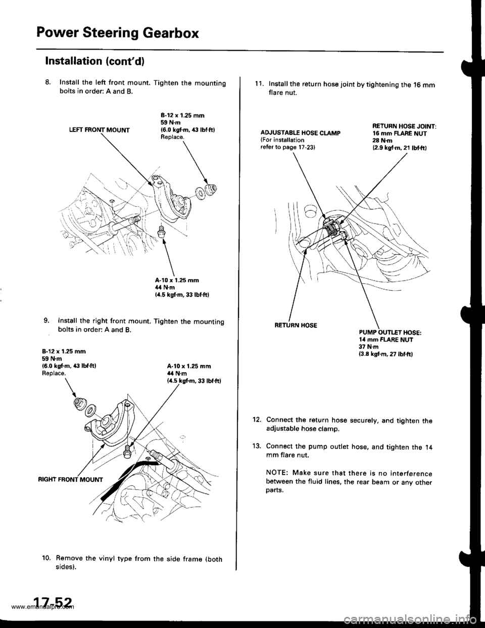
8, Install the left front mount. Tighten the mountingbolts in order: A and B.
LEFT FRONT MOUNT
B-12 x 1,25 mm59Nm(6.0 kgtm,,€ lbl.ftlReplaca.
9. Instsll the right front mount, Tighten the mountingbolts in order: A and B.
B-12 x 1.25 mm59 N.m16.0 ks[.m, ,|:| lbf.ftlReplace.
A-10 x 1.25 mm4,1 N.mla.s kgt m, 33 lbf.ft)
A-10 x 1.25 mma,a N.m
10. Remove the vinyl type from the side frame (both
sides).
17-52
11. Installthe return hose joint by tightening the 16 mmflare nut.
AD.'USTAB[T HOSE CLAMP(For installationreter to page 17,23)
RETURN HOSE JOINT:16 mm FLARE NUT28 N.m12.9 kg{.m.21 lbt{t)
14 mm FLARE NUT37 N.m(3.8 ksf.m, 27 lbl'frl
't2.
13.
Connect the return hose securely. and tighten theadjustable hose clamp.
Connect the pump outlet hose, and tighten the l4mm flare nut.
NOTE: Make sure that there is no interferencebetween the fluid lines, the rear beam or any otherparts.
www.emanualpro.com
Page 898 of 1395

't 4.
15.
Center the steering rack within its stroke.
Install the steering joint, and reconnect the steering
shaft and pinion shaft.
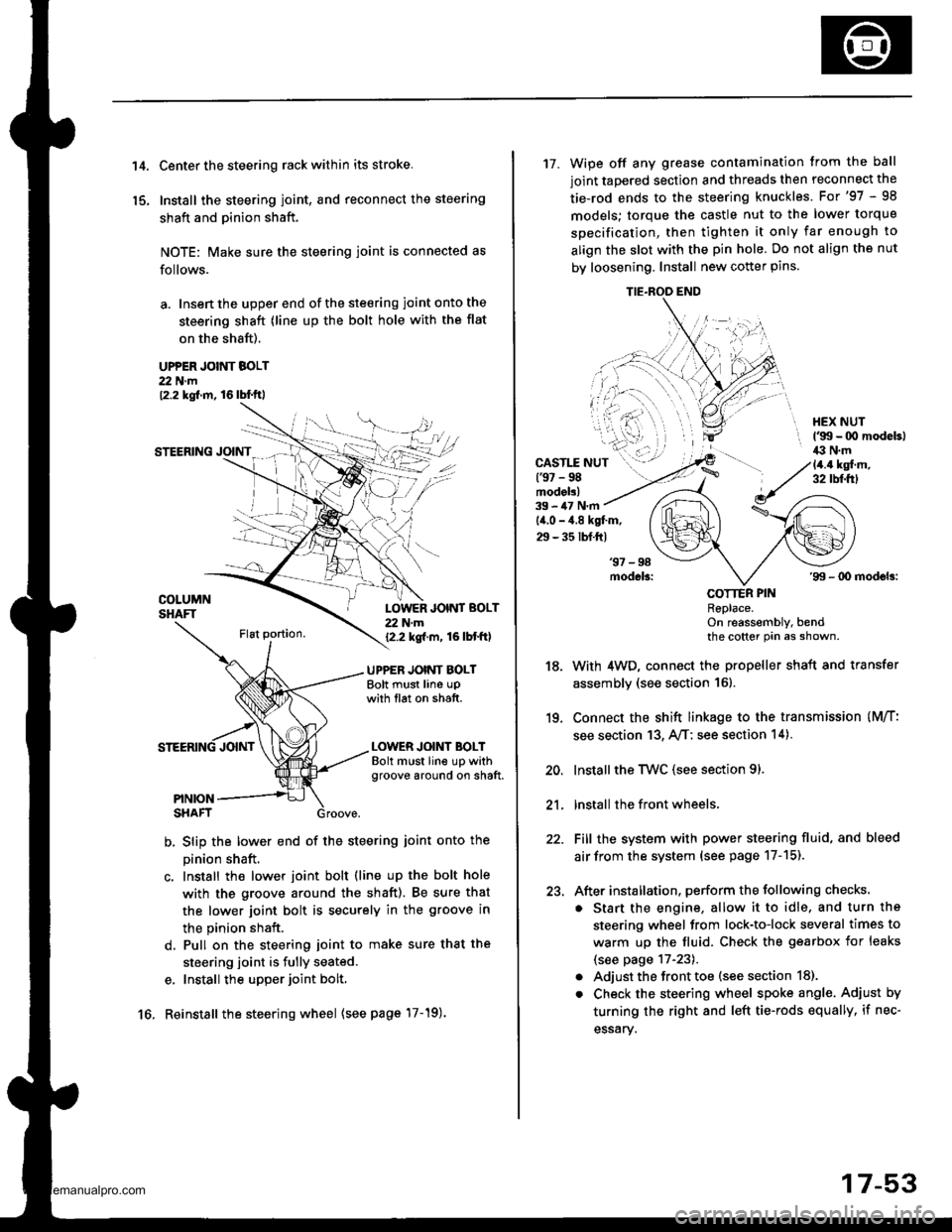
NOTE: Make sure the steering joint is connected as
follows.
a. Insen the upper end of the steering joint onto the
steering shaft (line up the bolt hole with the flat
on the shaft).
UPPER JOINT BOLT22 N.m12.2 kgf.m, 16lbl.ft,
STEERING JOINT
COLUMNSHAFTLOWER JOINT BOLT22 N.m12.2 kgf.m, 16lbtftl
UPPER JOINT BOLTBolt must line upwith tlat on shatt.
LOWER JOINT BOLTBolt must line up withgroove around on shaft.
PINIONSHAFT
b, Slip the lower end of the steering ioint onto the
pinion shaft.
c. Install the lower joint bolt (line up the bolt hole
with ths groove around the shaft). Be sure that
the lower joint bolt is securely in the groove in
the pinion shaft.
d. Pull on the steering joint to make sure that the
steering joint is fully seated.
e, Install the upper joint bolt,
Reinstall the steering wheel {see page'17-19).16.
17-53
17. Wipe off any grease contamination trom the ball
joint tapered section and threads then reconnect the
tie-rod ends to the steering knuckles. For'97 - 98
models; torque the castle nut to the lower torque
specification, then tighten it only far enough to
align the slot with the pin hole. Do not align the nut
by loosening. Install new cotter pins.
CAST1T NUT(9t - 98modol!)
HEX NUTl'g!t - 00 modeb)il:l N.m14.4 ksl.m,32 tbf.f0
39 - iU N'm
lil.o - 4.8 kgl.m,
29 - 35 tbf.ftl
18.
19.
20.
21.
22.
23.
'99 - lD modeb:
COTTER PINRePlace.on reassembly, bendthe cotter Pin as shown.
With 4WD, connect the propeller shaft and transfer
assembly (see section 16).
Connect the shift linkage to the transmission (M/T:
see section 13, A,/T; see section 14).
Installthe Twc (see section 91.
lnstall the front wheels,
Fill the system with power steering fluid, and bleed
air from the system (see page 17-15).
After installation. perform the following checks.
. Start the engine, allow it to idle, and turn the
steering wheel from lock-to-lock several times to
warm up the fluid. Check the gearbox for leaks
(see page 17-23).
. Adjust the front toe (s€e section 18).
. Check the steering wheel spoke angl€. Adjust by
turning the right and left tie-rods equally, if nec-
essary.
TIE.ROO END
www.emanualpro.com