hub HONDA CR-V 1999 RD1-RD3 / 1.G Owner's Guide
[x] Cancel search | Manufacturer: HONDA, Model Year: 1999, Model line: CR-V, Model: HONDA CR-V 1999 RD1-RD3 / 1.GPages: 1395, PDF Size: 35.62 MB
Page 812 of 1395
Rear Differential Assembly
Disassembly (cont'dl
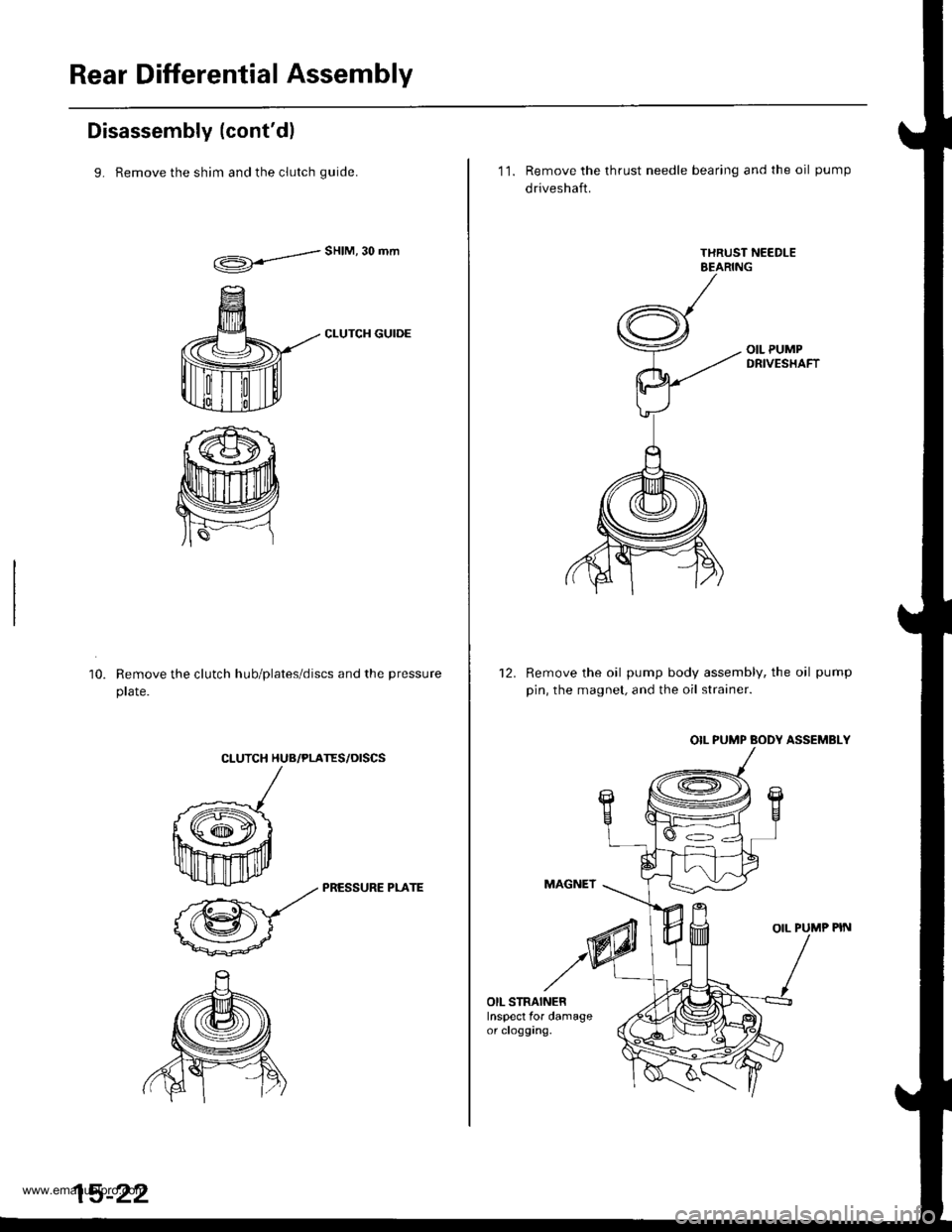
9. Remove the shim and the clutch quide.
d"HIM'30mm
CLUTCH GUIDE
Remove the clutch hub/plates/discs and the pressure
prare.
10.
CLUTCH HUB/PLATES/OISCS
k
ffi-:*
_zz PRESSURE PLArE
@-
15-22
11. Remove the thrust needle bearing and the oil pump
driveshaft.
Remove the oil pump body assembly, the oil pump
pin, the magnet, and the oil strainer.
OIL PUMP BODY ASSEMBLY
MAGNET
OIL PUMP PIN
12.
OIL STRAINERInspect for damageor clogging.
www.emanualpro.com
Page 814 of 1395
Rear Differential Assembly
Reassembly (cont'dl
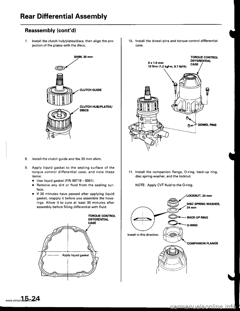
7. Install the clutch hub/plates/discs, then align the pro-
jection of the plates with the discs.
M, 30 mm
CLUTCH GUIDE
sHl
,/
.A-\,/r\-7
8.
9.
CLUTCH HUA/PLATES/Dtscs
Installthe clutch guide and the 30 mm shim.
Apply liquid gasket to the sealing surface of the
torque control differential case, and note these
rlems:
. Use liquid gasket (P/N 08718 - 0001).
. Remove any dirt or fluid from the sealing sur-
face.
. lf 20 minutes have passed after applying liquid
gasket, reapply it before you assemble the hous-
ings. Allow it to cure at least 30 minutes after
assembly before filling differential with fluid.
TOBOUE CONTROLDIFFERENNAL
--- Apply liquid gaskot
15-24
6x1.0mm12 N.m 11.2 tgf m,8.7lbt.ftl
10. lnstall the dowel pins and toroue control differential
case.
TOROUE CONTNOL
11. Install the companion flange, O-ring, back-up ring,
disc spring washer, and the locknut.
NOTE: Apply CW fluid to the O-ring.
,24mm
DISC SPRING WASHER,2a mm
lnstall in this direction.
@+-_alcr-upnwc
COMPANION FLAI{GE
/r-
K@#/
www.emanualpro.com
Page 820 of 1395
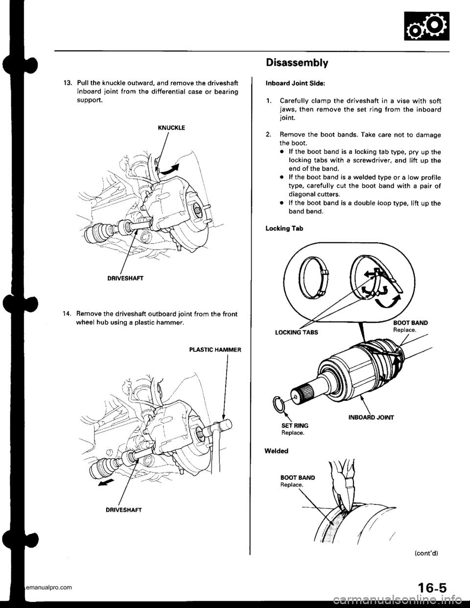
13, Pull the knuckle outward, and remove the driveshaft
inboard joint from the differential case or bearing
suoDort.
KNUCKLE
Remove the driveshaft outboard joint from the front
wheel hub using a plastic hammer.
PLASTIC HAMMER
14.
DRIVESHAFT
DRIVESHAFT
Disassembly
Inboard Joint Sid€:
1, Carefully clamp the driveshaft in a vise with softjaws, then remove the set ring from the inboardjoint.
2. Remove the boot bands. Take care not to damage
the boot,
. lf the boot band is a locking tab type, pry up the
locking tabs with a screwdriver, and lift up the
end of the band.
. lf the boot band isawelded typeora low profile
type, carefully cut the boot band with a pair of
diagonal cutters.
. lf the boot band is a double loop type. lift up the
band bend.
Locking Tab
SET BINGReplace.
Welded
{cont'd)
16-5
www.emanualpro.com
Page 837 of 1395
Rear Driveshafts
't.
Removal
Loosen the rear wh€el nuts slightly.
Raise the rear of the vehicle, and support it withsafety stands in the proper locations (see section 1),
Remove the wheel nuts and rear wheets.
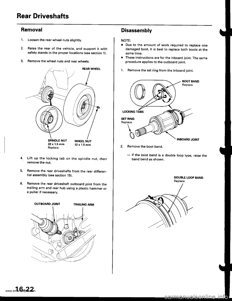
SPINDLE NUT22 x 1.5 mmReplace.
WHEEL NUT12 x 1.5 mm
4.Lift up the locking tab on the spindle nut. thenremove the nut.
Remove the rear driveshafts from the rear differen-tial assembly (see section 15),
Remove the rear driveshaft outboard joint from thetrailing arm and rear hub using a plastic hammer ora puller if necessary.
TRAILING ARMOUTBOARD JOINT
16-22
Disassembly
NOTE:
a Due to the amount of work required to replace onedamaged boot, it is best to replace both boots at thesame time.
. These instructions are for the inboard joint. The sameprocedure applies to the outboard joint.
1, Remove the set ring from the inboard joint,
BOOT BANDReplace.
INBOARD JOINT
2. Remove the boot band.
- lf the boot band is a double loop type, raise theband bend as shown,
DOUSLE LOOP BANDReplace.
www.emanualpro.com
Page 846 of 1395

Steering
Special Toofs ............. 17-2
Component Locations
Index ................ ....... 17-3
Troubleshooting
General Troubleshooting ................ 1 7-4
Noise and Vibration ......................... 17-8
Fluid Leaks ............. 17-10
Inspection and Adiustment
Steering Operation .......................... 17-12
Power Assist Check
With Vehicle Parked ....................
Steering Linkage and Gearbox .......
Pump Belt
Rack Guide Adjustment ...................
Fluid Rep|acement ...................,,.,....
Pump Pressure Check .................,,...
*Steering Wheel
Removal ................. 17-18
*Steering Column
Removal/lnstallation ................ ....... 17 -2O
lnspection .............. 17-21
Steering Lock Replacement ............ 17 -22
Power Steering Hoses, Lines
Ffuid Leakage Inspection ................. 17 -23
Repfacement .......... 17-23
Power Steering Pump
Repfacement .......... 17-24
Disassembly ...........17-25
fnspection .............. 17-26
Reassembly ............ 17-28
Power Steering Gearbox
Removal ................. 17-31
Disassembly ........... 17-34
Reassembly ............ 17-40
Ball Joint Boot Replacement .......... 17-50
Installation ............. 17-51
17-12
17-13
17-14
l7-15
17-15
17-16
Disassembly/Reassembly............... 17-18
4'%/b.......... -r'-7--a/
SUPPLEN\EN AL RES\RA(N SYSTES{ (SRS\
This model has an SRS which includes a driver's airbag in the steering wheel hub. a passenger's airbag in the dashboardabove the glove box ('97 - 00 models), and seat belt tensioners in the seat belt retractors ('98 - 00 models). Informationnecessary to safely service the SRS is included in this Service Manual. ltems marked with an asterisk (*) on the contentspage include, or are located near, SBS components. Servicing. disassembling or replacing these items will require specialprecautions and tools, and should only be done by an authorized Honda oearer.
To avoid rendering the SRS inoperative, which could lead to peFonal iniury or death in the event of a sevore trontalcollision. allSRS service work must be performod by an authorized Honda dealer.lmproper service procedurgs, including incorrect removal and installalion of the SRS, could lead to personal iniurycaused by unintontional deployment of th€ airbags {'97 - 00 models), and seat belt tensioners ('98 - 00 modelsl.Do not bump the SRS unit. Otherwise, the system may lail in case ot a collision, or the airbags may deploy when theignition switch is ON (lll.
SRS electrical wiring harnesses are identitied by yellow colof coding. Ralated components are located in the steeringcolumn, front console, dashboard, dashboard lower panel, and in the dashboard above the glove box. Do not use elec-trical test equipment on these cilcuits,
www.emanualpro.com
Page 863 of 1395
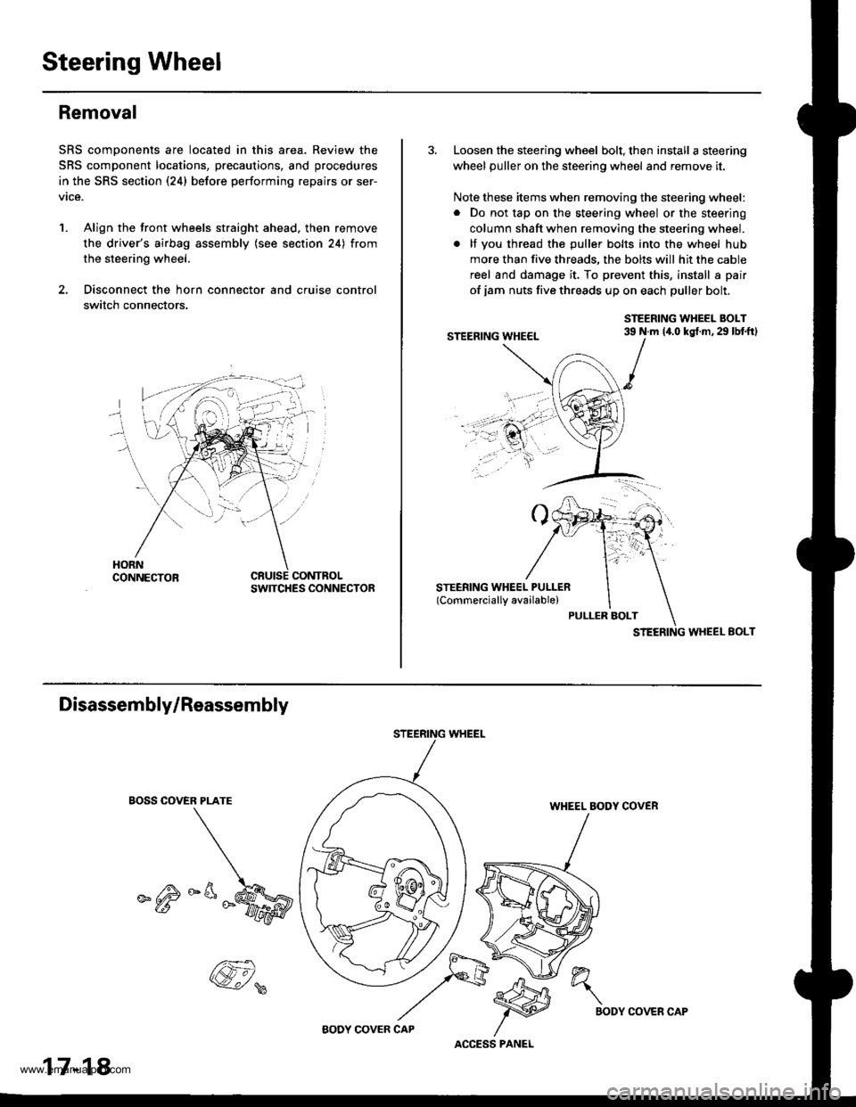
Steering Wheel
Removal
SRS components are located in this area. Review the
SRS component locations, precautions, and procedures
in the SRS section (24) before performing repairs or ser-
vice.
1. Align the front wheels straight ahead. then remove
the driver's airbag assembly (see section 24) from
the steering wheel.
2. Disconnect the horn connector and cruise control
switch connectors.
CONTROLSWITCHES CONNECTOR
3. Loosen the steering wheel bolt, then install a steering
wheel puller on the steering wheel and remove it.
Note these items when removing the steering wheel:
. Do not tap on the steering wheel or the steering
column shaft when removing the steering wheel.
. lf you thread the puller bolts into the wheel hub
more than five threads, the bolts will hit the cable
reel and damage it. To prevent this, install a pair
of jam nuts five threads up on each puller bolt.
STEERING WHEEL BOLT39 N.m 14.0 kgt.m,29 lbtftl
STEERING WHEEL EOLT
Disassembly/Reassembly
EOSS COVER PLATE
_^M
STEERING WHEEL
WHEEL BODY COVER
17-18
@,
ACCESS PANEL
h"\
BODYCOVER CAP
www.emanualpro.com
Page 899 of 1395
Suspension
Special Tools ............. 18-2
Component Locations
lndex ................ ...... 18-3
Wheel Alignment
Service lnformation ......................,.. 18-4
Camber .................. 18-4
Caster ............... ...... 18-5
Front Toe Inspection/
Adiustment ........ 18-5
Rear Toe Inspection/
Adiustment ........ 18-6
Turning Angle Inspection/
Adiustment ........ 18-6
Wheel/Hub Inspection
Bearing End Play .......................,...... 18-7
Wheel Runout ....... 18-7
Front Suspension
Suspension Arms Replacement ..... 18-8
Knuckle/Hub Replacement ............. 18-9
Lower Ball Joint Replacement ....... 18-15
Ball Joint Boot Replacement .......... 18-16
Front Damper
Removal ................. 18-16
Disassembly/lnspection .................. 18-1 7
Reassembly ........... 18-18
lnstallation ............. 18-18
Rear Suspension
Suspension Arms Replacement ..... 18-19
Hub Bearing Unit Replacement ...... 18-20
Upper Arm Bushing
Replacement ..... 18-23
Rear Damper
Removal ................. 18-23
Disassembly/1nspection .................. 18-24
Reassembly ........... 18-25
lnstallation ............. 18-25
www.emanualpro.com
Page 900 of 1395
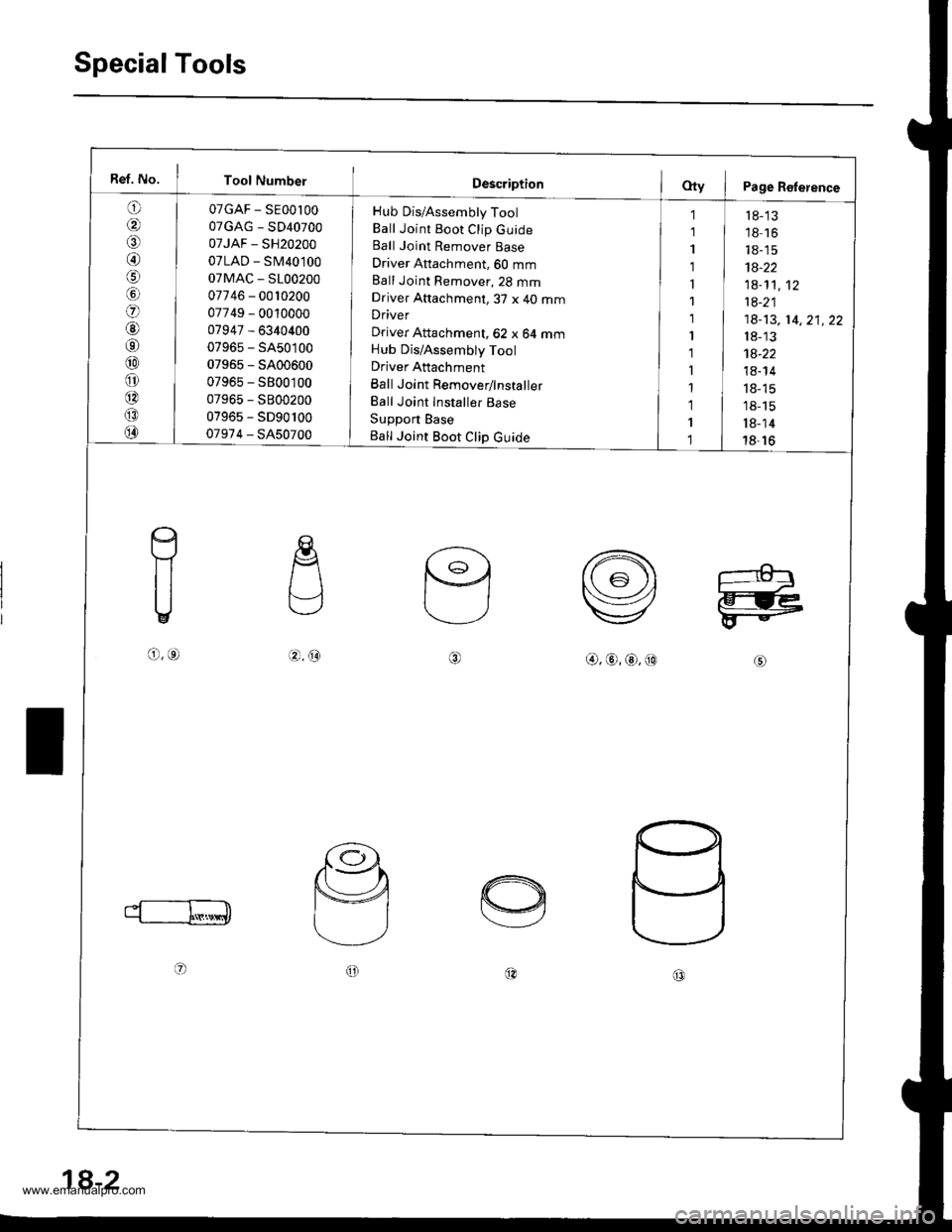
SpecialTools
Ref. No. I Tool Number
o
/a
@/6
lol
o
@6r
@
o
@
@
@
07GAF - SE00l00
07GAG - SD40700
07JAF - SH20200
07LAD - SM40100
07MAC - S100200
07746 - 0010200
07749 - 0010000
07947 - 6340400
07965 - SA50100
07965 - 5400600
07965 - S800100
07965 - S800200
07965 - SD90100
07974 - SA50700
Hub Dis/Assembly Tool
Ball Joint Boot Clip GuideBall Joint Remover Base
Driver Attachment, 60 mm
Ball Joint Remover,23 mmDriver Attachment,3T x 40 mmDriver
Driver Attachment, 62 x 64 mmHub Dis/Assembly Tool
Driver Attachment
Ball Joint Remover/lnstaller
Ball Joint Installer Base
Support Base
Ball Joint Boot Clip Guide
1
1
1
1
1
1
1
1'l
I
1
1
I
1
r 8-'13'18 16
18-15
1A-22
1a-1't,12
1a-21
18-13, 14,21,22
18-13
1a-22
18- 14
18- 15
18-15
l8-14
18-16
c
f1
U
o,o.4.@@,@,@,@
oo@c0
18-2
www.emanualpro.com
Page 905 of 1395
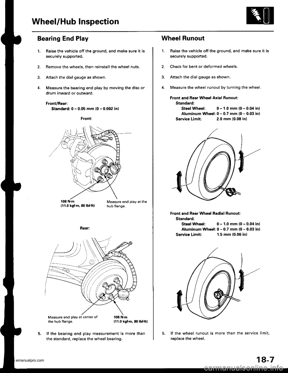
Wheel/Hub lnspection
Bearing End Play
1.Raise the vehicle off the ground, and make sure it is
securely supported.
Remove the wheels, then reinstall the wheel nuts.
Attach the dial gauge as shown.
Measure the bearing end play by moving the disc or
drum inward or outward.
Front/Rear;
Standard: 0 - 0.05 mm (0 - 0.002 in)
Measure end play at thehub flange.
Rear:
Measure end play at center ofthe hub flange.108 N.m{11.0 kgf.m, q} lbf.ftl
It the bearing end play measurement is more than
the standard, replace the wheel bearing.
1.
Wheel Runout
Raise the vehicle off the ground, and make sure it is
securely supported,
Check for bent or deformed wheels.
Attach the dial gauge as shown.
Measure the wheel runout by turning the wheel.
Front and Rear Whoel Axial Runout:
Standard:
Steel Wheel: 0 - 1.0 mm {0 - 0.0i[ in]
Aluminum Wheel: 0 - 0.7 mm l0 - 0.03 in)
Service Limit:2.0 mm 10.08 inl
Front and Rear Wheel Radial Runout:
Standard:
Steel Whoal: 0 - 1.0 mm (0 - 0.04 inl
Aluminum Whoel: 0 - 0.7 mm {0 - 0.03 in}
Servics Limit:1.5 mm (0.06 inl
lf the wheel runout is more than the service limit,
reolace the wheel.
18-7
www.emanualpro.com
Page 907 of 1395
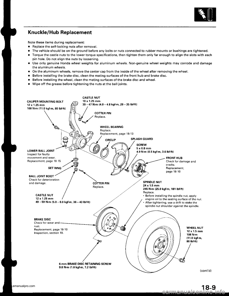
Knuckle/Hub Replacement
Note these items during replacement:
. Replace the selt-locking nuts after removal.
. The vehicle should be on the ground before any bolts or nuts connected to rubber mounts or bushings are tightened.
. Torque the castle nuts to the lower torque specifications, then tighten them only far enough to align the slots with each
pin hole. Do not align the nuts by loosening.
o Use only genuine Honda wheel weights for aluminum wheels. Non'genuine wheel weights may corrode and damage
the aluminum wheels.
. Onthealuminum wheels, remove the center cap from the inside of the wheel after removing the wheel.
. Before installing the brake disc, clean the mating surfaces of the front hub and brake disc.
. Before installing the wheel. clean the mating surfaces ofthe brake disc and wheel.
. Wipe off the grease before tightening the nuts at the balljoints.
CALIPER MOUNTING BOLT12 x 1.25 mm108 N.m (11.0 kgtm.80 lbt.ftl
LOWER BALL JOINTInspect for faultymovement and wear,Replacement, page'18 15
CASTLE NUT10 x 1.25 mm39 - 47 N.m (i1.0 - 4.8 kgf.m, 29 - 35 lbf.ftl
COTTER PINReplace.
WHEEL BEARINGBeplace.Replacement, page 18-13
CIRCLIPSPLASH GUARD
SCREW5x0.8mm4.9 N.m {0.5 kgf.m,3.6lbf.ft)
SET RING
FRONT HUBCheck for damage and
Replacement,page 18 10
BALL JOINT BOOTCheck for deteriorationano oamage.SPINOLE NUT24 x 1.5 mm245 N.m {25.0 kgI.m, 181 lbtft}Replace.. Before installing the spindle nut, applyengine oil to the seating surface of the nut.. After tightening, use a drift to stake thespindle nut shoulder against the spindle.
COTTER PINReplace.
CASTLE NUT12x 1.25 fim49 - 59 N.m 15.0 - 6.0 kgt.m. 36 - € lbf.ft)
BRAKE DISCCheck for wear andrust.Replacement, page 18-10Inspection, section 19.
WHEEL NUT12 x 1.5 mm108 N.m{11.0 kgt m,80 tbf.ftl
6 mm BRAKE DISC RETAINING SCREW9.8 N.m (1.0 kgtm, 7.2 lbtftl(cont'd )
18-9
www.emanualpro.com