Light diag HONDA CR-V 1999 RD1-RD3 / 1.G Service Manual
[x] Cancel search | Manufacturer: HONDA, Model Year: 1999, Model line: CR-V, Model: HONDA CR-V 1999 RD1-RD3 / 1.GPages: 1395, PDF Size: 35.62 MB
Page 1161 of 1395

Body Electrical
Speciaf Toofs ,...,..,.............-.23-2
Troubleshooting
Tips and Precautions ......,.,..........,.................. 23-3
Five-step Troubleshooting ........,.,.,...,,.,......... 23-5
Wire Color Codes ...,....,.. 23-5
Relay and Control Unit Locations
Engine Compartment ..,.,......,......................... 23-6
Dashboard ,.,.,..............-.- 23-7
Door ....................... .........23-10
Index to Cilcuits and Sysiems
Accessory Socket .. ,....,.,..,.,. 23-95*Airbags ................ .,....,. Sestion 24
Air Conditioning ,.,.,.... Section 22
Alternator ................... Section 4
Anti-lock Brake System {ABSI ................... Section 19'A/T Gear Position Indicator ....................... Section 1,1
Automatic Transmission System ...........,.. Section 14
Battery ................... ..............23-50
Blower Controls .,...,.,, Section 22
Charging System ....... Seqtion il
Clock -'98 Model ................ 23-98
Connector ldentification and Wire HarnessRouting .................. ......... 23.11
Cruise Control ............ Ssction 4
Dash Lights Brightness Contlo||er ..................... 23-90
Fan Conlrols ...,......,.... Section 10
Fuel Pump ,..,.,...,....,.... Section 11
Fuses...................... .,,.,.,.,.,,.,23-40*Gauges
Circuit Diagram ......-....-..23-58
Fuel Gauge .....,.,..... Section 11
Speedometer ..,..........,... 23-56
Ground Distribution ,....,.,...23-46
Hatch Glsss ODenor .........................,.,.,.,.,..,.,.,.,,. 23-121
Heater Controls .-........ Soction 21*Horns.,...,..,.,.,....... ................23"104*fgnition Switch ,,.,.,..,.,.,,.,.,.,23-51
lgnition Key Light System -'97 Mod6l .............. 23.88
-+
BODY
www.emanualpro.com
Page 1165 of 1395
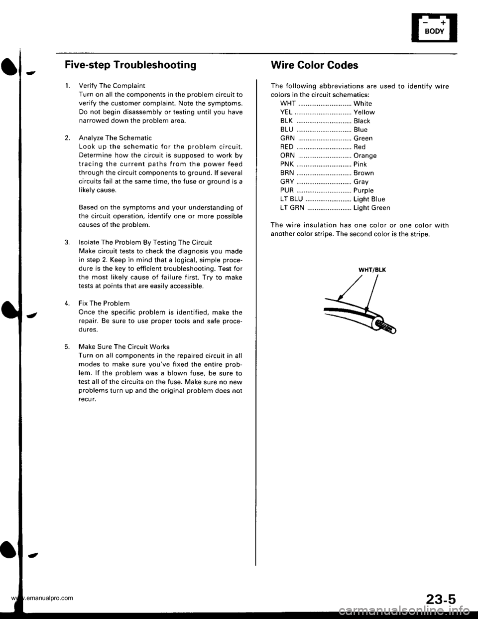
Five-step Troubleshooting
1.
3.
Verify The Complaint
Turn on all the components in the problem circuit to
verify the customer complaint. Note the symptoms.
Do not begin disassembly or testing until you have
narrowed down the problem area.
Analyze The Schematic
Look up the schematic for the problem circuit.
Determine how the circuit is supposed to work by
tracing the current paths from the power feed
through the circuit components to ground. lf several
circuits fail at the same time, the fuse or ground is a
likely cause,
Based on the symptoms and your understanding of
the circuit operation, identify one or more possible
causes of the problem.
lsolate The Problem By Testing The Circuit
Make circuit tests to check the diagnosis you made
in step 2. Keep jn mind that a logical, simple proce-
dure is the key to efficient troubleshooting. Test for
the most likely cause of failure first. Try to make
tests at points that are easily accessible,
Fix The Problem
Once the specific problem is identified, make the
repair. Be sure to use proper tools and safe proce-
dures.
Make Sure The Circuit Works
Turn on all components in the repaired circuit in all
modes to make sure you've fixed the entire prob-
lem. lf the problem was a blown fuse, be sure to
test all of the circuits on the fuse. lvlake sure no new
problems turn up and the original problem does nol
recur.
4.
O
Wire Color Codes
The following abbreviations are used to identify wire
colors in the circuit schematics:
WHT ............................. White
YEL,.............................. Yellow
BLK ..........,................... Black
BLU .............................. Blue
GRN .............................Green
RED .............................. Red
ORN .............................Oran9e
PNK.....,........................ Pink
BRN .............................. Brown
GRY .............................. Gray
PUR .........,.................... Purple
LT BLU ..................,...... Light Blue
LT GRN ........................ Light Green
The wire insulation has one color or one color with
another color stripe. The second color is the stripe.
WHT/BLK
www.emanualpro.com
Page 1218 of 1395
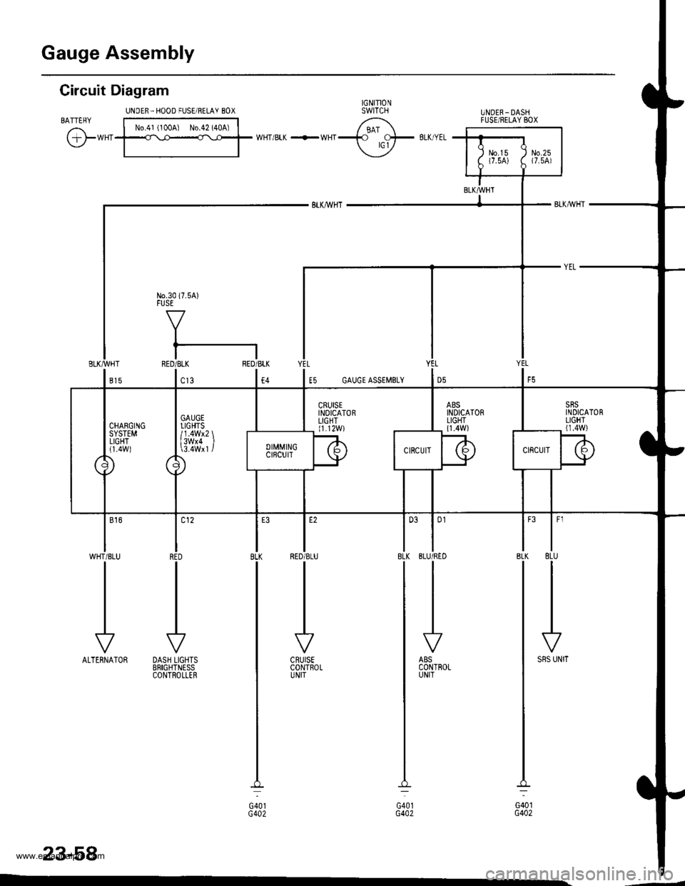
Gauge Assembly
Circuit Diagram
BATTERY
@*"
UNOER.IIOOD FUSE/RELAY 8OX
No.41 (100A) No.42 (40A)
UNOER_DASHFUSEiNELAY BOX
|
'''
IRED
-I
DASH LIGHTSBRIGHTNESSCONTROLLER
l-8LK
G401G4A2
CRUISECONTROLUNIT
23-58
JALTERNATOR
| 0l
IBLU/RED
-I
ABSCONTROLUNIT
JSRS UNIT
YEL
E5 GAUGE ASSEMSLY
www.emanualpro.com
Page 1220 of 1395
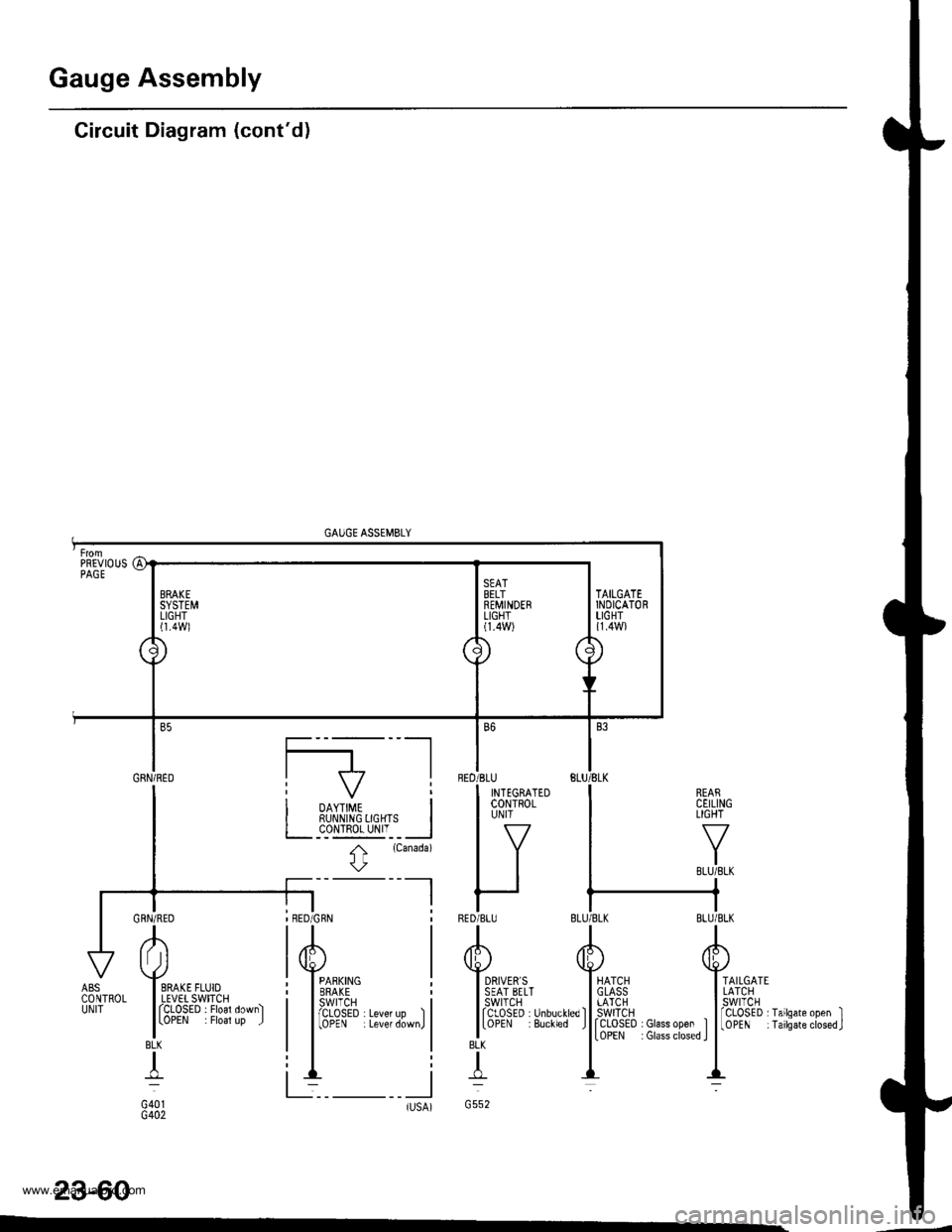
Gauge Assembly
Circuit Diagram (cont'd)
GAUGE ASSEMBLY
REARCEILINGLIGHT
TAILGATELATCHswtTcH
rCLOSED I Glass open ItoPEN : Glass closed I
fCLoSED rTailsate open II0PEN iTailsateclosed.J
23-60
BLK
T
G552tlsA)-
AI Jl
I SRAKE FLUIOI LEVET SWITCHI fCLOSED . Floal down)
lLoPEN . Floal up J
BLK
+
G401G402
ABSCONTROLUNIT
PREVIOUSPAGE
a1
\J
BRAKESYSTEMLIGHTl1.4Wl
\
./
SEATBELTREMINDERLIGHT(1.4W)
\/'
7\
\
TAILGATEINDICATORLIGHT{1.4W}
Gnru;neo I f7 |
I i oo,,#, i| | RUI\N|NG 0GHTS I
I L__c_o!l!g_yI'__l
I t
rcanada)
l\
-l I
BED
RED
B6
'BLU
I INTEGRATEDI coNTRoLI UN|T
lv
IItt
r-IBLU
www.emanualpro.com
Page 1224 of 1395
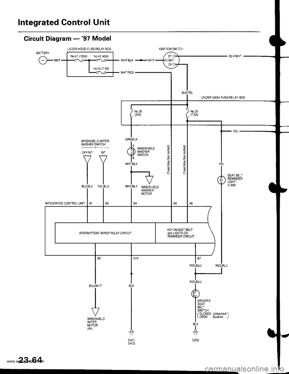
Integrated Gontrol Unit
Circuit Diagram -'97 Model
UNDER.HOOD FUSEi RELAY 8OXBATTEFYI No.4' {'004) \0.d2'40A) |
cr*"
l__*l;;T
w_T ELK +!v_T
I H-uTr.r--i=r-
GFNi BLK
lo,,.h WINDSHIELD( il) WASHEB
Y
SWITCH
WHTiBLK
I
l-IVWHT]BLK WINDSHIELDI WASHERI MOTOB
WINDSHIELD WIPER/WASHEF 9WTTCH ,
OFF/INT INT
VV
tltltl
tl
BLUMHT
VWINDSHIELDWIPERMOTOR(As)
ag
3
YEL
RED/BLU
DRIVER'SSEATBELTswtTcHf CLOSED r Unbuckled )(OPEN :Buckled -.1
BEMINDEBLIGHT(r 4w)
BLK
G401
BL(I-tr-l
G552
23-64
tGNITtON SW lCrl
BLKryEL
KEY.IN/SEAT BELTand LIGHTS-ONBEMINDER CIRCUITNTERMITTENT WIPER RELAY CIRCUlT
www.emanualpro.com
Page 1236 of 1395
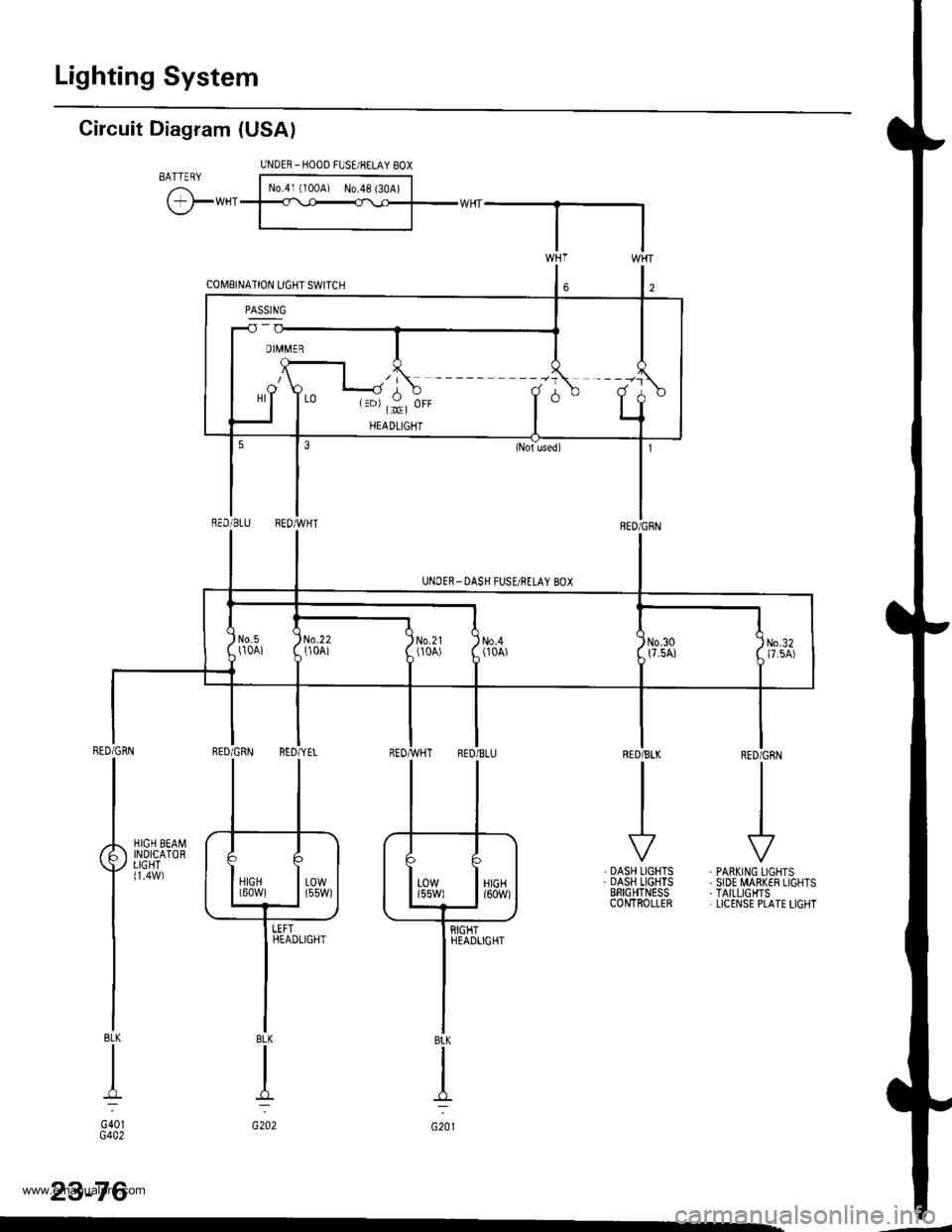
Lighting System
UNOER_HOOD FUSE/RELAY 8OX
Circuit Diagram (USAI
BATTERY
@**'
HIGH SEAI\4INDICATORLIGHT
BLK
I
G40lG4a2
lltl
tl
JJ
VV' DASH LIGHTS , PARKING LIGHTS. DASH LIGHTS . SIDE MARK€R LIGHTSBRIGHTNESS,TAILLIGHTSCOIVTROLLER . LICENSE PLATE TIGHT
rrf JLo -,.9,;,, T d
UNDER-DASH FUSEiREIAY BOX
No.5tl0AlNo.4{10A)N0.3017.5A)
I
li':,.^i
I
IflI
i,"dii Zt'"oll i
II
RED/BLURED'BLK
BLK
.&-
G202
23-76
www.emanualpro.com
Page 1237 of 1395
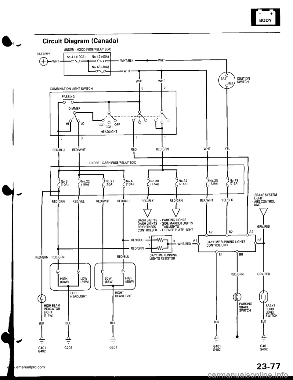
UNDER HOOD FUSEiRELAY 80X
WHT/BLK +WHT
c0t\48rNATroN UGHT SWITCH
4
RED
HIGH BEAMINOICATORLIGHT
l=o) , :., oFF
O,-Circuit Diagram (Canada)
BATTEBY
@*"
UNDER- DASH FUSE/RELAY 8OX
BBAXE SYSTEMLIGHTABS CONTROLUNIT
IIGRN/RED
. DASH LIGHTS ' PARKING LIGHTS, DASH LIGHTS ' SIDE MAHKER LIGHTSERIGHTNESS .TAILLIGHTSCONTHOLLER . LICENSE PLAT€ LIGHT
8LK
d--
G401G402
8LK
-L-::
G40lG402
BLK
I
G20
BLK
I
G202
NEO/CRN
I
T,8LK
I
G401c402
23-77
www.emanualpro.com
Page 1243 of 1395
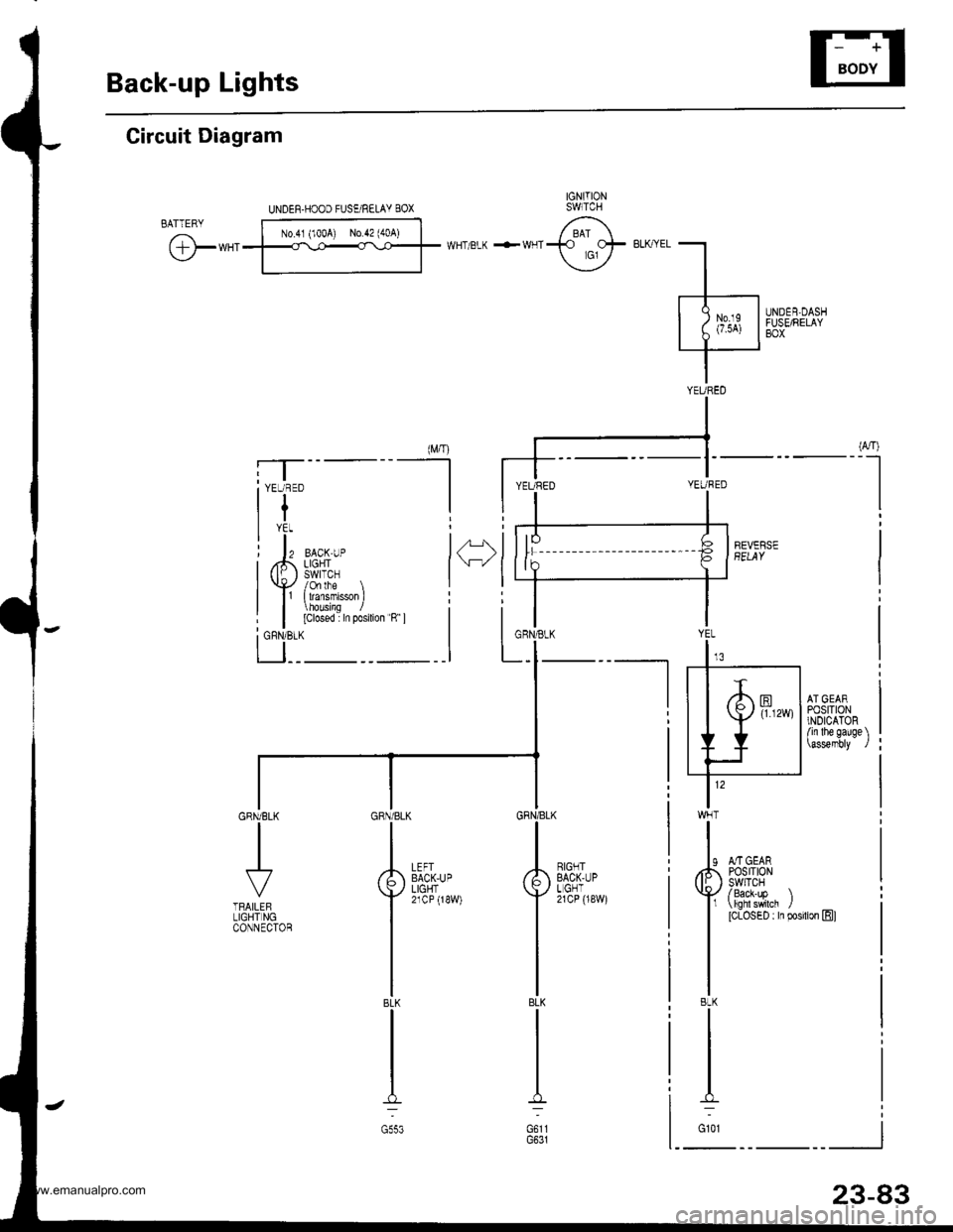
Back-up Lights
Circuit Diagram
(M/r)
I
I
8LK
I
G101
GRN/BLK
I
TBLK
I
UNDEN-HOOD FUSE/RELAY BOX
BACK,UPLIGHTswtTcH/0n1he \I lransmisson J
o!s { /lolosed : In posilion R l
LEFIBACK,UPLIGHT21CP (18W)
*"_,,. _*,,@_ "*"
]__
_..'
iu.Er.w
-r-
RIGHTBACK,UPLGHT21CP 08W)
A,/IGEARPosrl0NswtTcH/Back'up \\l€hl swilch ,/ICLOSED : In posilion [8ll
www.emanualpro.com
Page 1244 of 1395
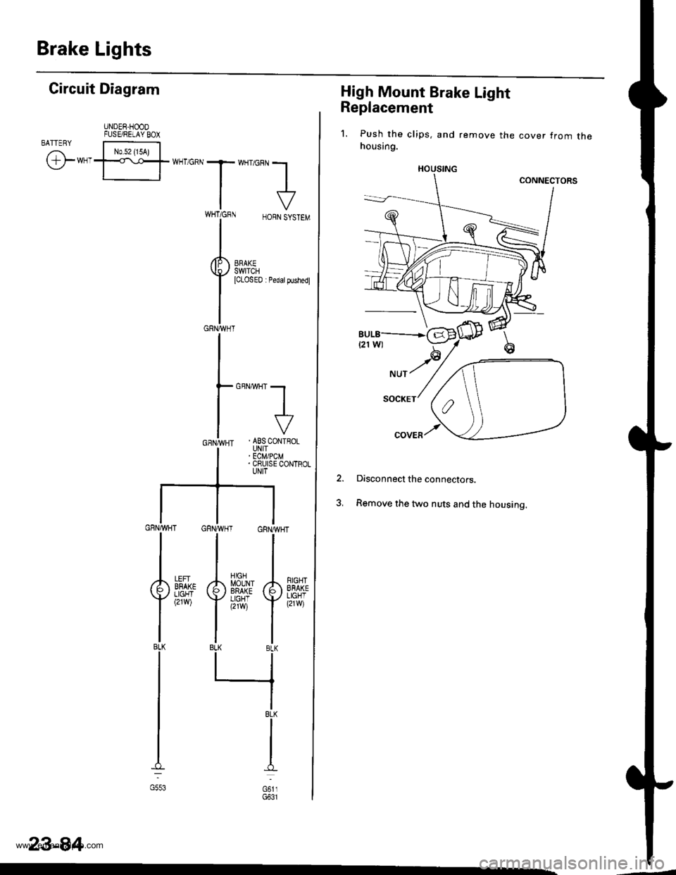
Brake Lights
High Mount Brake Light
Replacement
1. Push the clips, and remove the cover from thehousing.
Disconnect the connectors.
Remove the two nuts and the housing.
2.
HOUSING
Gircuit Diagram
UNDER.HOODFUSE/RELAY BOXBATTENY
/,i | No.s2 {15A) |
\Y*-I=f*-'o*T*'no"l
IV
T:,^-,
HORNSYSTEM
I
i.t53l| *",*"",
GRNA,VHT
GBNMHT -.1
I
I
. ABS CONTFOLUNIT' ECM/PCM. CRUISE CONTROLUNIT
GRNAVHT GRNWH
ll
tl
A[$^Jlr A
Yi,?'il Y
tlBLK BLK
llrl
IBLK
I
I
d
oi,,
RIGHTEFAKELIGHT(21w)
LEFIBFAKELIGHT(2rw)
BLK
G553
23-84
www.emanualpro.com
Page 1245 of 1395
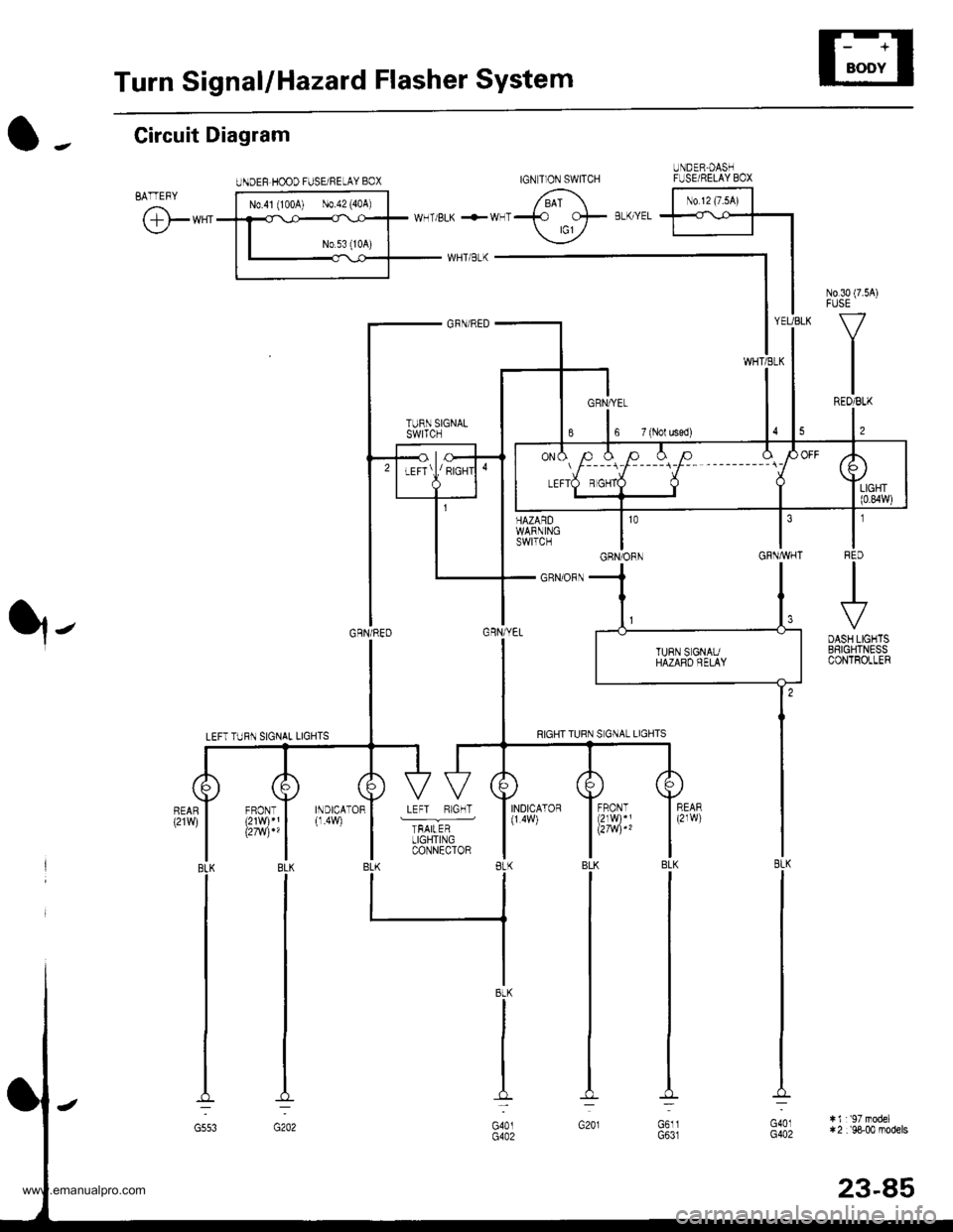
Turn SignallHazard Flasher System
UNDEF HOOD FUSE/NELAY BOX
N0.30 (7.54)FUSE
V
IREO/BLK
l,
t'IFqD
.+
DASH LIGHTSBSIGHTNESSCONTROLLER
HAZARDWARNINGswtTcH
_ GRN/ORN
YEUBLK
WHTiELK
GRNAVHT
O -. Circuit Diagram
BATTEFY
@**'
q-
103
GRN/ORN
INDICATOR
TFAILERLIGHTINGCONNECTOR
INDICATOR(1.4W)
BLK
G553
IGN T]ON SWITCHUNDER.OASHFUSE/RELAY BOX
No 12 (7.sA)
l----r-l-----i-F-- --------_ \
BtK
G401G402
:i1r'97model*2 :'98-00 models
23-85
www.emanualpro.com