Fuel system HONDA CR-V 1999 RD1-RD3 / 1.G Repair Manual
[x] Cancel search | Manufacturer: HONDA, Model Year: 1999, Model line: CR-V, Model: HONDA CR-V 1999 RD1-RD3 / 1.GPages: 1395, PDF Size: 35.62 MB
Page 412 of 1395
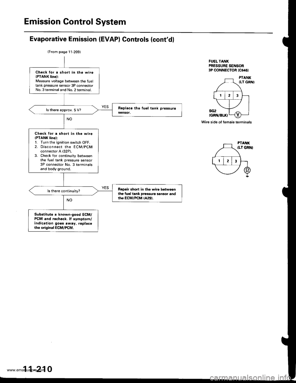
Emission Control System
Evaporative Emission (EVAP) Controls (cont'dl
FUEL TANKPRESSUNE SENSOR3P CONNECTOR tc646l
Wire side of female terminals
(From page l1'209)
Check lor a short in the wireIPTANK Iine}:Measure voltage betlveen the fueltank pressure sensor 3P connectorNo. 3terminal and No. 2terminal.
ls there approx.5 V?
Check for a short in the wire(PTANK line):1. Turn the ignition switch OFF.2. Disco n nect the ECM/PCMconnector A {32P).3. Check for continuity betweenthe fuel tank pressure sensor3P connector No. 3 terminalsand body ground.
Repair short in the wira betwgonthe fuel trnk prossure s6nsor andtho ECM/PCM lA29).
Sub.tituto a known-good ECM/PCM and r€check. lf 3ymptom/indication goer !way. replaceth6 original ECM/PCM.
11-210
www.emanualpro.com
Page 415 of 1395
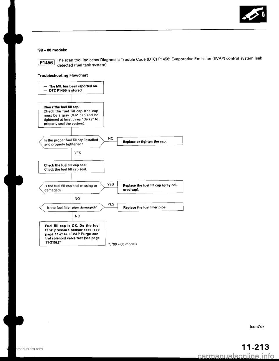
'98 - 00 models:
The scan tool indicates Diagnostic Trouble code (DTC) P1456: Evaporative Emission (EVAP) control system leak
detected {fuel tank system).
Troubleshooting Flowchart
- The MIL has been reported on.- DTC P1456 is stored.
Check the fuel fill cap:Check the fuel fill cap (the caP
must be a gray OEM cap and be
tightened at least three "clicks" toproperly seal the system)-
ls the proper fuel fill cap installed
and properly tightened?Replace or tighton the cap.
Check the lueltill cap seal:
Check the fuel fill cap seal.
Replace the luelfiller pipe.ls the tuel filler pipe damaged?
Fuel till caD is OK. Do the luel
tank pressure Sensor test (see
page 11-2111. (EVAP Purge con-
trol solenoid valve t€sl (see Page11-2151.1r':'99 - 00 models
(cont'd)
11-213
www.emanualpro.com
Page 416 of 1395
Emission Control System
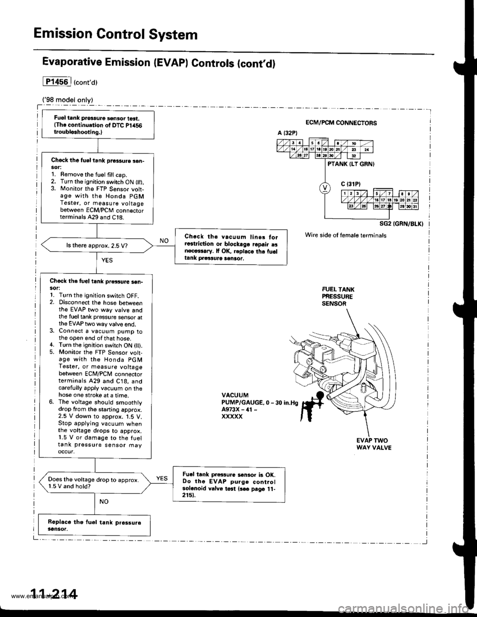
Fuel tank pros3ure sensor tost.(The continuetion of DTC Pl456t.oubls3hooting.,
Chock the tusl trnk pr€3sure sen-sor:1. Remove the fuel fill csp.2. Turn the ignition switch ON fll).3. Monitor the FTP Sensor voh-age with th€ Honda PGMTester, or measure voltagebetween ECM/PCM conn€ctorterminals A29 and C18.
Choct ths vacuum linsr forra3triction o. blockago ropair a!nect*rary. It OK, replaca the fu6ltank praituJc sentot.
ls there approx. 2.5 V?
Check the fuel t nk pressuae 3en-sor:1. Turn the ignition switch OFF.2. Disconnect the hose betweenthe EVAP two way valve andthe tueltank pressure sensor atthe EVAP two way valve end.3. Connect a vacuum pump tothe open end ofthat hose.4. Turn the ignition switch ON 0l).5. Monitor the FTP Sensor volt-age with the Honda PGMTestet, or measure voltagebetween ECM/PCM connectorterminals 429 and C18, andcarefully apply vacuum on thehose one stroke at a lime.6. The voltage should smoothtydrop from the staning approx.2.5 V down to approx. 1.5 V.Stop applying vacuum whenthe voltage drops to approx.1.5 V or damage to the fueltank pressure sensor fiayoccur,
Fu.l tank pressu.c a€nlor b OK.Oo thc EVAP pulge controlsolenoid valve toat (3€€ prgo 11-2151.
Does the voltage drop to approx.1.5 V and hold?
Evaporative Emission (EVAPI Controls (contd)
lP14s6l("ont,a)
ECM/PCM CONNECTORS
SG2 IGRN/BLKI
Wire side oI female terminals
FUEI- TANKPRESSURESENSOR
VACUUMPUMP/GAUGE,0 - 30 in.HgA973X - ill -
xxxxx
EVAP TWOWAY VALVE
11-214
www.emanualpro.com
Page 420 of 1395
Emission Control System
Evaporative Emission IEVAPI Controls (cont'd)
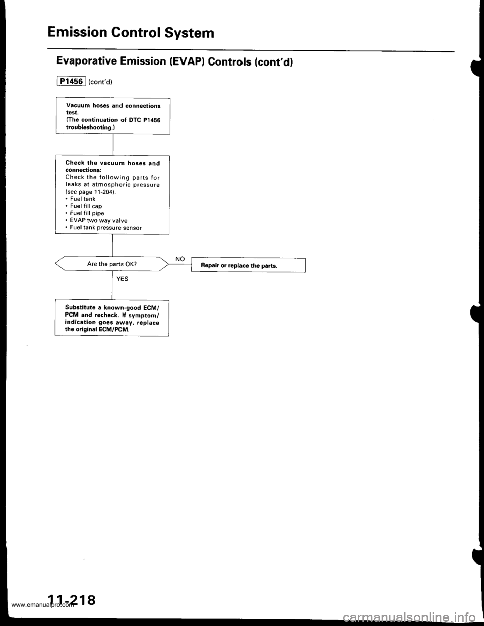
lTi,t56l ("onto)
Vacuum hoses and connectionstelit.(The continuarion of DTC P1456troubleshooiing.l
Check the vacuum ho3es andconnect|ons:Check the following parts forleaks at atmospheric p ressu re{see page 11-204).. Fueltank. Fuel fill cap. Fuelfill pipe. EVAP two way valve. Fueltank pressure sensor
Repair or replaco the parts.
Substitute a known-good ECM/PCM and recheck. lf symptom/indication goes away, replac€the original ECM/PCM.
11-218
www.emanualpro.com
Page 421 of 1395
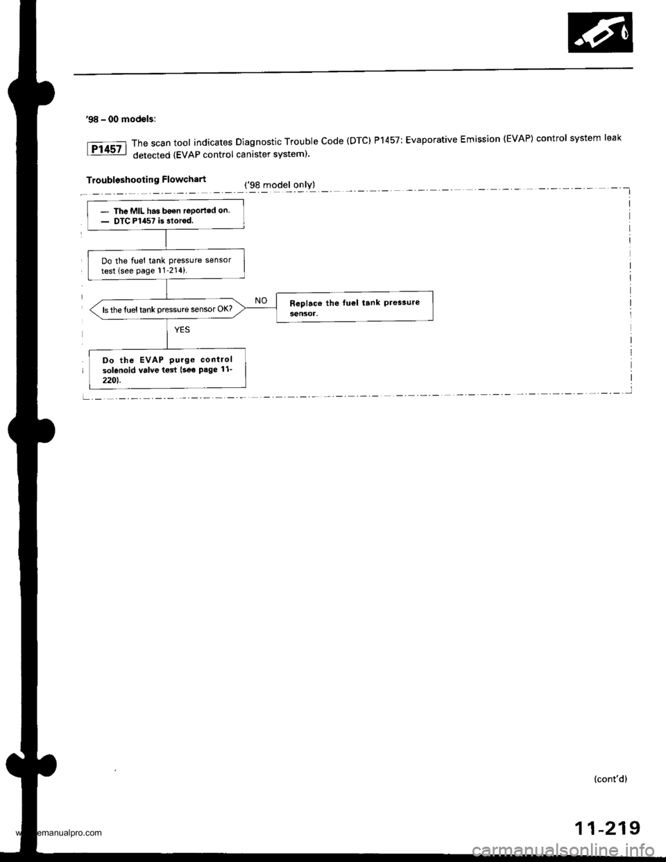
'98 - 00 mod€ls:
The scan tool indicates Diagnostic Trouble code (DTc) P1457: Evaporative Emission (EVAP) Control system leak
detected (EVAP control canister system).
Troubl6shooting Flowchart('98 model only)_]
I
- The MIL has been rePorted on.- DTC P1,157 is storod.
Do the fuel tank Pressure sensor
test {see page 11-214).
ls the {ueltank pressure sensor OK?
Do the EVAP Purge contlol
solenoid valve test lsea Page 1l_
220t.
(cont'dl
11-219
www.emanualpro.com
Page 425 of 1395
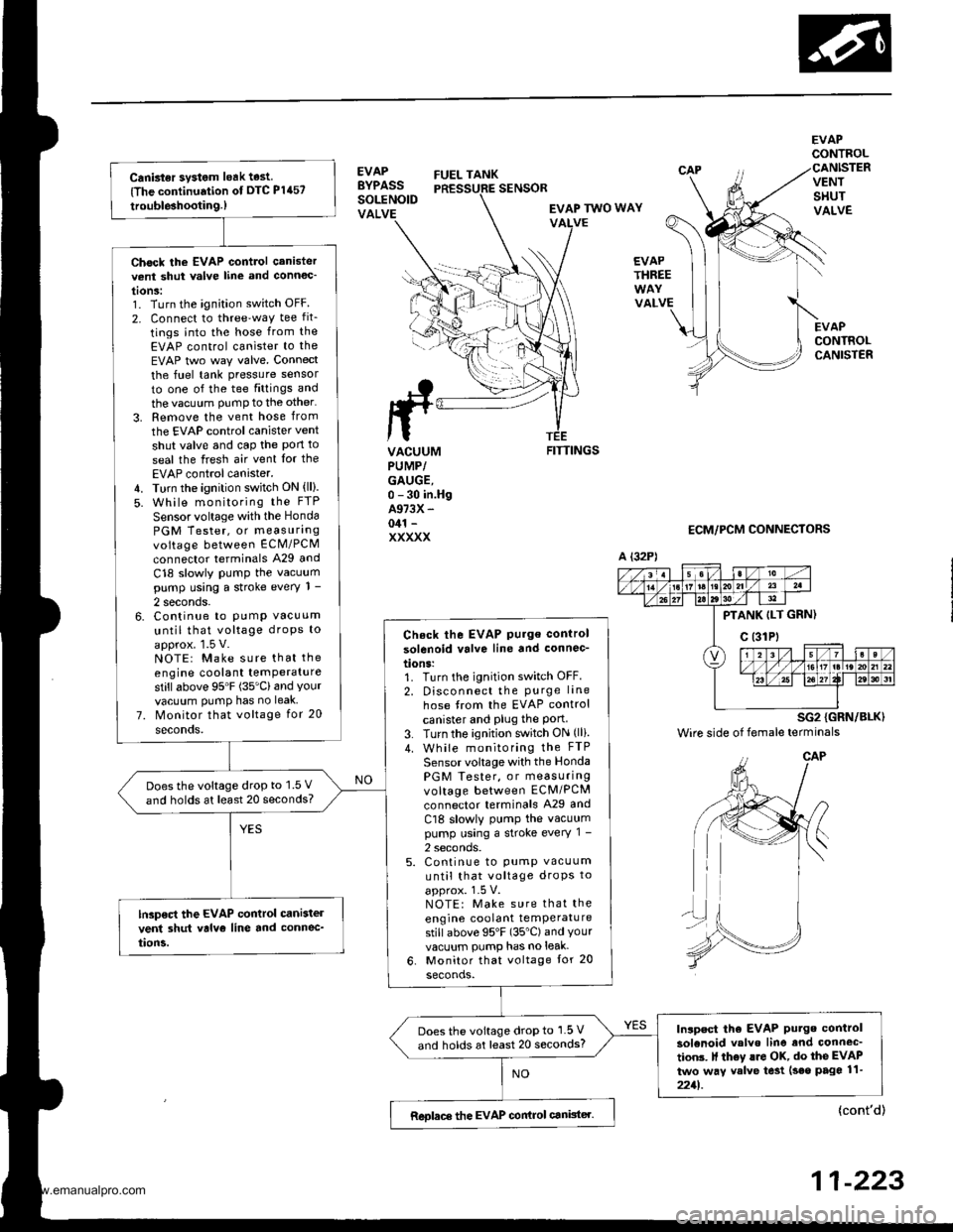
Canbter system leak test
{The continuation of DTC P1457
trouble3hootin9.)
Chock the EVAP control canistervent shut valve line and connoc'
tonS:1. Turn the ignition switch OFF
2. Connect to three'way tee fit_
tings into the hose from the
EVAP control canister to the
EVAP two way valve. Connect
the fuel tank pressure sensor
to one of the tee fittings and
the vacuum PumP to the other'
3. Remove the vent hose from
the EVAP control canister vent
shut valve and cap the Pon to
seal the fresh air vent Ior the
EVAP control canister.4. Turn the ignition switch ON (ll).
5. While monitoring the FTP
Sensor voltage with the Honda
PGM Tester, or measurangvoltage between ECM/PCM
connector terminals A29 and
C18 slowly PumP the vacuumpump using a stroke every 1 -
2 seconds.6. Continue to PumP vacuum
until that voltage droPs to
approx. 1.5 V.NOTE: Make sure that the
engine coolant temPeraturestillabove 95'F (35'Cland Yourvacuum PumP has no leak
7. Monitor that voltage for 20
seconds.
Check the EVAP Pu.ge control
solenoid valve line and connec-
tions:1. Turn the ignition switch OFF.
2. Disconnect the Purge lane
hose from the EVAP control
canister and Plug the Port3. Turn the ignition switch ON (lli.
4. While monitoring the FTP
Sensor voltage with the Honda
PGM Tester, or measuringvoltage between ECM/PCM
connector terminals A29 and
Cl8 slowly PumP the vacuumpump using a stroke every 1 -
2 seconds.5. Continue to pump vacuum
until that voltage droPs to
approx. 1-5 V.NOTE: Make sure that the
engine coolant temPeraturestill above 95'F (35"C) and Yourvacuum pump has no leak-
6. Monitor that voltage tor 20
seconds.
Doesthe voltage drop to 1.5 V
and holds at least 20 seconds?
lGp€ct the EVAP control cani3tel
vent 3hut valvo line and connec_
tion5.
Inlpect tho EVAP Putge control
solenoid valvo line and connec'
tion3. It th6y lro OK, do the EVAP
two way valve te3t (seo page 11-
2211.
Does the voltage drop to 1.5 V
and holds at least 20 seconds?
Reolace the EVAP conirol canister.
EVAPBYPASSSOLENOIDVALVE
FUEL TANK
EVAPCONTROL
VENTSHUTVALVE
EVAPCONTROLCANISTER
SENSOR
EVAP TWO WAYVALVE
EVAPTHREE
VALVE
ttrrL
ta
VACUUMPUMP/GAUGE,0 - 30 in.HgA973X -
041 -
XXXXX
FITTINGS
ECM/PCM CONNECTORS
A {32P)
PTANK ILT GRN)
c (31Pt
SG2 {GRN/BLK)
Wire side of female terminals
{cont'd)
11-223
www.emanualpro.com
Page 426 of 1395
Emission Control System
Evaporative Emission (EVAP) Controls (cont,dl
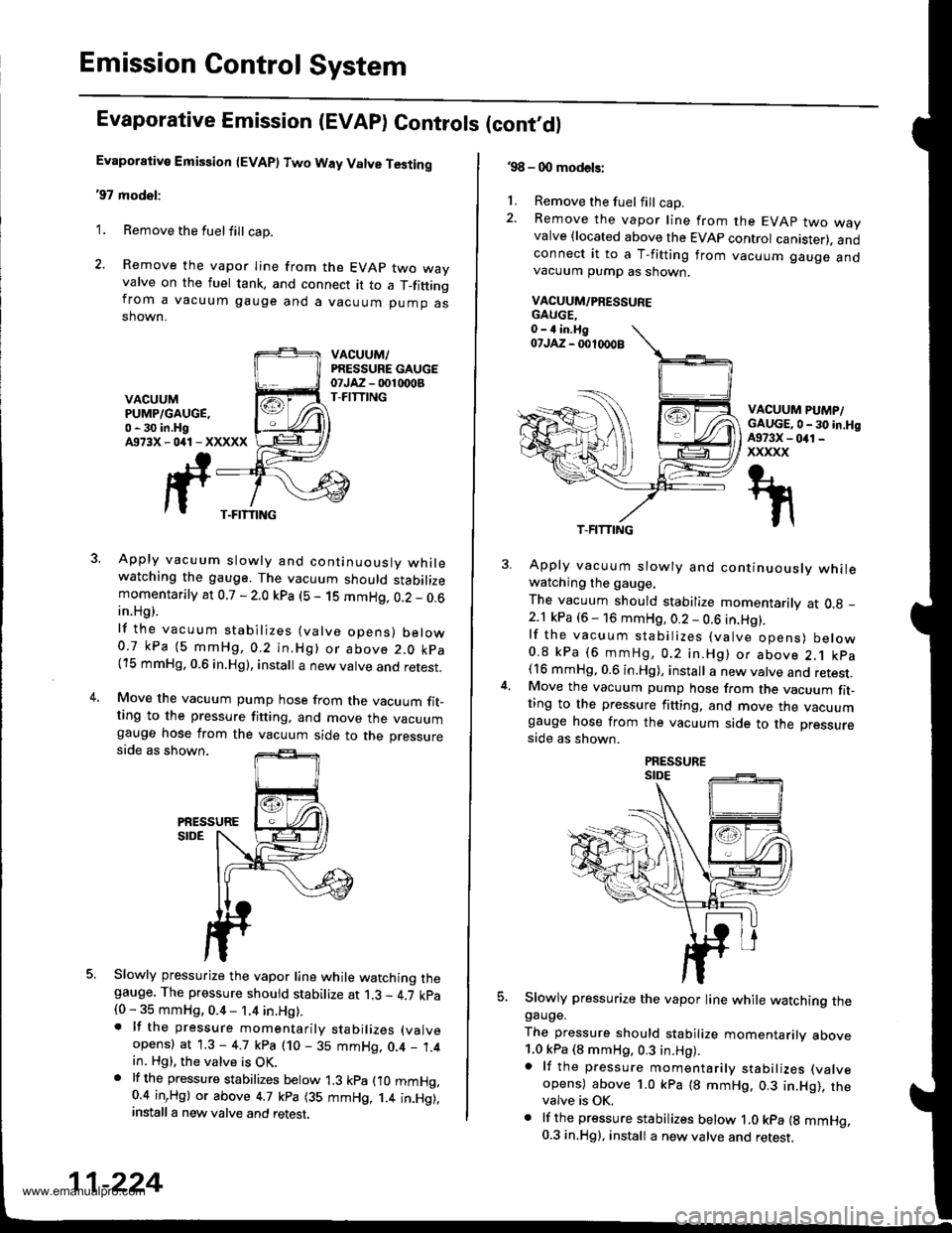
Evaporative Emission (EVAP) Two Way Valve Testing
'97 model:
1. Remove the fuelfill cap.
2. Remove the vapor Iine from the EVAP two wayvalve on the fuel tank, and connect it to a T_fittingfrom a vacuum gauge and a vacuum pump asshown.
VACUUM,/PRESSURE GAUGEotJAz - 001 rDoBT-FITTINGVACUUMPUMP/GAUGE,0 - 30 in.HgA973X-041-XXXXX
3. Apply vacuum slowly and continuouslv whilewatching the gauge. The vacuum should stabilizemomentarily at 0.7 - 2.0 kpa (5 - 1S mmHg, 0.2 _ 0.6in.Hg).
lf the vacuum stabilizes (valve opens) below0.7 kPa (5 mmHg,0.2 in,Hg) or above 2.0 kpa(15 mmHg, 0.6 in.Hg), install a new valve and retest.
4.Move the vacuum pump hose from the vacuum fit_ting to the pressure fitting, and move the vacuumgauge hose from the vacuum side to the pressureside as shown.
PiESSURESIDE
5. Slowly pressurize the vapor line while watching thegauge. The pressure should stabilize at 1.3 - 4.7 kpa(0 - 35 mmHg, 0.4 - 1.4 in.Hg).. lf the pressure momentarily stabilizes (valve
opens) at 1.3 - 4.7 kpa (10 - 35 mmHg, 0.4 _ 1.4in. Hg), the valve is OK.. lf th6 pressure stabilizes below 1.3 kpa fio mmHg,0.4 inrHg) or above 4.7 kpa (35 mmHg, 1.4 in.Hg),install a new valve and retest.
T-FITTING
11-224
.98 - 0O models:
1. Remove the fuel fill cap.2. Remove the vapor line from the EVAP two wayvalve {located above the EVAP control canister). andconnect it to a T-fitting from vacuum gauge andvacuum pump as shown.
VACUUM/PRESSUFE
VACUUM PUMP/GAUGE,0 - 30 in.HgA973X - 041 -
xxxxx
5.
Apply vacuum slowly and continuously whilewatching the gauge.
The vacuum should stabilize momentarily at O.g _
2.1 kPa (6 - 16 mmHg, 0.2 - 0.6 in.Hg).lf the vacuum stabilizes (valve opens) below0.8 kPa (6 mmHg, 0.2 in.Hg) or above 2.1 kpa(16 mmHg, 0.6 in.Hg), install a new valve and retest.Move the vacuum pump hose from the vacuum fit-ting to the pressure fitting. and move the vacuumgauge hose from the vacuum side to the pressure
side as shown.
Slowly pressurize the vapor line while watching thegauge.
The pressure should stabilize momentarilv above1.0 kPa (8 mmHg, 0.3 in.Hg).a lf the pressure momentarily stabilizes (valve
opens) above 1.0 kPa (8 mmHg. 0.3 in.Hg), thevalve is OK.. lf the pressure stabilizes below ,|.0 kpa {g mmHg.0.3 in.Hg), install a new valve and retest.
T-FITTING
www.emanualpro.com
Page 572 of 1395
Troubleshooting Procedures
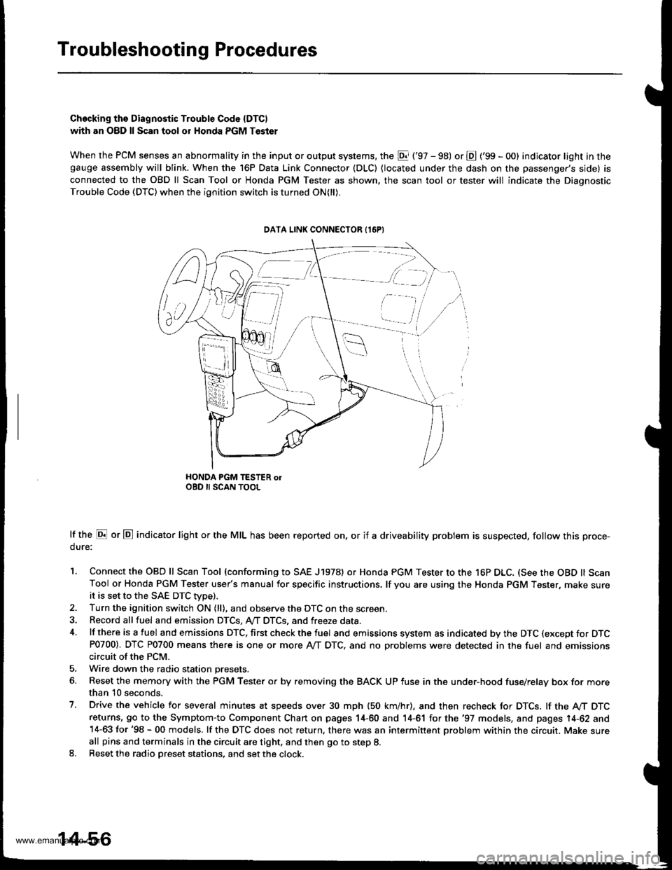
Checking ths Diagnostic Trouble Code (DTC)
with an O8D ll Scan tool or Honda PGM Tsster
When the PCM senses an abnormality in the input or output systems, the El ('97 - 98) or E ('99 - O0) indicator light in thegauge ass€mbly will blink. When the 16P Data Link Connector (DLC) {located under the dash on the passenger's side) is
connected to the OBD ll Scan Tool or Honda PGM Tester as shown, the scan tool or tester will indicate the Diagnostic
Trouble Code (DTC) when the ignition switch is turned ON(ll).
HONDA PGM TESTER olOBD II SCAN TOOL
lf the E or E indicator light or the MIL has been reported on, or if a driveability problem is suspected, follow this proce-
dure:
1. Connect the OBD ll Scan Tool (conforming to SAE J1978) or Honda PGM Tester to the 16P DLC. (See the OBD ll ScanTool or Honda PGM Tester user's manual for specific instructions. lf you are using the Honda PGM Tester, make sureit is set to the SAE DTC Wpe).2. Turn the ignition switch ON (ll), and observe the DTC on the screen
3. Record allfuel and emission DTCS, A,,/T DTCS, and freeze data.
4. lf there is a fuel and emissions DTC, first check the fuel and emissions system as indicated by the DTC (except for DTCP0700). DTC P0700 means there is one or more Ay'T DTC, and no Droblems were detected in the fuel and emissionscircuit of the PCM.
5. Wire down the radio station presets.
6. Reset the memory with the PGM Tester o. by removing the BACK UP fuse in the under-hood fuse/relay box for morethan 10 seconds.
7. Drive the vehicle for several minutes at speeds over 30 mph (50 km/hr), and then recheck for DTCS. lf the A/T DTCreturns, 9o to the Symptom-to Component Chart on pages 14-60 and 14-61 for the '97 models, and pages 14-62 and14-63 for '98 - 00 models. lf the OTC does not return, there was an intermittent problem within the circuit. Make sureall pins and terminals in the circuit are tight, and then go to step 8.8. Reset the radio Dreset stations, and set the clock.
DATA LINK CONNECTOR {16PI
[ -=.r,
ili,i /i,
v,., i
14-56
www.emanualpro.com
Page 1141 of 1395
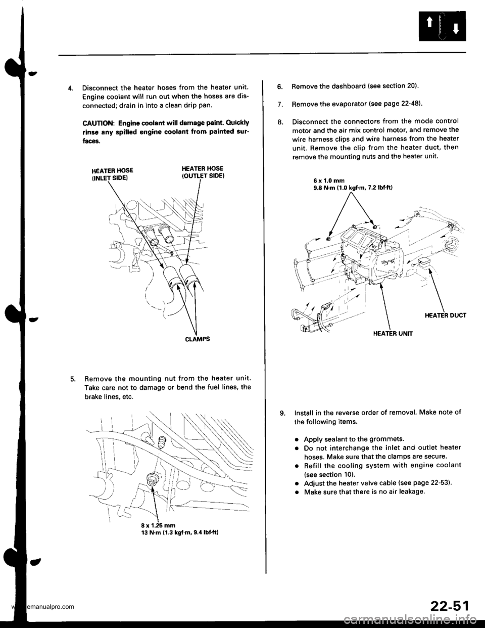
4. Disconnect the heater hoses from the heater unit.
Engine coolant will run out when the hoses are dis-
connected; drain in into a clean drip pan.
CAUTION: Engino coolant will damage p8int. Ouickly
rinse any spill€d engine coolant Itom painted sur-
faces.
HEATER HOSEIOUTLET SIDE)
Remove the mounting nut from the heater unit.
Take care not to damage or bend the fuel lines, the
brake lines. etc.
CLAMPS
13 N.m 11.3 kg{.m,9.4 lbtftl
22-51
7.
ll.
Remove the dashboard (see section 20).
Remove the evaporator (see page 22-48).
Disconnect the connectors from the mode control
motor and the air mix control motor, and remove the
wire harness clips and wire harness from the heater
unit. Remove the clip from the heater duct, then
remove the mounting nuts and the heater unit
6x1.0mm9,8 N.m (1.0 kgt m,7.2lblft)
qInstall in the reverse order of removal. Make note of
the following items.
a
a
a
a
Apply sealant to the grommets.
Do not interchange the inlet and outlet heater
hoses. Make sure that the clamps are secure.
Refill the cooling system with engine coolant
{see section 10).
Adiust the heater valve cable (see page 22-53).
Make sure that there is no air leakage.
HEATER UNIT
www.emanualpro.com
Page 1161 of 1395

Body Electrical
Speciaf Toofs ,...,..,.............-.23-2
Troubleshooting
Tips and Precautions ......,.,..........,.................. 23-3
Five-step Troubleshooting ........,.,.,...,,.,......... 23-5
Wire Color Codes ...,....,.. 23-5
Relay and Control Unit Locations
Engine Compartment ..,.,......,......................... 23-6
Dashboard ,.,.,..............-.- 23-7
Door ....................... .........23-10
Index to Cilcuits and Sysiems
Accessory Socket .. ,....,.,..,.,. 23-95*Airbags ................ .,....,. Sestion 24
Air Conditioning ,.,.,.... Section 22
Alternator ................... Section 4
Anti-lock Brake System {ABSI ................... Section 19'A/T Gear Position Indicator ....................... Section 1,1
Automatic Transmission System ...........,.. Section 14
Battery ................... ..............23-50
Blower Controls .,...,.,, Section 22
Charging System ....... Seqtion il
Clock -'98 Model ................ 23-98
Connector ldentification and Wire HarnessRouting .................. ......... 23.11
Cruise Control ............ Ssction 4
Dash Lights Brightness Contlo||er ..................... 23-90
Fan Conlrols ...,......,.... Section 10
Fuel Pump ,..,.,...,....,.... Section 11
Fuses...................... .,,.,.,.,.,,.,23-40*Gauges
Circuit Diagram ......-....-..23-58
Fuel Gauge .....,.,..... Section 11
Speedometer ..,..........,... 23-56
Ground Distribution ,....,.,...23-46
Hatch Glsss ODenor .........................,.,.,.,.,..,.,.,.,,. 23-121
Heater Controls .-........ Soction 21*Horns.,...,..,.,.,....... ................23"104*fgnition Switch ,,.,.,..,.,.,,.,.,.,23-51
lgnition Key Light System -'97 Mod6l .............. 23.88
-+
BODY
www.emanualpro.com