Bolt HONDA CR-V 1999 RD1-RD3 / 1.G Repair Manual
[x] Cancel search | Manufacturer: HONDA, Model Year: 1999, Model line: CR-V, Model: HONDA CR-V 1999 RD1-RD3 / 1.GPages: 1395, PDF Size: 35.62 MB
Page 447 of 1395
Transmission Assembly
Removal (cont'dl
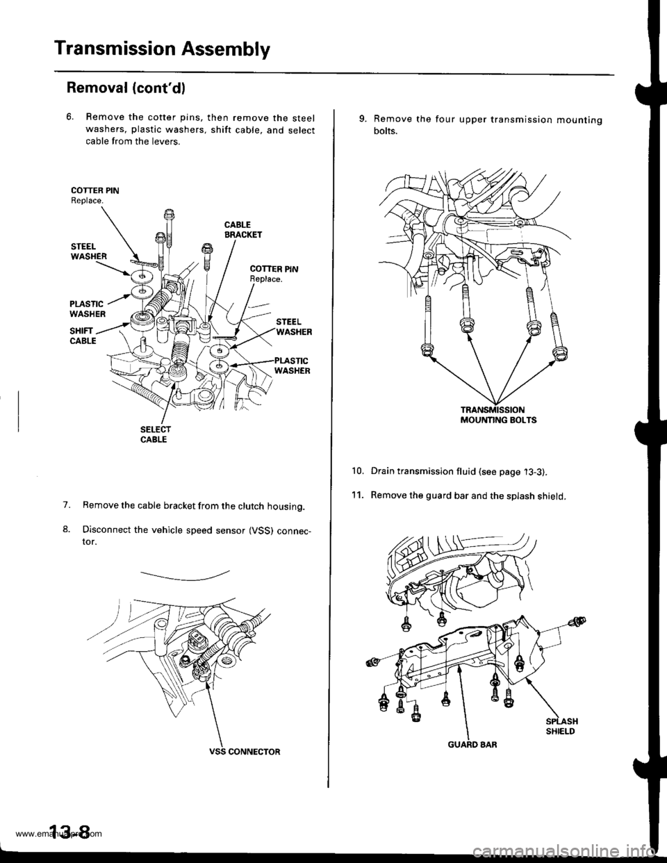
6. Remove the cotter pins,
washers, plastic washers.
cable from the levers.
then remove the steel
shift cable, and select
1.
8.
Remove the cable bracket from the clutch housing.
Disconnect the vehicle speed sensor (VSS) connec-tor.
-------------.2
13-8
9. Remove the
bolts.
four upper transmission mou nting
10.
11.
Drain transmission fluid (see page '13-3).
Remove the guard bar and the splash shield.
MOUNNNG BOLTS
www.emanualpro.com
Page 448 of 1395
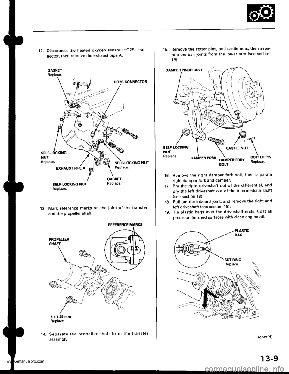
12. Disconnect the heated oxygen sensor (HO2S) con-
nector, then remove the exhaust pipe A.
GASKETReplace.
HO2S CONNECTOR
NUTReplace.
EXHAUST
SELF.LOCKINGReplace.
GASKETReplace.
Mark reference marks on the joint of the transfer
and the propeller shaft.
8 x 1.25 mmReplace.
Separate the propeller shaft from the transfer
assemDly.
REFERENCE MABKS
14.
15. Remove the cotter pins, and castle nuts. then sepa-
rate the ball ioints from the lower arm (see sectlon
18).
OAMPER PINCH BOLT
CASTLE NUTNUTReplace.
17.
16.
DAMPER FORKFOFKEOLTReplace.
Remove the right damper tork bolt, then separate
right damper fork and damPer.
Pry the right driveshaft out of the differential, and
pry the left driveshaft out of the intermediate shaft
(see section 18).
Pull out the inboard ioint, and remove the right and
left driveshaft (see section 18).
Tie plastic bags over the driveshatt ends. Coat all
precision finished surfaces with clean engine oil
18.
19.
\
{cont'd}
13-9
www.emanualpro.com
Page 450 of 1395
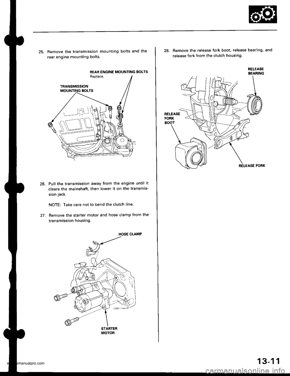
25. Remove the transmission mounting bolts and the
rear engine mounting bolts.
REAR ENGINE MOUNTING BOLTSReplace.
TRANSMISSION
Pull the transmission away from the engine until it
clears the mainshaft, then lower it on the transmis-
sion jack.
NOTE: Take care not to bend the clutch line.
Remove the starter motor and hose clamp from the
transmission housing.
STARTERMOTOR
28. Remove the release tork boot. release bearing, and
release fork from the clutch housing
RELEASEBEANING
13-1 1
www.emanualpro.com
Page 452 of 1395
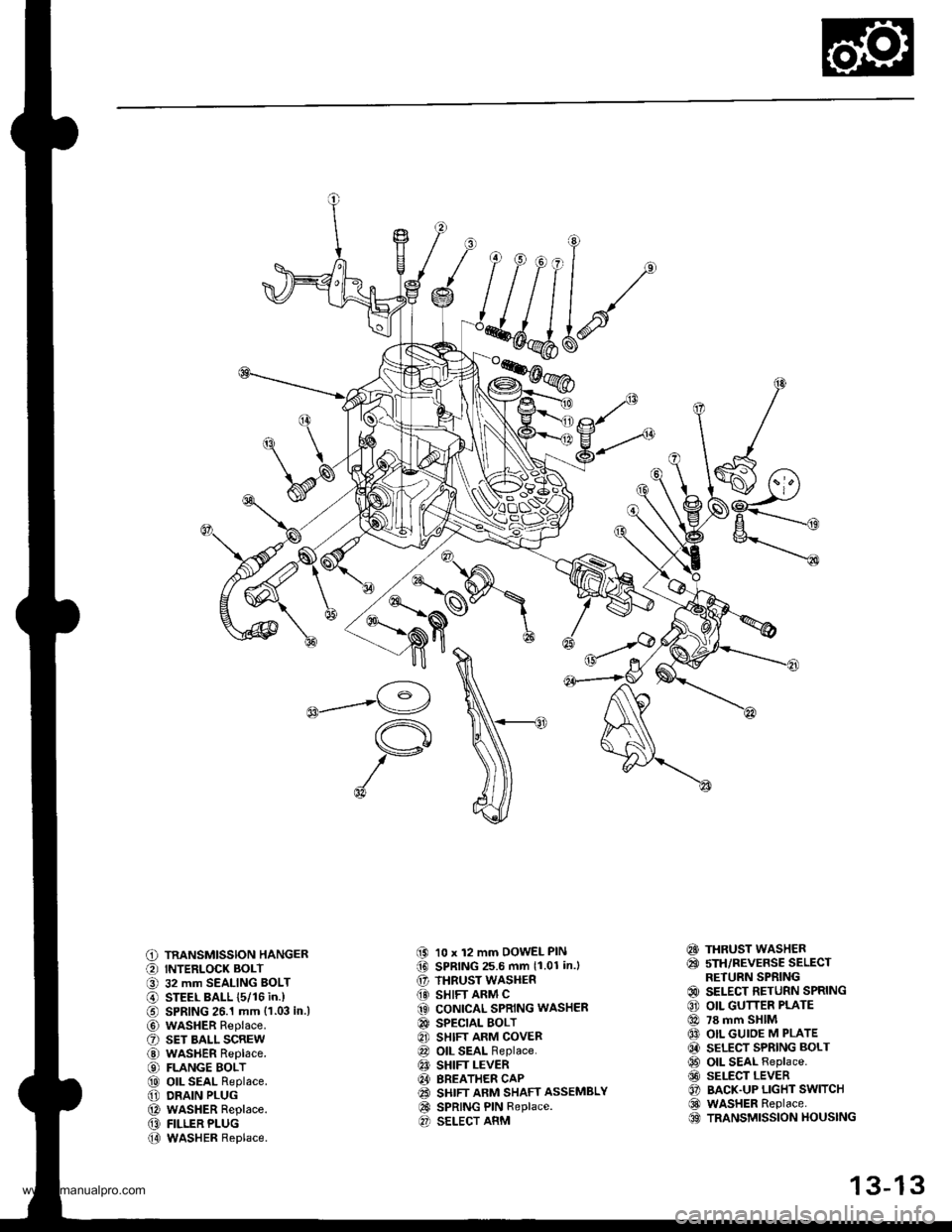
C) TRANSMISSION HANGER
O INTERLOCK BOLT
O 32 mm SEALING BOLT
@ STEEL BALL {5/16 in.)
€) SPRING 26.1 mm {1.03 in.l
@ wasHER Replace.
O sET BALL scREw
@ WASHER Replace.
€) FLANGE BOLT
@ oll SEAL Replace.
@ DRAIN PLUG
@ WASHER Replace.
@ FILLER PLUG
@ WASHER Replace.
(9 10 x 12 mm DOWEL PIN(D SPRING 25.6 mm 11.01 in.l
€' THRUST WASHER
@} SHIFT ARM C(3 CONICAL SPRING WASHER
@ SPECTAL BOLT
8] SHIFT ARM COVER
@ OIL SEAL Replace.
€! SHIFT LEVER
@I BREATHER CAP(2! SHIFT ARM SHAFT ASSEMBLY
@ SPRING PIN Replace.O SELECT ARM
€!} THRUST WASHER
@ sTH/REVERSE SELECTRETURN SPRING
@ SELECT RETURN SPRING
€) OIL GUTTER PLATE
@ 78 mm SHIM
@ OIL GUIOE M PLATE
@ SELECT SPRING BOLT
@ OIL SEAL Replace.
@ SELECT LEVER
O BACK.UP LIGHT SWITCH
@ WASHER Replace.OO TRANSMISSION HOUSING
13-13
www.emanualpro.com
Page 453 of 1395
Transmission Assembly
Disassembly
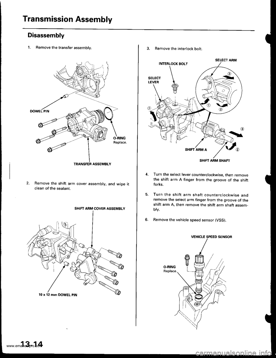
1. Remove the transfer assemblv.
O-RINGReplace.
Remove the shift arm cover assembly, and wiDe itclean of the sealant.
SHIFT ARM COVER ASSEMBLY
10 x 12 mm DOWEL ptN
13-14
3. Remove the interlock bolt.
SELECT ARM
SHIFT ARM SHAFT
Turn the select lever counterclockwise, then removethe shift arm A finger from the groove of the shiftforks.
Turn the shift arm shaft counterclockwise andremove the select arm finger from the groove of theshift arm A. then remove the shift arm shaft assem-blv.
Remove the vehicle speed sensor (VSS).
5.
6.
www.emanualpro.com
Page 454 of 1395
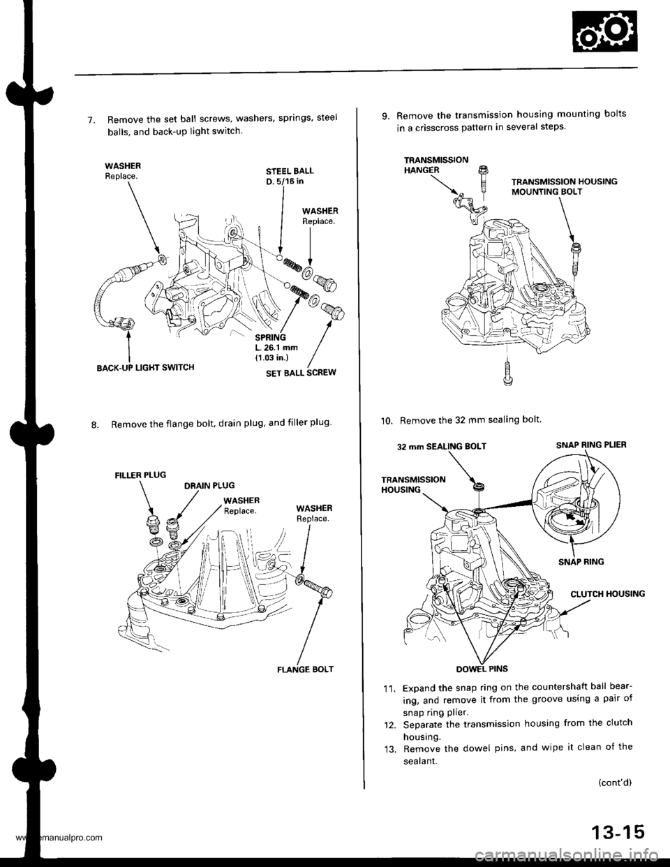
7. Remove the set ball screws, washers, springs, steel
balls. and back-uP light switch.
STEEL BALLD. 5/16 in
8. Remove the flange bolt. drain plug, and filler plug
DRAIN PLUG
WASHERReplace.
LIGHT SWITCH
FILLER PLUG
WASHERReplace.
FLANGE BOLT
9. Remove the transmission housing mounting bolts
in a crisscross pauern in several steps.
10. Remove the 32 mm sealing bolt
Expand the snap ring on the countershaft ball bear-
ing, and remove it from the groove using a pair of
snap ring plier.
Separate the transmission housing from the clutch
housing.
Remove the dowel pins, and wipe it clean of the
sealant.
'I t.
(cont'd)
13-15
www.emanualpro.com
Page 455 of 1395
Transmission Assembly
Disassembly (cont'dl
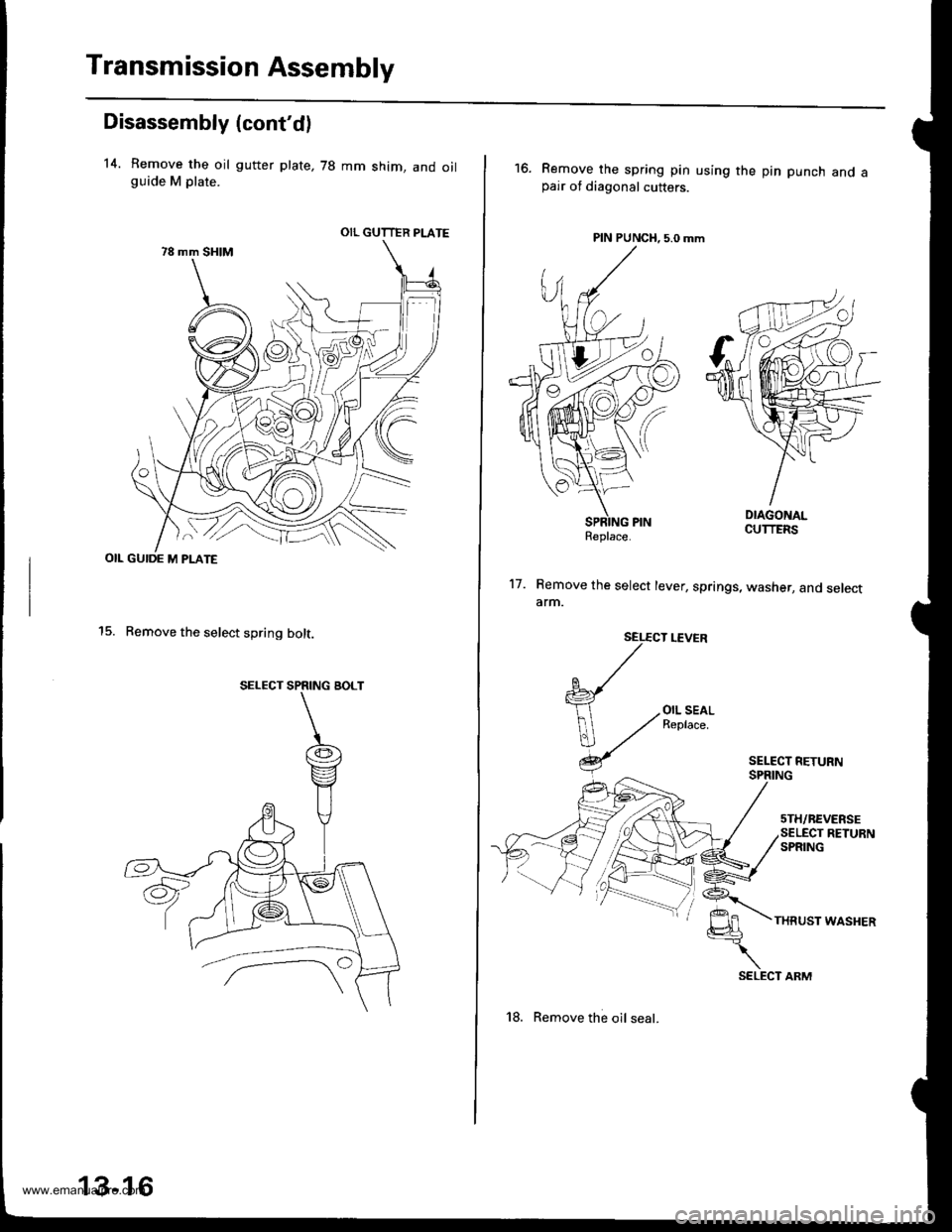
14. Remove the oil gutter plate, 78 mm shim, and oilguide M plate.
OIL GUIDE M PLATE
15. Remove the select spring bolt.
OIL GUTTER PLATE
SELECT SPRING BOLT
13-16
18. Remove the oil seal.
16.Remove the spring pin using the pin punch and apair of diagonal cutters.
PIN PUNCH, 5.0 mm
17. Remove the select lever, springs, washer, and selectarm.
SEL€CT LEVER
{
V
OIL SEALReplace.
THRUST WASHER
Replace.
SELECT ARM
www.emanualpro.com
Page 457 of 1395
Shift Arm Cover/Shift Arm Shaft Assembly
Disassembly/Reassembly
Shift Arm Cover Ass€mbly
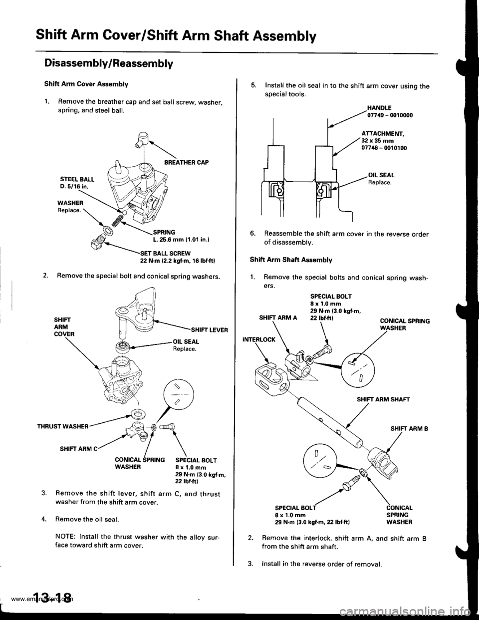
1. Remove the breather cap and set ball screw, washer,
spring. and steel ball.
BREATHER CAP
SPRINGL,25.6 mm (1.01 in.l
T BALL SCREW22 N.m 12.2 kgtm, 16lbf.ftl
Remove the special bolt and conical spring washers.
SHIFTARMCOVER
THRUST WASHER
SHIFI ARM C
WASHER 8x1.0mft
SHIFT LEVER
29 N.m 13.0 kg{.m,z2 tbt.ftl
arm C, and thrustRemove the shift lever, shift
washer from the shift arm cover.
Remove the oil seal.
NOTE: lnstall the thrust washer
face toward shift arm cover.
STEEL BALLD. 5/16 in,
13-18
with the alloy sur-
3. Install in the reverse order of removal.
5. Install the oil seal in to the shift arm cover usino thesDecialtools.
HANOLE07749 - 0010000
ATTACHMENT,32x35mm077a6 - 0010100
OIL SEALReplace.
6. Reassemble the shift arm cover in the reve.se order
of disassembly.
Shift Arm Shaft Assembly
1. Remove the special bolts and conical spring wash-
ers.
SPCCIAL BOLT8x1.0mm29 N.m (3.0 kgf.m,SHIFTARMA 22IbI.ftICONICAL SPRING
SHIFT ARM SHAFT
SPECIAL BOLT8x1.0mm29 N.m {3.0 kgf.m, 22 lbtft}
2. Remove the interlock, shift
from the shift arm shaft.
SPRINGWASHER
arm A, and shift arm B
www.emanualpro.com
Page 478 of 1395
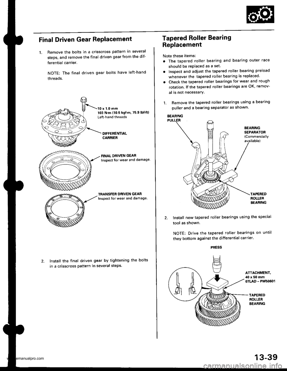
Final Driven Gear RePlacement
LRemove the bolts in a crisscross pattern in several
steps, and remove the final driven gear from the dif-
ferential carrier.
NOTE: The final driven gear bolts have left-hand
threads.
10 x 1.0 mm103 N.m (10.5 kgf m,75.9lbf'ftlLeft'hand threads
FINAL DRIVEN GEAR
lnsoect {or weal and damage
TRANSFER ORIVEN GEARInspect for wear and damage.
Install the final driven gear by tightening the bolts
in a crisscross pattern in several steps.
Tapered Roller Bearing
Replacement
Note these items:
. The tapered roller bearing and bearing outer race
should be replaced as a set.
. Inspect and adiust the tapered roller bearing preload
whenever the tapered roller bearing is replaced'
. Check the tapered roller bearings for wear and rough
rotation. lf the tapered roller bearings are OK, remov-
al is not necessary.
1. Remove the tapered roller bearings using a bearing
puller and a bearing separator as shown.
Install new tapered roller bearings using the special
tool as shown.
NOTE: Drive the tapered roller bearings on until
they bottom against the differential carrter.
PRESS
IJ
BEARINGSEPAFATOB{Commercially
ATTACHMENT,,10 x 50 mm07LAD - PWs060 l
BEARING
13-39
www.emanualpro.com
Page 502 of 1395
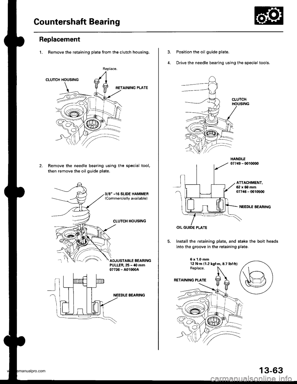
Gountershaft Bearing
Replacement
1. Remove the retaining plate from the clutch housing.
CLUTCH HOUSING
HETAINING PLATE
Remove the needle bearing using the special tool,
then remove the oil guide plate.
Replace.
3/8" -16 SLIDE HAMMER(Commercially available)
CLUTCH TIOUSING
^'ADJUSTABI.f BEARINGPULLER,25 - 40 mm07736 - A01(x)04
NEEDLE BEARING
Position the oil guide plate.
Drive the needle bearing using the special tools.
ATTACHMENT,62x88mm07746- 0t!105q)
NEEDII AEARING
Install the retaining plate, and stake the bolt heads
into the groove in the retaining plate
6x1.0mm12 N.m (1.2 kgt m,8.7 lbtftl
13-63
www.emanualpro.com