Shift solenoid HONDA CR-V 1999 RD1-RD3 / 1.G Repair Manual
[x] Cancel search | Manufacturer: HONDA, Model Year: 1999, Model line: CR-V, Model: HONDA CR-V 1999 RD1-RD3 / 1.GPages: 1395, PDF Size: 35.62 MB
Page 778 of 1395
Transmission
Installation (cont'dl
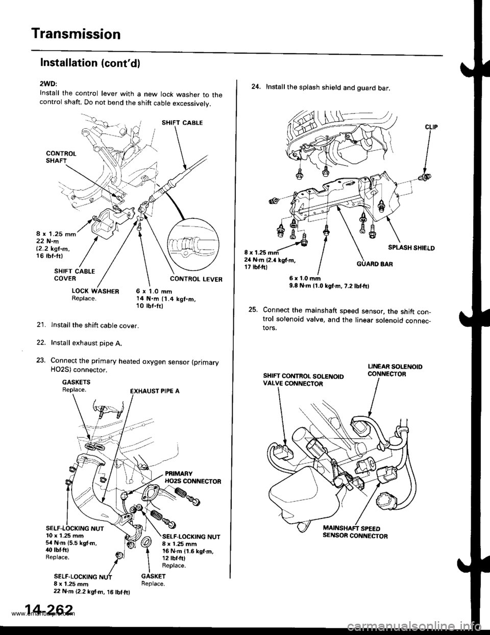
2WD:
Install the control lever with a new lock washer to thecontrol shaft. Do not bend the shift cable excessivelv.
8 r 1.25 mm22 N.m|'2.2 kgt.m,16 rbf.ft)
SI{IFT CAELECOVER
LOCK WASHER 6 x 1.0 mmReplace. 14 N.m 11.4 kgt.m,10 tbr.frl
lnstallthe shift cable cover.
Install exhaust pipe A.
Connect the primary heated orygen sensor (primary
HO2S) connector.
GASKETSReplace.
22.
23.
10 x 1.25 m.n5r N.m {5.5 kgf.m,40 tbtftlReplace.
SELF.LOCKING
SELF-LOCKING NUT8 ! 1.25 mm16 N.m {1.6 kgf.m,12 lbf.fttReplace.
8 x 1.25 mm22 N.m {2,2 kgt.m, l5 lbt.ftl
SHIFT CABLE
14-262
24. Installthe splash shield and guard bar,
8 x 1.2524 N.m {2.a kgl.m,17 tbt.ftl
SPLASH SHIELD
GUARO BAR
25.
6r1.0|r|m9.8 N.m l1.0lgf.m, 7.2 tbtftl
Connect the mainshaft speed sensor, the shift con-trol solenoid valve, and the linear solenoid connec_tors,
SHIFT CONTROL SOLENOIDVALVE CONNECTOR
www.emanualpro.com
Page 779 of 1395

26. Connect the vehicle speed sensor (VSS). the coun-
tershaft speed sensor. and the A,/T gear position
switch connectors,
VEHICLE SPEEO
SPEED SENSOACO'{NECTOR
Connect the lock-up control solenoid valve connec-
tor, then install the harness clamp on the clamp
bracket.
HARNESS CI-AMP
27.
RADIATOR HOSECLAMP
TRANSMISSIONGROUND CAB1ITERMINAL
LOCK-UP OONTROLSOLENOID VALVECONNECTOR
6x1.0mm12 N'm (1.2 kgi.m,8.? tbtftl
28.
29.
Instail the transmission ground cable terminal on
the transmission hanger, and install the radiator
hose clamp on the transmission hanger,
Connect the starter cables to the starter, and install
the harness clamD on the clamD bracket. Make sure
the crimped side of the starter cable ring terminal is
facing out.
STARTEBCABLE
STARTER CAAtf,
Install the air cleaner housing assembly and the
intake air duct.
Refill the transmission with ATF (see page 14-161).
Connect the battery positive terminal and negative
terminal.
Set the parking brake, Start the engine, and shift the
transmission through all gears three times.
Check the shift cable adjustment (see page 14-271]-.
Check the tront wheel alignment and adjust it if
needed (see section 18).
Let the engine reach normal operating temperature
(the radiator fan comes on) with the transmission in
E or N position, then turn it off and check the ATF
level {see page 14-160).
Perform a road test (see page 14-157 and 14-158).
30.
31.
34.
CLAMP BRACKET
37.
14-263
www.emanualpro.com
Page 783 of 1395
Shift Lever
Removal/lnstallation
SRS components are located in this area. Review the
SRS component locations, precautions, and procedures
in the SRS section (24) before performing repairs or ser-
vrce.
1. Remove the instrument panel lower cover and the
column covers (see section 171.
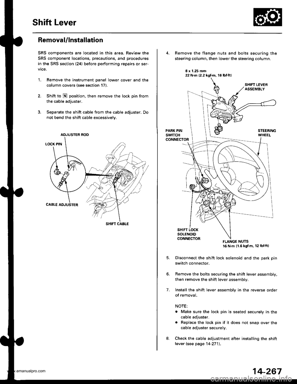
2. Shift to N position, then remove the lock pin from
the cable adjuster.
3. Separate the shift cable from the cable adjuster, Do
not bend the shift cable excessively.
ADJUSTER ROD
SHIFT CABLE
22 N.m (2.2 kgf.m, 16 lbt.ftl
7.
Remove the flange nuts and bolts securing the
steering column, then lower the steering column.
FLANGE NUTS16 N m (1.6 kgl m, 12 lbt'ftl
Disconnect the shift lock solenoid and the park pin
switch connector.
Remove the bolts securing the shift lever assembly,
then remove the shift lever assembly.
lnstall the shift lever assembly in the reverse order
of removal.
NOTE;
. Make sure the lock pin is seated securely in the
cable adjuster.
. Replace the lock pin if it does not snap over the
cable adjuster securely.
Check the cable adjustment after installing the shift
lever (see page 14-27'l).
14-267
www.emanualpro.com
Page 784 of 1395
Shift Lever
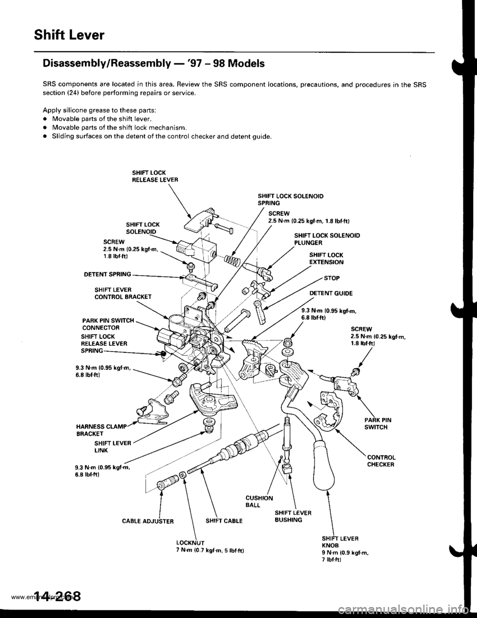
Disassembly/Reassembly -'97 - 98 Models
SRS components are located in this area. Review the SRS component locations. precautions. and procedures in the SRS
section (24) before performing repairs or service.
Apply silicone grease to these parts'
. Movable parts of the shift lever,
. Movable parts of the shift lock mechanism.
. Sliding surfaces on the detent of the control checker and detent guide.
SHIFT LOCK SOLENOIDSPRING
SCREW
SHIFT LOCK2.5 N.m {0.25 kgtm, 1.8 lbtftl
SCREW2.5 N.m {0.25 kg{.m,1.8 rbf.ft)
SHIFT LOCK SOLENOIDPLUNGER
SHIFT LOCKEXTENSION
DETENT SPFING
SHIFT LEVER
PARK PIN SWITCHCONNECTOR
SHIFT LOCKRELEASE LEVER
CONTROL BRACKET
STOP
DETENT GUIDE
9.3 N.m 10.95 kgtm,6.8 tbrft)
SPRING
9.3 N.m {0.95 kgf.m,6.8 tbf.ftl
SHIFT LEVERLINK
9.3 N.m (0.95 kgt.m,6.8 tbf.ftl
SHIFT CAALE
KNOBI N.m 10.9 kgt.m,7 rbf.ftl
14-268
7 N.m {0.7 kgf.m.5 tbt.fr}
www.emanualpro.com
Page 785 of 1395
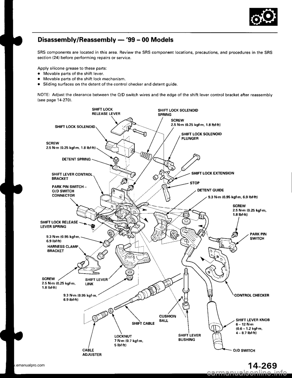
Disassembly/Reassembly -'99 - 00 Models
SRS components are located in this area. Review the SRS component locations, precautions, and procedures in the SRS
section (24) before performing repairs or service.
Apply silicone grease to these parts:
. Movable parts of the shift lever.
. Movable parts of the shift lock mechanism.
. Sliding surfaces on the detent of the control checker and detent guide.
NOTE: Adjustthe clearance between the O/D switch wires and the edge ofthe shift lever control bracket after reassembly(see page 14-270).
SHIFT LOCKRELEASE LEVERSHIFT LOCK SOLENOIDSPRING
SCREW2.5 N.m {0.25 kgf.m, 1.8lbtft)SHIFT LOCK SOLENOID
SCREW2.5 N.m (0.25 kgl.m, 1.8 lbl.ft)
SHIFT LOCK SOLENOIOPLUNGER
DETENT SPRING
SHIFT LEVER CONTROLBRACKET
PARK PIN SWITCH _
o/D swtTcHCONNECTOB
SHIFT LOCK EXTENSION
STOP
DETENT GUIDE
9.3 N.m {0.95 kgf.m, 6.9 lbl.ftl
SCREW2.5 N.m {0.25 kgt m,1.8 tbf.ftl
SHIFT LOCK BELEASELEVER SPRING
9.3 N.m {0.95 kgl.m,6.9 lbtfr)
HARNESS CLAMPERACKET
PARK PINswrTcH
SCREW2.5 N.m {0.25 kgf.m,1.8 tbl.f0
9.3 N.m 10.95 kgtm,6.9 tbf.ft)CONTROL CHECKER
SHIFT LEVER KNOB6- 12 N.m{0.6 - 1.2 kgt'm,4 - 8.7 tbnft)LOCKNUT7 N.m {0.7 kgl.m,5 tbf.ftl
SHIFT LEVERBUSHING
o/D swtTcH
14-269
www.emanualpro.com
Page 952 of 1395
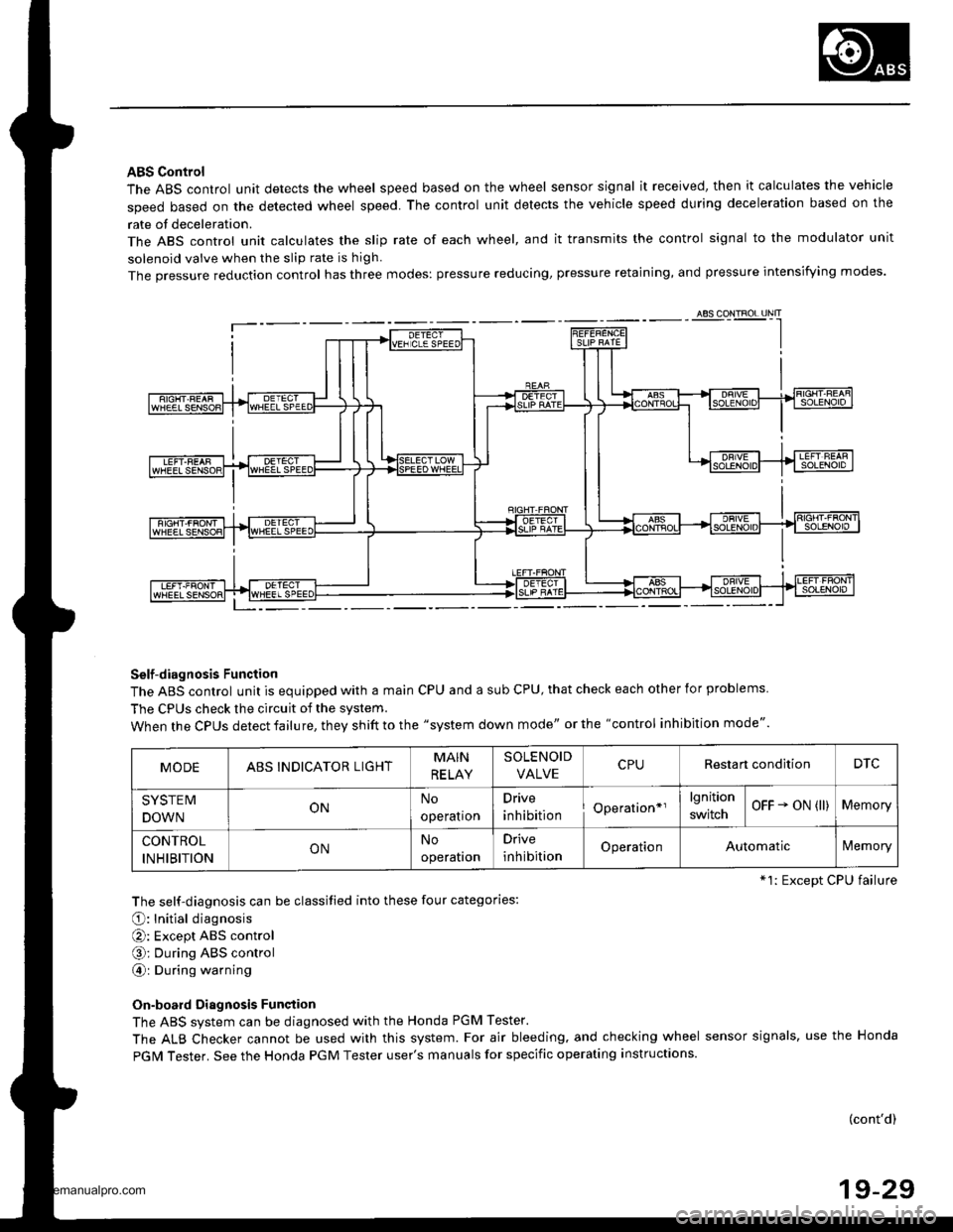
ABS Control
The ABS control unit detects the wheel speed based on the wheel sensor signal it received, then it calculates the vehicle
speed based on the detected wheel speed. The control unit detects the vehicle speed during deceleration based on the
rate of deceleration.
The ABS control unit calculates the slip rate of each wheel, and it transmits the control signal to the modulator unit
solenoid valve when the slip rate is high
The pressure reduction control has three modes: pressure reducing, pressure retaining, and pressure intensi{ying modes.
Self-diagnosis Function
The ABS control unit is equipped with a main cPU and a sub cPU, that check each other for problems.
The CPUs check the circuit of the system.
When the CPUS detect failure, they shift to the "system down mode" or the "control inhibition mode".
The self-diagnosis can be classitied into these four categories:
O: Initial diagnosis
O: Except ABS control
O; During ABS control
@: During warning
On-board Diagnosis Function
The ABS system can be diagnosed with the Honda PGM Tester.
The ALB Checker cannot be used with this system. For air bleeding. and checking wheel sensor signals, use the Honda
PGIM Tester. See the Honda PGM Tester user's manuals for specific operating instructions.
(cont'd)
19-29
ABS CONTROL I-INIT
MODEABSINDICATOR LIGHTMAIN
RE LAY
SOLENOID
VALVERestan conditionDTC
SYSTEM
DOWNONNo
operatron
Drive
inhibitionOperation*rlgnition
switchOFF - oN (ll)Memory
CONTROL
INHIBITIONONNo
operaton
Drive
inhibitionOperationAutomaticlVemory
*1: Except CPU failure
www.emanualpro.com
Page 1174 of 1395
![HONDA CR-V 1999 RD1-RD3 / 1.G Repair Manual
Connector ldentification and Wire Harness Routing
Engino Wire Harness
Connecto; or
Terminal
Number of
CavitiesLocationConneqts toNotos
c101
c102
c103
c 104
c105
c105
c106
c 107
c 108
c 109
c]10
c1ll HONDA CR-V 1999 RD1-RD3 / 1.G Repair Manual
Connector ldentification and Wire Harness Routing
Engino Wire Harness
Connecto; or
Terminal
Number of
CavitiesLocationConneqts toNotos
c101
c102
c103
c 104
c105
c105
c106
c 107
c 108
c 109
c]10
c1ll](/img/13/5778/w960_5778-1173.png)
Connector ldentification and Wire Harness Routing
Engino Wire Harness
Connecto; or
Terminal
Number of
CavitiesLocationConneqts toNotos
c101
c102
c103
c 104
c105
c105
c106
c 107
c 108
c 109
c]10
c1l'l
c112
c113
c't 14
cl16
cl16
c117
c118
c119
c120
c121
c't22
c't23
c't25
cl26
cl27
cr 28
cl29
c130
c131
c132
c 133
c134
c134
c135
c 136
10
6
1
2
1
2
1
10
20
31
16
22
l0
l0'14
14
1
Left side of engine compartment
Left side of engine compartment
Middle of engine
Middle of engine
Left side of engine compartment
Left side of engine compartment
Middle of engine
Middle of engine
Middle of engine
Middle of engine
Middle of engine
Middle of engine
Middle of engine
Middle of engine
Middle of engine
Middle of engine
Middle of engine
Middle of engine
Middle of engine
Middle of engine
Middle of engine
Right side of engine
Middle of engine
Behind right kick panel
Under right side of dash
Under right side of dash
Under right side of dash
Under right side of dash
Under right side of dash
Right side of engine
Right side of engine
Middle of engine
Middle of engine
Middle of engine
Middle of engine
Middle of engine
Middle of engine
Left side of engine compartment
Middle of engine
Middle of engine
Main wire harness (C304)
Main wire harness (C305):'97 - 98 models
No. 1 fuel injector
Crankshaft speed fluctuation (CKF) sensor
Alternator
Alternator
Engine oil pressure switch
No.2 fuel injector
Evaporative emission (EVAP) purge
control solenoid valve
No. 3 fuel injector
No. 4 fuel injector
Primary heated oxygen sensor(Primary HO2S) (sensor 1)
Radiator fan switch
Coolant temperature sending unit
Engine coolant temperature (ECT) sensor
Mainshaft speed sensor
Lock-up control solenoid valve
Back-up light switch
Shift control solenoid valve
Linear solenoid valve
Countershaft speed sesnsor
Starter solenoid
Distributor
Junction connector
PCM
ECIWPCM
ECM/PCM
ECM/PCM
Main wire harness (C,|:}1)
IVT gear position switch
Vehicle speed sensor (VSS)
Throttle position (TP) sensor
MAP sensor
ldle air control (lAC)valve
lntake air temperature (lAT) sensor
Junction connector
Junction connector
Power steering pressure (PSP) switch
Junction connector
Knock sensor (KS)
A/r
USA
Canada
Alr
AlT
M/'r
Afi
'97mooel
'97 model'98 - 00
mooets
'99 - 00
models
T101
r102
Left side of en0ine companment
Right side of engine compartment
Alternator
Under-hood fuse/relay box
G101Middle of engineEngine ground, via engine wire harness
23-14
www.emanualpro.com
Page 1196 of 1395
![HONDA CR-V 1999 RD1-RD3 / 1.G Repair Manual
Connector ldentification and Wire Harness Routing
Hoat6r Sub-harness
Connector or
Tgrminal
Numbsr ot
CavitiesLocalionConnects toNotes
c73�]
c731
c732
c733
c734
c735
c736
c737
c738
c739
c7 40
c7 40
5 HONDA CR-V 1999 RD1-RD3 / 1.G Repair Manual
Connector ldentification and Wire Harness Routing
Hoat6r Sub-harness
Connector or
Tgrminal
Numbsr ot
CavitiesLocalionConnects toNotes
c73�]
c731
c732
c733
c734
c735
c736
c737
c738
c739
c7 40
c7 40
5](/img/13/5778/w960_5778-1195.png)
Connector ldentification and Wire Harness Routing
Hoat6r Sub-harness
Connector or
Tgrminal
Numbsr ot
CavitiesLocalionConnects toNotes
c73'�]
c731
c732
c733
c734
c735
c736
c737
c738
c739
c7 40
c7 40
5
7
7
24
1
Under middle of dash
Under middle of dash
Behind middle of dash
Behind middle of dash
Behind glove box
Behind glove box
Behind glove box
Behind glove box
Behind glove box
Behind glove box
Behind middle of dash
Behind middle of dash
Main wire harness {C436)
Main wire harness (C436)
Mode control motor
Dashboard wire harness (C522)
Air mix control motor
Evaporator temperature sensor
Blower motor high relay
Blower motor
Power transistor
Recirculation control motor
Dashboard wire harness (C523)
Dashboard wire harness (C523)
'97 model'98 - 00
modsls
'97 model'98 - 00
mooels
Combination Switch Sub-harness
Conneqtor ol
Terminal
Number of
CavitiesLocationConnests toNotos
c751
c753
c754
c755
c756
c757
c758
c760
c760
6
7
12
10
2
7
6
8
5
Above under-dash fuse/relay box
Above under-dash fuse/relay box
Under left side of dash
Under left side of dash
Behind steering column
Behind steering column
Behind steering column
Behind steering column
Behind steering column
Behind steering column
Under left side of dash
Under left side of dash
Under-dash fuse/relay box (C914)
Under-dash fuse/relay box {C915)
Main wire harness (C413)
Main wire harness (C413)
Shift lock solenoid
Parking pin switch
Combination light switch
Combination light switch
Wiper/washer switch
Wiper/washer switch
Main wire harness (C442)
Main wire harness (C442)
'97 - 98
mod6ls'99 - 00
models
'97 - 98
models'99 - 00
models
23-36
,
www.emanualpro.com
Page 1205 of 1395
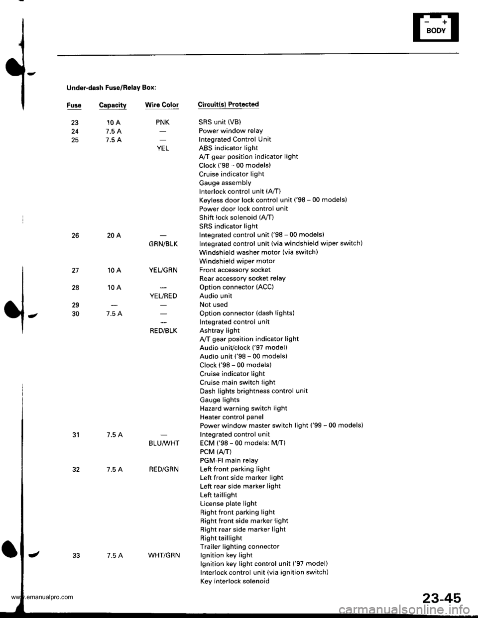
under-dash Fuse/Relay Box:
Fuse Capacitywir6 ColorCircuit(sl Protocted
SRS unit (VB)
Power window relay
Integrated Control Unit
ABS indicator light
A/T gear position indicator light
Clock ('98 - 00 models)
Cruise indicator light
Gauge assembly
Interlock control unit (A,/T)
Keyless door lock control unit ('98 - 00 models)
Power door lock control unit
Shift lock solenoid (lVT)
SRS indicator light
Integrated control unit ('98 - 00 models)
Integrated control unit (via windshield wiper switch)
Windshield washer motor (via switch)
Windshield wiper motor
Front accessory socket
Rear accessory socket relay
Option connector (ACC)
Audio unit
Not used
Option connector (dash lights)
Integrated control unit
Ashtray light
A,/T gear position indicator light
Audio univclock ('97 model)
Audio unit ('98 - 00 models)
Clock ('98 - 00 models)
Cruise indicator light
Cruise main switch light
Dash lights brightness control unit
Gauge lights
Hazard warning switch light
Heater control panel
Power window master switch light ('99 - 00 models)
Integrated control unit
ECM ('98 - 00 models: M/T)
PCM (4./T)
PGM-Fl main relay
Left front pa.king light
Left front side marker light
Left rear side marker light
Left taillight
License plate light
Right front parking light
Right front side marker light
Right rear side marker light
Right taillight
Trailer lighting connector
lgnition key light
lgnition key light control unit ('97 model)
Interlock control unit (via ignition switch)
Key interlock solenoid
25
PNK
;
10 A
7.5 A
7.5 A
28
10A
10A
7.5 A
204
7.5 A
7.5 A
GRN/BLK
YEUGRN
YEURED
a, olrL"
29
30
BLU,ryVHT
RED/GRN
7.5 AWHT/G R N
23-45
www.emanualpro.com