under dash fuse box HONDA CR-V 1999 RD1-RD3 / 1.G Manual PDF
[x] Cancel search | Manufacturer: HONDA, Model Year: 1999, Model line: CR-V, Model: HONDA CR-V 1999 RD1-RD3 / 1.GPages: 1395, PDF Size: 35.62 MB
Page 1278 of 1395
Wipers/Washers
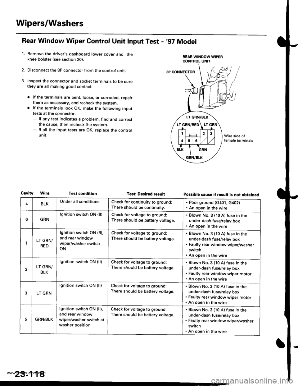
Rear Window Wiper Gontrol Unit lnput Test -'97 Model
Remove the driver's dashboard lower cover and theknee bolster {see section 20).
Disconnect the 8P connector from the control unit.
Inspect the connector and socket terminals to be surethey are all making good contact.
a lf the terminals are bent, loose, or corroded, repair
them as necessary. and recheck the system.. lf the terminals look OK, make the following input
tests at the connector.- lf any test indicates a problem, find and correct
the cause, then recheck the system.- lf all the input tests are OK, replace the control
UNII.
1.
LT GRN/BLK
T GRN/RED LT
12
16
GRN/BLK
8P CONNECTOF
CavityTest condhion Test Desir€d r93uhPossible cause il rasuh is not obtained
4BLKUnder all conditionsCheck for continuity to ground:
There should be continuity.
. Poor ground (G401, c402). An open in the wire
GRN
lgnition switch ON (lllCheck for voltage to ground;
There should be battery voltage.
Blown No. 3 (10 A) fuse in the
under-dash fuse/relay box
An open in the wire
'lLT GRN/
RED
lgnition switch ON ( ll),
and rear window
wiper/washer switch
ON
Check for voltage to ground:
There should be battery voltage.
Blown No. 3 (10 A) fuse in the
under-dash fuse/relay box
Faulty rear window wiper/washer
switch
An open in the wire
LT GRN/
BLK
lgnition switch ON (lllCheck for voltage to ground;
There should be battery voltage.
Blown No. 3 {10 A) fuse in the
under-dash fuse/relay box
Faulty rear window wiper motor
An open in the wire
LT GRN
lgnition switch ON (ll)Check for voltage to ground:
There should be battery voltage.
Blown No.3 {10 A)fuse in the
under-dash fuse/relay box
Faulty rgar window wiper motorAn open in the wire
5GRN/BLK
lgnition switch ON lll),
and rear window
wiper/washer switch at
washer position
Check for voltage to ground:
There should be battery voltage.
Blown No.3 (10 A) fuse in the
under-dash fuse/relay box
Faulty rear window wiper/washer
switch
An open in the wire
23-118
www.emanualpro.com
Page 1281 of 1395
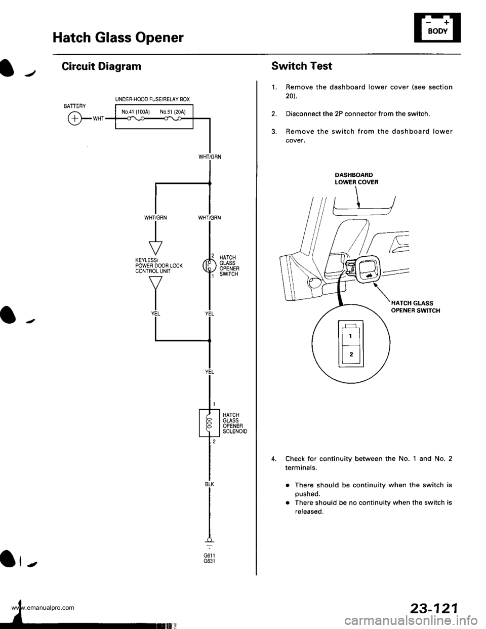
Hatch Glass Opener
Circuit Diagram
BATTEFY
@*"
UNDER.H@D FUSE/RELAY BOX
|-*;rr^!...',r,*;l.......1<\o<
+l
I
I
IWHT/GRN
WHT/GRN
II
rt
KEYLESSiPOWEF DOOB LOCKCONTROL UNIT
V
IIIYEL
HATCHGLASSOPENERsoLENOr0
J
TBLK
I
out,G631
WHT/GBN
Ot-
23-121
1. Remove the dashboard lower cover (see section
20).
2. Disconnect the 2P connector from the switch.
3. Remove the switch from the dashboard lower
cover.
Switch Test
DASHBOANDLOWER COVER
HATCH GLASSOPENER SWITCH
Check for continuity between the No. 1 and No. 2
terminals.
. There should be continuity when the switch is
pushed.
. There should be no continuity when the switch is
released.
www.emanualpro.com
Page 1284 of 1395
![HONDA CR-V 1999 RD1-RD3 / 1.G Manual PDF
Power Door Locks
UNDER.HOOD FUSE/FELAY BOX
Circuit Diagram (With Keyless Entry System)
GN TION SW TCHUNDER DASHFUSE/RELAY BOXEATTEFY
@*n
WHT/GFN
8
ITEYLES--lI TRANSMIT]ER ILr--------
. PASSENGENS DO HONDA CR-V 1999 RD1-RD3 / 1.G Manual PDF
Power Door Locks
UNDER.HOOD FUSE/FELAY BOX
Circuit Diagram (With Keyless Entry System)
GN TION SW TCHUNDER DASHFUSE/RELAY BOXEATTEFY
@*n
WHT/GFN
8
ITEYLES--lI TRANSMIT]ER ILr--------
. PASSENGENS DO](/img/13/5778/w960_5778-1283.png)
Power Door Locks
UNDER.HOOD FUSE/FELAY BOX
Circuit Diagram (With Keyless Entry System)
GN TION SW TCHUNDER DASHFUSE/RELAY BOXEATTEFY
@*n'
WHT/GFN
8
ITEYLES--lI TRANSMIT]ER ILr--------
. PASSENGENS DOOR SWITCHES. ]NTEGRATED CONTROL UNIT5
23-124
HORNRELAY
f7
II- GRY
FRONTCEILINGL GHT
Y_o*,,.,,,0-
HATCHGLASSOPENERSOLENO D
HATCH
OPENERswlTcH
f7
I
YEL
L
fIllBl
+BL(
I
G61lG63l
INTEGRATED ICoNTROL UN T I
,Y, I
F",'*-{
.,ufrro I
tl
rthg#,i."J L
T
8!?i"'[:lll',fffi)
BLK
I
I--
G401G402
YEL
8LK
I
G551
DRIVER'SDOOF LOCKswrTcH
UNLOCK
nrrenu @
LOCK
@
KEYLESSDOOs LOCKCONTROL UNIT
BLK
I
G551
--1
www.emanualpro.com
Page 1285 of 1395
UNDER-DASHFUSE/RELAYBOX
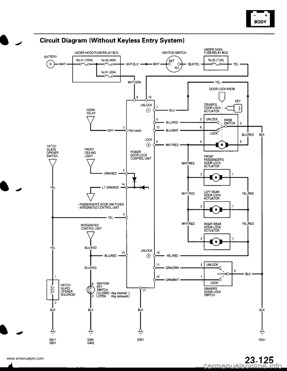
Circuit Diagram {Without Keyless Entry System)
IGNTION SWITCHBATTEBY
@**'
FRONTCEILINGTIGHT
V
l_
r-
HATCHGLASSOPENERSWTCH
f7
I
l-J';
tr| oBtvERsI DOOn LOCKACTUATOR
s l-lLocx^l-Tq. l,, | -=tGJ--
+ II Locx IDRIVER'SD00R LOC(SWITCN
KNOB
6 tr.*;lwrr 3-K +wqr-t_t- BLKYEL
ffr
vEL
YEURED
GRNORN
GRNWHT
HORNRELAY
V
BLK
II
I:
G551
23-125
INTEGRATEDCONTROL UNIT
V
IBLU/RED
I
l- 8Lr
IBLU/RED
II
Iupl ,#. L?Vno'::iii^ ( li: ) swrTcHYAil''"',4,.'{yrcLosED
l' tottt
IBLK
II
I':
G()1G402
YEL
t/ |
tFl
?BLK
I
G6l1
UNDER.HOOD FUSEi RELAY 8OX
(Nol used)
LOCK
o
POWERDOOR LOCKCONTROL UNIT
EIGHT REAR00oR LocKACTUATOR
'tl
www.emanualpro.com
Page 1287 of 1395
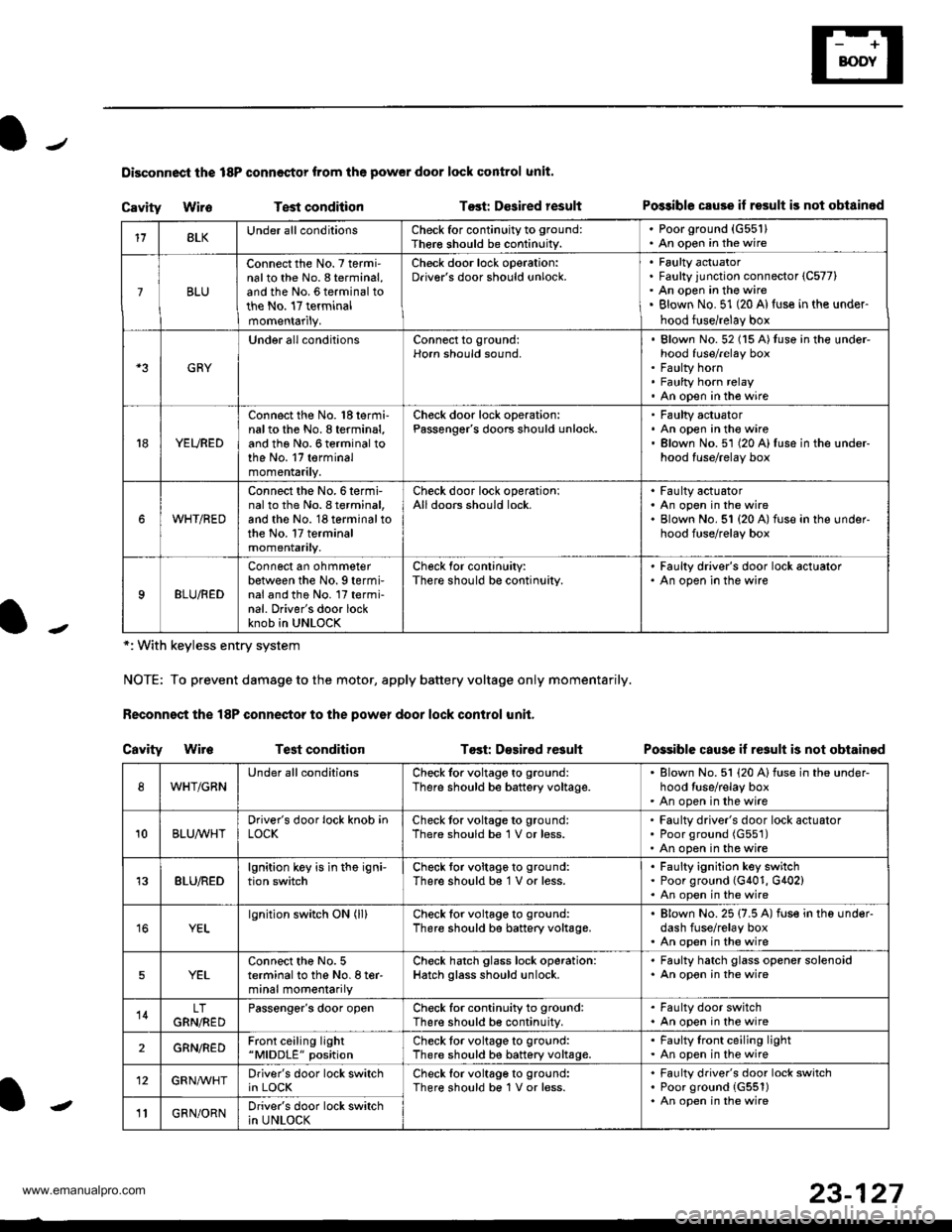
Disconnoci the 18P connestor from the pow€r door lock control unit.
Cavity WireTest conditionTost: Dcsired resultPo$ible csuse il result is not obtainod
Possible cause if result is not obtain€d
*: With keyless entry system
NOTE: To prevent damage to the motor, apply battery voltage only momentarily.
Feconnoct the 18P conneqtor to the power door lock control unit,
Cavity Wir6Test conditionTost: D€sirod result
118LKUnder all conditionsCheck for continuity to ground:
Ther€ should be continuity.
. Poorground (G55'l). An open in the wire
7BLU
Connect the No. 7 termi'nalto the No. 8 terminal,and the No. 6 terminal tothe No. 17 terminalmomentarily.
Check door lock operation:Driver's door should unlock.Faulty actuatorFaulty junction connector (C577)
An open in the wireBlown No. 51 (20 Al{use in the under-
hood fuse/relay box
GRY
Under all conditionsConnect to ground:Horn should sound,Blown No. 52 (15 A)tuso in the under-hood fuse/relay boxFaulty hornFaulty horn relayAn open in tho wire
YEURED
Connect the No. 'l8 termi-nalto the No. 8 terminal,and the No. 6 terminal tothe No. 17 terminalmomentarily.
Check door lock operation:Passenger's doors should unlock.Faulty actuatorAn open in the wireBlown No.51 (20 A)fuse in the under-hood fuse/relay box
WHT/RED
Connect the No.6termi-nal to th6 No. I terminal,and the No. 18 terminal tothe No. 17 terminalmomentarily.
Check door lock operationlAll doors should lock.Faulty actuatorAn open in the wireBlown No. 51 {20 A) fuse in ihe under-hood fuse/relay box
9BLU/RED
Connect an ohmmeterbetween the No. 9 termi-nal and the No. l7 termi-nal. Driver's door lockknob in UNLOCK
Check for conlinuity:There should be continuity.
' Faulty driver's door lock actualor. An open in the wire
WHT/GRNUnder all conditionsCheck for voltage to ground:
There should be battery voltage.Blown No. 51 (20 Alfuse in the under-hood tuse/relay boxAn open in the wire
10BLUAVHTDriver's door lock knob inLOCKCheck tor voltage to ground:There should be 1 V or less.Faulty driver's door lock actuatorPoor ground (G551)
An open in the wire
13BLU/REDlgnition key is in the igni-tion switchCheck tor voltage to ground:
There should b€ 1 V or less.Faulty ignition key switchPoor ground (G401, G402)An open in the wire
YELlgnition switch ON (ll)Check for voltage to ground:
There should be battery voltage.Blown No. 25 (7.5 A) fuse in the under-dash fuse/relay boxAn open in the wire
5YELConnect the No. 5terminal to the No. I ter-minal momentarily
Check hatch glass lock operation:Hatch glass should unlock.
. Faulty hatch glass opener solenoid. An opon in the wire
14LTGRN,NEDPassengor's door openCheck for continuity to ground:There should b€ continuity.
. Fa(llty door switch. An open in the wire
2GRN/R€DFront ceiling light"MlDDLE" positionCheck tor voltage to ground:There should be battery voltage.Faulty lront ceiling lightAn open in the wire
12GRNAr'VHTDriver's door lock switchin LOCKCheck lor voltage to ground:There should be 1V or less.Faulty driver's door lock switchPoor ground {G551)An open in the wire' GRN/ORNDriver's door lock switchin UNLOCK-
23-127
www.emanualpro.com
Page 1295 of 1395
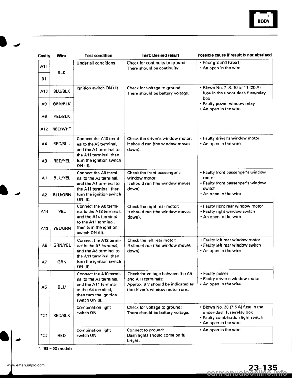
-
CavityWi1€Test conditionTesi: Dssired rosultPo$ible cause if 183uh is not obtained
A11
BLK
Under all conditionsCheck for continuity to ground:
There should be continuity.
. Poor ground (G551)
. An open in the wire
B1
A10BLU/BLKlgnition switch ON (ll)Check for voltage to ground:
There should be battery voltage.
Blown No. 7, 8, 10 or l1 (20 A)
fuse in the under-dash fuse/relay
box
Faulty power window relay
An open in the wire
A9GRN/BLK
A6YEUBLK
412RED/WHT
A4RE D/BLU
Connect the A10 termi-
nal to the 43 terminal,
and the A4 terminal to
the A11 terminal, then
turn the ignition switch
oN flr).
Check the driver's window motor:
It should run (the window moves
down).
. Faulty driver's window motor
. An open in the wire
A3RED/YEL
A1BLUI/EL
Connect the A9 termi-
nal to the A2 terminal,
and the Al terminal to
the 411 terminal, then
turn the ignition switch
oN flr).
Check the front Passenger'swindow motor:
It should run (the window moves
down).
Faulty front passenger's window
motor
Faulty front passenger's window
switch
An open in the wireA2BLU/ORN
A14YEL
Connect the 46 termi-
nalto the A13 terminal,
and the 414 terminal
to the A11 terminal,
then turn the ignition
switch ON (ll).
Check the right rear motor:
It should run (the window moves
oown).
Faulty right rear window motor
Faulty right window switch
An open in the wire
YEUGRN
A8GBN/YEL
Connect the A12 termi-
nal to the A7 terminat,
and the A8 terminal to
the A11 terminal. then
turn the ignition switch
oN flr).
Check the left rear motor:
,t should run {the window moves
down),
Faulty left rear window motor
Faulty ,eft rear window srrvitch
An open in the wire
GRN
A5BLU
Connect the A10 te.mi-
nal to the 43 terminal,
and the A11 terminal
to the 44 terminal.
then turn the ignition
switch ON (ll).
Check for voltage between the A5
and Al l terminals:
ADorox.6 V should be indicated as
the driver's window motor runs.
Faulty pulser
Faulty driver's window motor
An open in the wire
*clRED/BLK
Combination light
switch ON
Check fo. voltage to ground:
There should be battery voltage.
Blown No.30 (7.5 A) fuse in the
under-dash fuse/relay box
Faulty combination light switch
An open in the wire
RED
Combination light
switch ON
Connect to ground:
Dash lights should come on full
bright.
' An open in the wire
www.emanualpro.com
Page 1313 of 1395
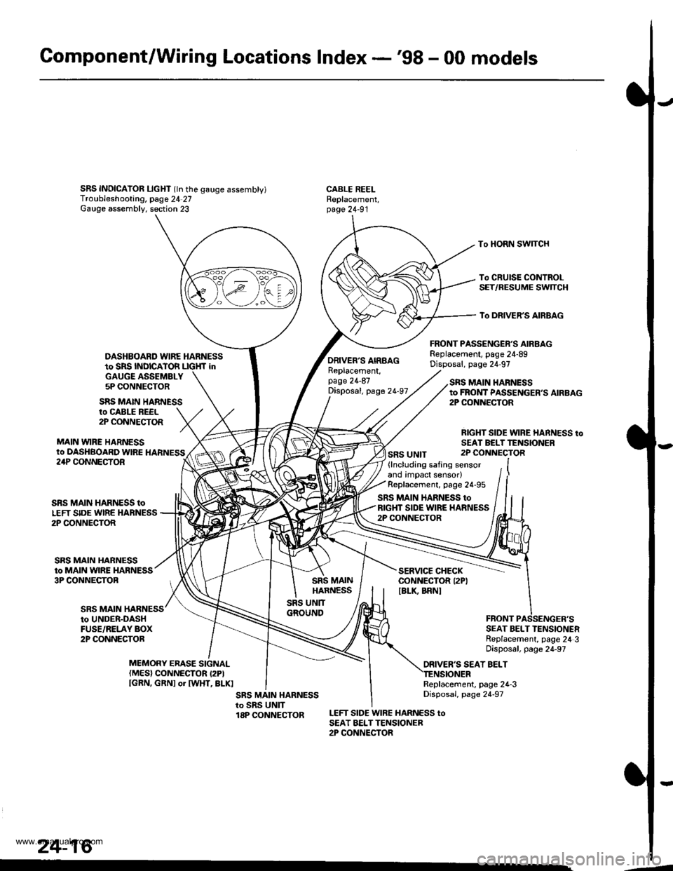
Gomponent/Wiring Locations Index -'98 - 00 models
SRS INDICAIOR LIcHT (ln the gauge assembty)Troubleshooting, page 24 27Gauge assembly. section 23
DASHBOARD WIRE HARNESSto SRS INDICATOR LIGHf inGAUGE ASSEMBLY5P CONNECTOR
FRONT PASSENGER'S AIRBAGReplacement, page 24-89Disposal, page 24 97
CABLE REELReplacement,page 24-91
To HORN SWITCH
To CRUISE CONTROLSET/RESUME SWTCH
To DRIVER'S AIRBAG
ro CABLE REEL2P CONNECTOR
MAIN VYIRE HARNESSto DASHBOARD WIRE HARNESS
SRS MAIN HARNESS
ORIVER'S AIRBAGReplacement,page 24-87Disposal, page 24-97
SRS UNIT
SRS MAIN HARNESSto FROI{T PASSENGER,S AIRBAG2P CONiIECTOR
RIGHT SIDE WIRE HARNESS toSEAI BELTTENSIONER2P CONNECTOR24P CONNECTOR
SRS MAIN
SRS MAIN HARNESS toLEFT SIDE WIRE HARNESS2P CONNECTOR
SRS MAIN HARNESSto MAIN WIRE HARNESS3P CONNECTOB
(lncluding safing sensorand impact sensor)Replacement, page 24-95
SRS MAIN HARNESS toRIGHT SIDE WIRE HARNESS2P CONNECTOR
SERVICE CHECKCONNECTOR I2PIIBLK BRNI
to UNDER-DASHFUSE/RELAY BOX2P CONNECTORSEAT BELT TENSIONERReplacement, page 24 3Disposal, page 24-97
ORIVER'S SEAT BELTMEMORY ERASE SIGNAL(MES) CONNECTOR I2PIIGRN, GRNI or IWHT, BLKIReplacement, page 24-3Disposal, page 24-97
LEFT SIDE WIRE HARNESS toSEAT BELTTENSIONER2P CONNECTOR
24-16
.4
www.emanualpro.com
Page 1315 of 1395
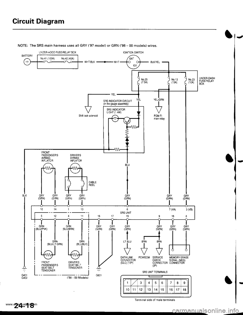
Circuit Diagram
UNDER.DASHFUSE/RELAYBOX
NOTE: The SRS main harness uses all GRY('97 model) or GRN ('98 - 00 models) wires.
WHT/BLK -'- WHT
DRIVEB'SAIRBAGNFLATOR
A
#+
tt tll./ d I
GRY GRY(GRN) (GRN)
FRONTPASSENGER'SALRBAGINFLAlOR
tlGRY GFY(GFN) (GRN)
DRIVER'SSEAT EELTTENSIONER
FRONTPASSENGERSSEAT BELTTENSIONEF
GRN(BLU/PNK)
BLK
G401
24-18
PCM/ECM SERVICE MEMORY ERASECHECK S GNAL (MES)CONNECTOB CONNECTOR(2P)
DATA LINXCONNECTOR(Drc) (r6P)
Models)('98 - 00
IGNITION SWITCHUNDEF,HOOD FUSE/RELAY BOX
YEUGRN
+
PGM FImam relay
SFS INDICATOR CIRCUIT(ln lhe gauge assembly)
Shill loc* so enoid
BLU
GR\
GNY GRY
H
GFY GRYlcFNt (GlN)
??
I r-?LT BLU BRN BRN
tttr?F?F
VVV
SRS NDICATORL GHT {r.4W)
5 12 4 11 | 16 17 15 I 18 I
10 14 113
U
S8S UN T TERMINALS
3567I
101114151718
Terminal side of male terminals
-4
www.emanualpro.com
Page 1322 of 1395
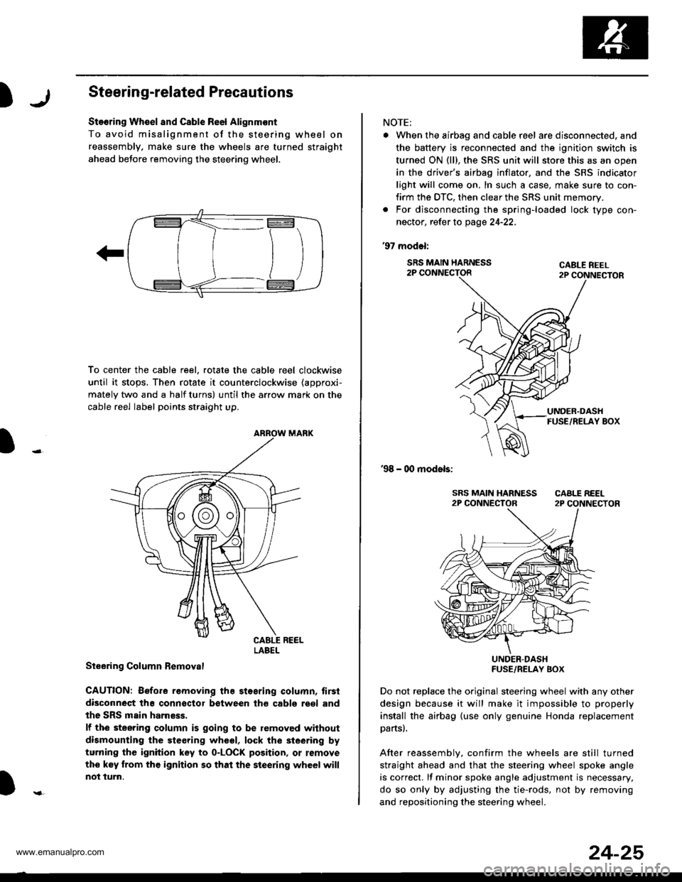
)Steering-related Precautions
Stooring Wh€el and Csble Re6l Alignm€nt
To avoid misalignment of the steering wheel on
reassembly, make sure the wheels are turned straight
ahead beJore removing the steering wheel.
To center the cable reel, rotate the cable reel clockwise
until it stops, Then rotate it counterclockwise (approxi-
mately two and a half turns) until the arrow mark on the
cable reel label points straight up.
Steering Column Bemoval
CAUTION: Before removing the stosring column, tirsi
disconneqt tha connsctor between tho cabls roel and
the SRS main harness.
lf the steering column is going to be removed without
dismounting the steering wheel, lock the sieering by
turning the ignition key to o-LOCK position, or remove
the key trom the ignition so that the steering wheel will
not turn.
LABEL
NOTE:
. When the airbag and cable r6el are disconnected, and
the battery is reconnected and the ignition switch is
turned ON (ll), the SRS unit will store this as an open
in the driver's airbag inflator, and the SRS indicator
light will come on, In such a case, make sure to con-
firm the DTC, then clear the SRS unit memory.
. For disconnecting the spring-loaded lock type con-
nector, refer to page 24-22.
'97 model:
SRS MAIN HARNESS2P CONNECTORCABLE REEL2P CONNECTOR
'98 - 00 models:
UNDER-DASHFUSE/RELAY BOX
Do not replace the original steering wheel with any other
design because it will make it impossible to properly
install the airbag (use only genuine Honda replacement
partsl.
After reassemblv, confirm the wheels are still turned
straight ahead and that the steering wheel spoke angle
is correct. lf minor spoke angle adjustment is necessary,
do so only by adjusting the tie-rods, not by removing
and repositioning the steering whee .
24-25
www.emanualpro.com
Page 1330 of 1395
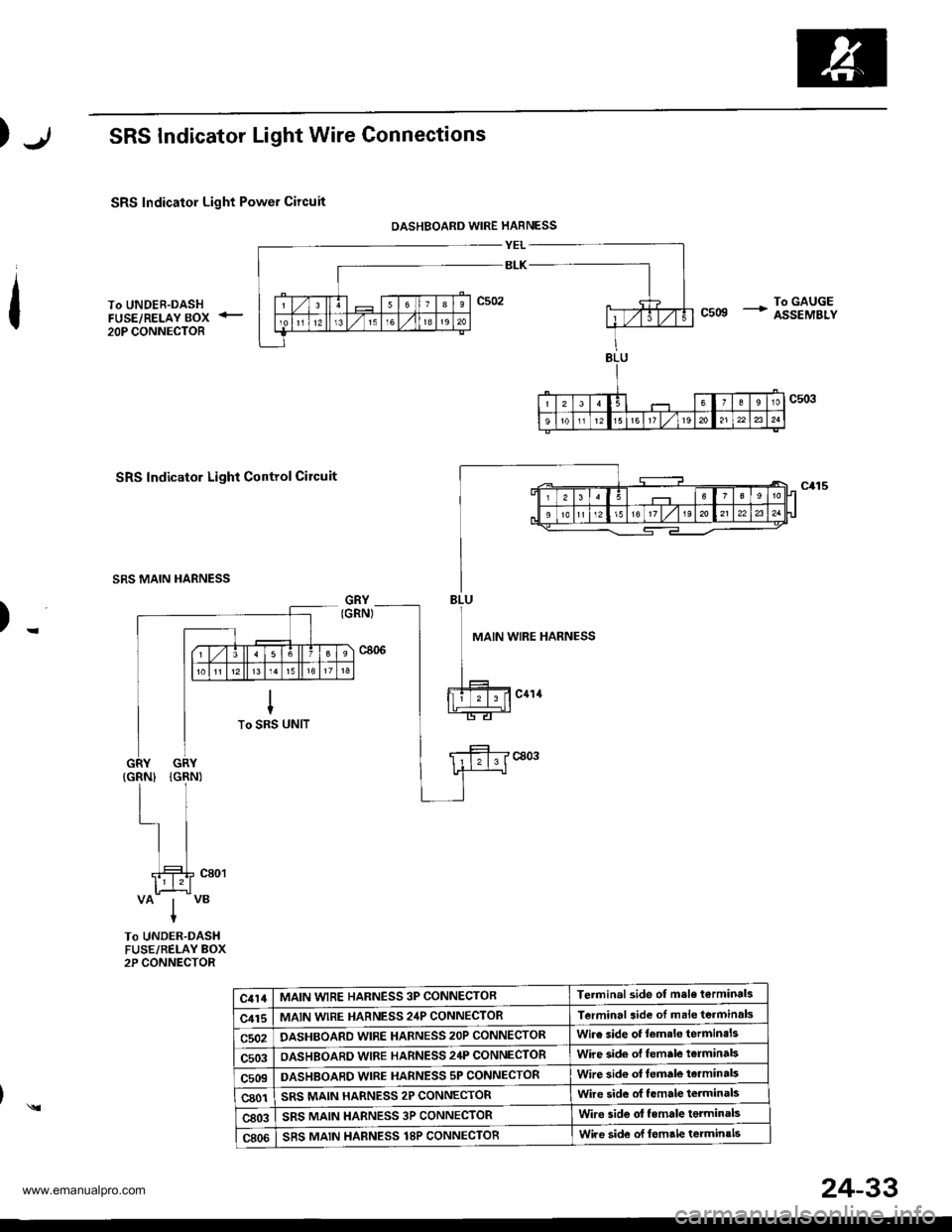
SRS Indicator Light Wire Connections
SRS Indicator Light Power Circuit
DASHBOARD WIRE HARNESS
YEL
BLK
To UNDER-DASHFUSE/RELAY BOX <_
20P CONNECTOR
To GAUGEcsog + assEMBLy
SRS Indicator Light Control Circuit
SRS MAIN HARNESS
)-MAIN WIRE HARNESS
VAIVBIt
To UNDER-DASHFUSE/BELAY BOX2P CONNECTOR
c414MAIN WIRE HARNESS 3P CONNECTORTerminal side of msle t€rminals
c415MAIN wlRE HARNESS 24P CONNECTORTerminal aide of male terminals
c502DASHBOARD WIRE HARNESS 2OP CONNECTORWire side of lemslo terminsls
c503OASHBOARD WIRE HARNESS 24P CONNECTORWire side of female t€rminal3
c509DASHBOABD WIRE HARNESS 5P CONNECTORWire sid€ ot lemale te.minals
c801SRS MAIN HARNESS 2P CONNECTORwire side ol f.male terminals
c803SRS MAIN HARNESS 3P CONNECTORWire side ol female terminals
c806SRS MAIN HARNESS T8P CONNECTORWire side of lomrle terminals
)
24-33
www.emanualpro.com