11 of 124 HONDA CR-V 1999 RD1-RD3 / 1.G Workshop Manual
[x] Cancel search | Manufacturer: HONDA, Model Year: 1999, Model line: CR-V, Model: HONDA CR-V 1999 RD1-RD3 / 1.GPages: 1395, PDF Size: 35.62 MB
Page 32 of 1395
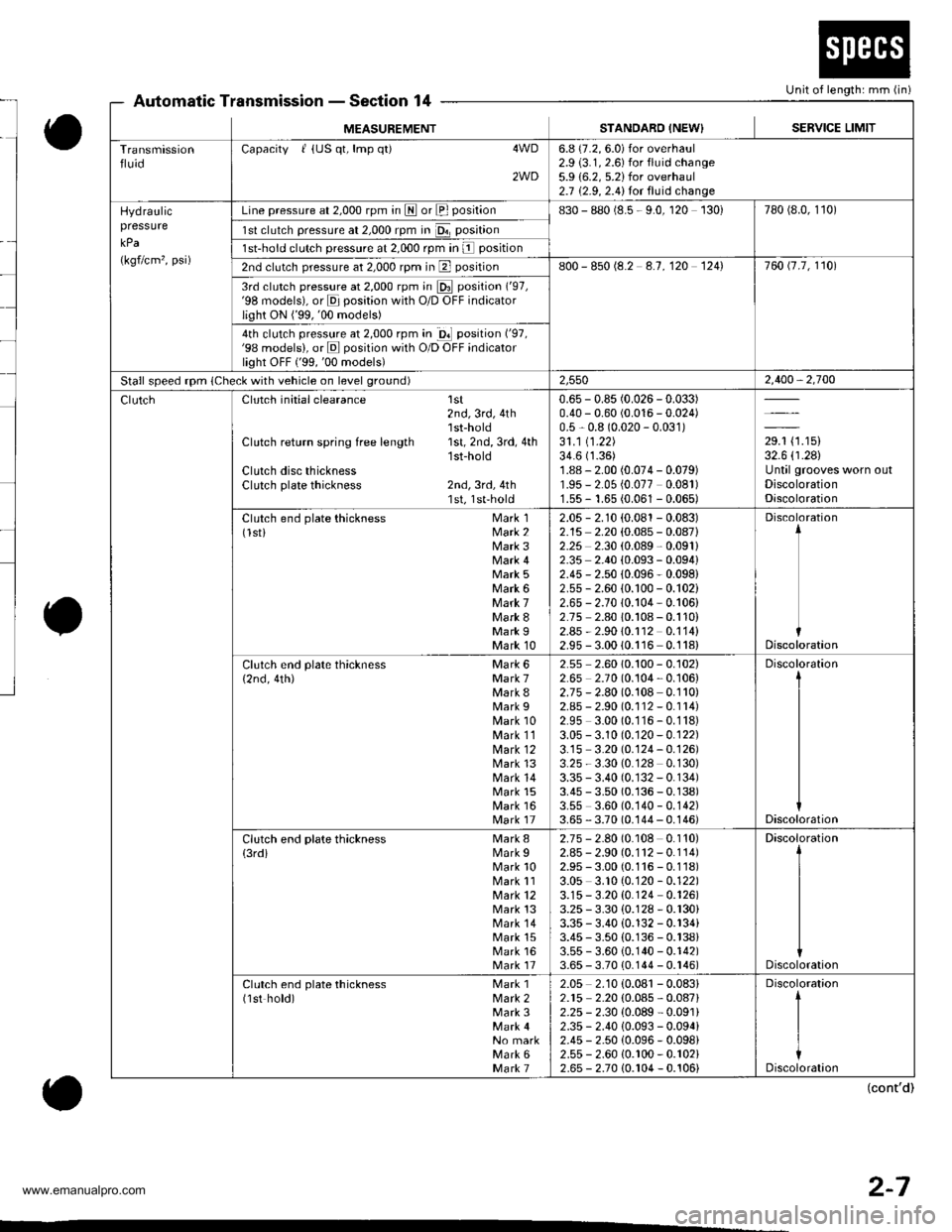
Unit of length: mm (in)Automatic TransmissionSection 14
MEASUREMENTSTANDARO INEW}SERVICE LIMIT
TransmissionfluidCapacity I {US qt, lmp q0 4WD
2WD
6.8 (7.2, 6.0) for overhaul2.9 (3.1, 2.6) for fluid change5.9 {6.2, 5.2)for overhaul2.7 {2.9, 2.4}for fluid change
Hydraulicpressure
kPa
(kgflcm'�, psi)
Line pressure at 2,000 rpm in LII or El position830 - 880 (8.5 - 9.0, 120 130)780 (8.0, 1'�t0)
1sl clutch pressure at 2,000 rpm in Da position
1st-hold clutch pressure at 2,000 rpm In l position
2nd clutch pressure at 2,000 rpm in El position800 - 850 (8.2 4.7,120 1241760 t7.7, 1101
3rd clutch pressure at 2,000 rpm in E position ('97,'98 models), or E position with O/D OFF indicatorlight ON ('99,'00 models)
4th clutch pressure at 2,000 rpm in gl position ('97,'98 models), or E position with O/D OFF indicatorlight oFF ('99,'00 models)
Stall speed rpm (Check with vehicle on level ground)2,5502,400,2,700
Clutch initial clearance 1st2nd,3rd,4th'lst-hold
Clutch return spring free length 1st, 2nd, 3rd, 4th'1st-hold
Clutch disc thicknessClutch plate thickness 2nd, 3rd, 4th1st, 1st-hold
0.65 - 0.85 (0.026 -0.033)
0.40 - 0.60 (0.016 - 0.024)0.5 - 0.8 (0.020 - 0.031)31 .1 11 .22)34.6 (1.36)
1.88 - 2.00 (0.074 - 0.079)'r.95 - 2.05 {0.077 0.081)'1.55- 1.65 (0.061 - 0.065)
29.1 (1.15)
32.6 (r.28)
Until grooves worn outDiscolorationDiscoloration
Clutch end plate thickness Mark 1(lsti Mark 2Mark 3Mark 4Mark 5Mark 6Mark 7Mark 8Mark IMark 10
2.05 - 2.r0 (0.081 - 0.083)2.15 2.20 (0.085 - 0.08712.25 2.30 (0.089,0.091)
2.35 2.40 {0.093 - 0.094}2.45 - 2.50 {0.096- 0.098}2.55 - 2.60 (0.100 - 0.102)2.65 - 2.70 (0.104 - 0.106)2.75 2.80 i0.108 - 0.110)2.85 - 2.9010.r 12 0.114)2.95 - 3.0010.116 0.118)
Discoloration
Discoloration
Clutch end plate thickness Mark 6{2nd, 4th) Mark 7Mark 8Mark 9Mark 10Mark 11lvlark 12Mark 13Mark 14Mark 15Mark 16Mark 17
2.55 2.60 10.100 - 0.102)2.65 2.70(0.104,0.106)2.75 - 2.80 (0.108 0.110)2.85 - 2.90 (0.112 -0.rr4)
2.95 3.00 (0.116-0.118)
3.05 - 3.10 (0.120 - 0.122)3.15 3.20 (0.124-0.126)
3.25 - 3.30 (0.128 0.130)3.35 - 3.40 (0. r32 - 0.134)3.45 - 3.50 (0.136 - 0.138)3.55 3.60 (0.140 - 0.142)3.65 - 3.70 (0.144 - 0.146)
Discoloration
Discoloration
Clutch end plate thickness Mark 8
{3rdi Mark IMark 10Mark 11Mark 12Mark 13Mark 14Mark 15Mark 16Mark 17
2.75 - 2.80 (0.108 0.110)2.85- 2.90 (0.112 - 0.114)2.95 - 3.00 (0.116 - 0.1'�j8)3.05 3.10 (0.120 - 0.122)3.15-3.20 {0.124 0.126)3.25 - 3.30 (0.128 - 0.r30)3.35 - 3.40 (0.132 - 0.r34i3.45 - 3.50 (0.136 - 0.138)3.55 - 3.60 {0.140 - 0.142)3.65 - 3.70 {0.144 - 0.r46)
Discoloration
Discoloration
Clutch end plate thickness Mark 1(1st hold) Mark 2Mark 3
No markMark 6Mark 7
2.05 2.10 (0.081 - 0.08312.r5 2.20 (0.085 - 0.087)2.25 - 2.30 {0.089 - 0.091}2.35 - 2.40 10.093 - 0.094i2.45 - 2.50 (0.096- 0.098i2.55 - 2.60 (0.r00 - 0.102)2.65 - 2.70 (0.r04 - 0.106)
(cont'd)
2-7
www.emanualpro.com
Page 204 of 1395

Fuel and Emissions
Special Tools ...................... 11-2
Component Locations
lndex ...................... ....,.... 11-3
Svstem Description
Vacuum Connections ...........,....,.,................. 1 1-9
Electrical Connections ................................... 1 1-15
System Connectors .,.,,.,............................,.,. 1 1-36
Troubleshooting
Troubleshooting Procedures,.,..................... 11-60
Engine Control Module/Powertrain ConttolModule Terminal Arrangement .............., 11-67
Diagnostic Trouble Code Chart .................... 1 t-75
How to Read Flowcharts .......,.....,.,............... I 1-79
PGM-Fl System
System Description .................,.,.,,,............... 1 1-80
Troubleshooting Flowcharts
Engine Control Module/PowertrainControl Module ........11-52
Manifold Absolute Pressure Sensor ............. 11-90
Intake Air Temperature Sensor .................... 1 1-95
Engine Coolant Temperature Sensor .,..,.,.... 1 1-99
Throttle Position Sensor ...........,.....,.,.,..,...... I 1'103
Primary Heated Orygen Sensor (Sensor 1) ... 11-110
Secondary Heated Oxygen Sensor{Sensor 2l .................. 1 1-117
Heated Oxygen Sensor Heater ..................... 11-121
Fuef Supply System ......11-124
Random Misfire ,....,.,..... 11-126
Mistire Detected in One Cylinder .....-........... 11-128
Knock Sensor ................ 11-130
CKP/TDC/CYP Sensor .................................... 1 1-131
Vehicle Speed Sensor ...............................,.... 1 1-135
Barometric Pressure Sensor .....,...,...,.,,........ 1 1-137
Electrical Load Detector ...,.,.......................... 1 1-138
CKF Sensor ................,.,, '11-112
ECM/PCM lnternaf Circuit ............................. 11'117
HO2S Replacement .,.,.,. 11-148
ldle Control System
System Description ............ 11-149
Troubleshooting Flowcharts
ldle Control System ...... 11-150
fdle Air Control Valve ......................,............. 11-152
Air Conditioning Signal ................................. I 1-155
Alternator FR Signal ...................................... 1 1-159
Starter Switch Si9na1 .................................... t l-161
Power Steering Pressure Switch Signal ...... 11-162
Brake Switch Si9na1 ...................................... 11-166
Fast ldle Thermo Valve .,.,.............................,.,.,. 11-168
ldle speed setting .............. 11-169
Fuel Supply System
Fuel Lines ............................ 11-171
Fuef Tube/Ouick-Conneci Fittings ..................... 11 -175
System Description ............ 11-178
Fuel Pressurg ...................... 11-178
Fuel Iniectors ................,..... 11-179
Fuel Pressure Re9u1ator .............................,.,...., f 1-181
Fuef Fifter ....,.,.,.,,,,.,............11-142
Fuel Pump ........................... 11-183
Fuel Gauge .......................... 11-184
Fuel Gauge Sending Unit ................................... I 1-185
Low Fuel Indicator System ...........,.,..,............... 1 1-185
PGM-FI Main Relay ............. 11-187
Fue|Tank................ ............. 11-191
Intake Air System
System Description ............ 11-193
Air Cleanel ,.,.,..................... 11-194
Throttle Cable ..................... 11-194
Throttle Body........ .............. 11-196
Emission Control System
System D$cription ...,....,.,. 11-199
Tailpipe Emission ............... 11-199
Three Way Catalytic Converter ..................,.,...,, 11-199
Positive Crankcase Ventilation System .,.,,,,.,.., 11-2O1
Evaporative Emission Controls .........,.,.,............ 11-203
www.emanualpro.com
Page 247 of 1395
1 2\3 156
16
18iJq11 12 13 ra15'11l8
cr25 tPCM-Cl
ct23 {PCM-Alc124 (PCM,B)
cr26 tPicM-ol
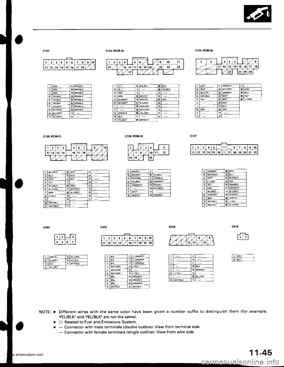
Different wires with the same color have been given a number suffix to distinguish them (for exampie,
YEUBLKT and YEUBLK2 are not the same).
O: Related to Fuel and Emissions Svstem.- Connector with male terminals (double outline): View from terminal side
- Connector with female terminals (single outline): View from wire side
NOTE: o
oo
,,
.t
o
an
123a5X67A910
rr l1213lat5t611t819 20
!to
lit
Doo
nn
ii)
o
a
12568910
11 112t3!il'16It't8t9 20
11-45
www.emanualpro.com
Page 261 of 1395
t23a1I12t3lta't5t011t8t9
c't22
c126 (PCM-O)*,
ot33
c124 {ECM/PCM.B}
C,r47 (ECM/PCM-Al
c121*3c127'�.
cl25 tECM/PCM-C)
c132
o
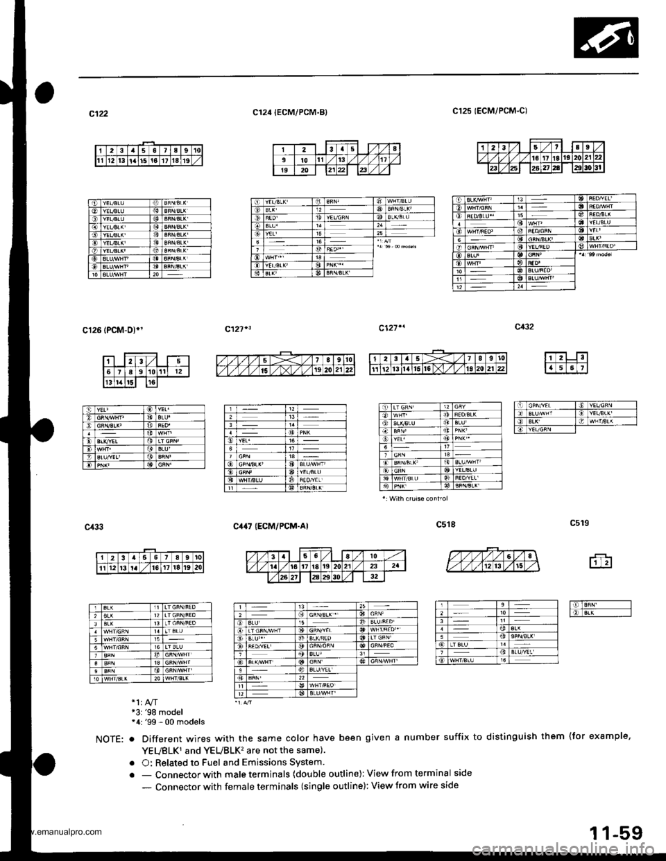
*1:4,/T '1 all*3: '98 model'4:'99 - 00 models
NOTE: . Different wires with the same color have been given a number suffix to distinguish them {for example,
YEUBLK1 and YEUBLK'�are not the same).
. O: Related to Fuel and Emissions Svstem.
. - Connector with male terminals (double outline): View from terminal side
- Connector with female terminals (single outline): View from wire side
tt
36,10
1t12l3l617lat9
11-59
www.emanualpro.com
Page 278 of 1395
Troubleshooting
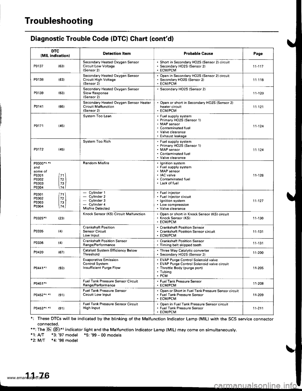
Diagnostic Trouble Code (DTCI Chart (cont'd)
*: These DTCS will be indicated by the blinking o{ the Malfunction Indicator Lamp (MlL) with the SCS service connector
connected.**: The E (El*s indicator light and the Malfunction Indicator Lamp {MlL) may come on simultaneously,*1; A/T *3: '97 model *5: '99 - 00 models*2: MlT *4: '98 model
11-76
DTClMlL indicationlDetection hemProbable Caus.Page
P0137(63)Secondary Heated Oxygen SensorCircuit Low Voltage{Sensor 2)
Shon in Secondary HO2S (Sensor 2) circuatSecondary HO2S (Sensor 2)ECM/PCM
'n-1t7
P0138 (63)Secondary Heated Oxygen SensorCircuit High VoltageOpen in Secondary HO2S (Sensor 2) circuitSecondary HO2S (Sensor 2)EC|\il/PCM11118
P0139{63)Secondary Heated Oxygen Sensor
lSensor 2i
Secondary HO2S (Sensor 2)11-120
P0141 (65)Second6ry Heated Oxygen Sensor HeaterCircuit Malfunction(Sensor 2)
Open orshon in Secondary HO2S (Sensor 2)heater circuitEC|V/PCtu11't2l
P0r71 (45)
System Too LeanFuel supply systemPrimary HOzS (Sensor 1)
Contaminated fuel
Exhaust leakage
11124
P0112 (45)
System Too RichFuel supplv systemPrimary HO2S (Sensor 1)
Contaminated fuel11 124
and
Po3ol ltr \P0302 112 |P0303 173 iP0304 \74 t
Random Mistirelgnition systemFuel supply system
IAC valveContaminated fuelLack of fuel
11-126
P0301 /71 \P0302 112 |P0303 173 |P0304 \7 4l
- Cylinder 1- Cylinder 2Cylinder 3- Cylinder 4Misfire Detected
Fuel injectorFuel injector circuitlgnition system't't 127
P0325*5{23)Knock Sensor {KS) Circuit MalfunctionOpen or shon in Knock Sensor (KS) circuitKnock Sensor (KS)ECM/PCt\411-130
P033s{4}Crankshaft PositionSensor CircuitCrankshaft Position SensorCrankshaft Positaon Sensor circuitE Cl\,l/PC l\,'!11-131
P0336(4)Crankshaft Position SensorRange/PerformanceCrankshaft Position SensorTiming belt skipped teeth11,131
P0420{67)Catalyst System Efficiency BelowThresholdThree Way Catalytic convenerSecondary HO2S {Sensor 2)'t1-200
P0441*3 (92)
Evaporative EmissionControlSystemInsulficient Purge Flow
EVAP Purge Control Solenoid valveEVAP Purge Control Solenoid valve circuitThrottle gody (purge port)TubingPCM
'It 205
P0451*5FuelTank Pressure Sensor CircuitBange/PerformanceFuel Tank Pressure SensorECM/PCMt't-208
(91iFuel Tank Pressure SensorCirclit Low InputOpsn orShort in FuelTank Pressure Sensor circuitFuel Tank Pressure SensorECM/PCt\411-209
P0453*r.5 {91)FuelTank Pressure Sensor CircuitHigh InputOpen in Fuel Tank Pressure Sensor circuitFuel Tank Pressure SensorECt /PCt\.111-211
www.emanualpro.com
Page 326 of 1395
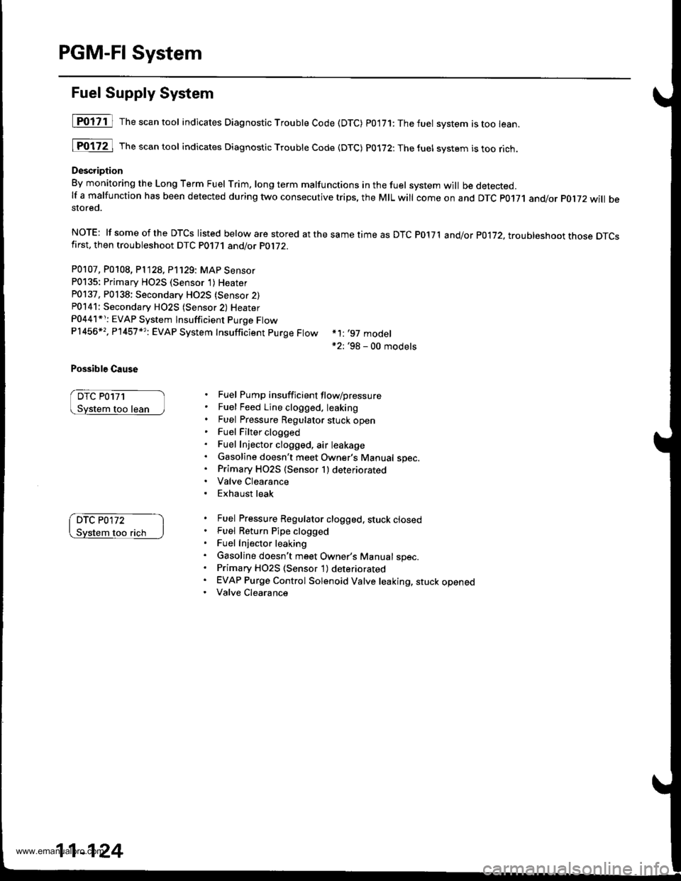
PGM-FI System
Fuel Supply System
[POliil The"""ntool indicates Diagnostic Troubte Code (DTC) p0'171:Thefuet system istoo lean.
[Fo17ZJ rh""""ntool indicates Diagnostic Troubte code {DTc) p0172:Thefuel svstem istoorich.
Description
By monitoring the Long Term Fuel rrim, long term malfunctions in the fuel system will be detected.lf a malfunction has been detected during two consecutive trips, the MIL will come on and DTc p0171 and/or pol72 will bestored.
NOTE: lf someof the DTCS listed below are stored atthesametimeas DTC P017'l and/or p0172, troubleshoot those DTcsfirst, then troubleshoot DTC P0171 and/or PO1i2.
P0107, P0108, P1128, P'1129: MAP Sensor
P0135: Primary HO2S (Sensor 1)Heater
P0137, P0138: Secondary HO2S {Sensor 2)P0141: Secondary H02S (Sensor 2) Heater
P0441*r: EVAP System lnsufficient Purge FtowP1456*,, P'l457 *?i EVAP System Insufficient purge Ftow
Possible Cause
DTC P0171
too lean
*1: '97 model*2: '98 - 00 models
Fuel Pump insufficient flow/pressure
Fuel Feed Line clogged. leaking
Fuel Pressure Regulator stuck openFuel Filter clogged
Fuel Injector clogged, air leakage
Gasoline doesn't meet Owner's Manual spec.Primary HO2S (Sensor 1) deteriorated
Valve Clearance
Exhaust leak
Fuel Pressure Regulator clogged, stuck closedFuel Return Pipe clogged
Fuel Injector leaking
Gasoline doesn't meet Owner's Manual spec.Primary H02S (Sensor 1) deteriorated
EVAP Purge Control Solenoid Valve leaking, stuck openedValve Clearance
DTC P0172
flch
11-124
www.emanualpro.com
Page 393 of 1395
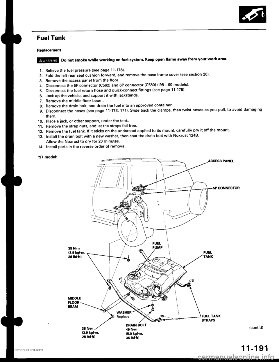
Fuel Tank
Replacement
1. Relieve the fuel pressure (see page 11-178).
2. Fold the left rear seat cushion forward, and remove the base frame cover {see section 20).
3. Remove the access panel from the floor.
4. Disconnect the 5P connector 1C562) and 6P connector (C580) ('98-00 models)'
5. Disconnect the fuel return hose and quick-connect fittings {see page 11-175}
6. Jack up the vehicle, and support it with jackstands.
7. Remove the middle floor beam.
8. Remove the drain bolt, and drain the fuel into an approved contaaner.
g. Disconnect the hoses (see page 11-173, 174). slide back the clamps. then twist hoses as you pull, to avoid damaging
them.
10. Place a jack, or other suppon, under the tank
11. Remove the strap nuts, and let the straps fall free
12. Remove the fuel tank. lf it sticks on the u ndercoat applied to its mount, carefu lly pry it off the mount,
'13. lnstallthe drain bolt with a new washer, then coat the drain bolt with Noxrust 1248'
Allow the Noxrust to dry for 20 minutes.
14. Install parts in the reverse order of removal.
'97 modol:AOCESS PANEL
CONNECTOR
@ Do not smoke while working on fuol systam Keep open flame away from your work area'
DRAIN EOLT49 N.m15.0 kgf'm,36 rbt frl
(cont'd)
1 1-191
www.emanualpro.com
Page 396 of 1395
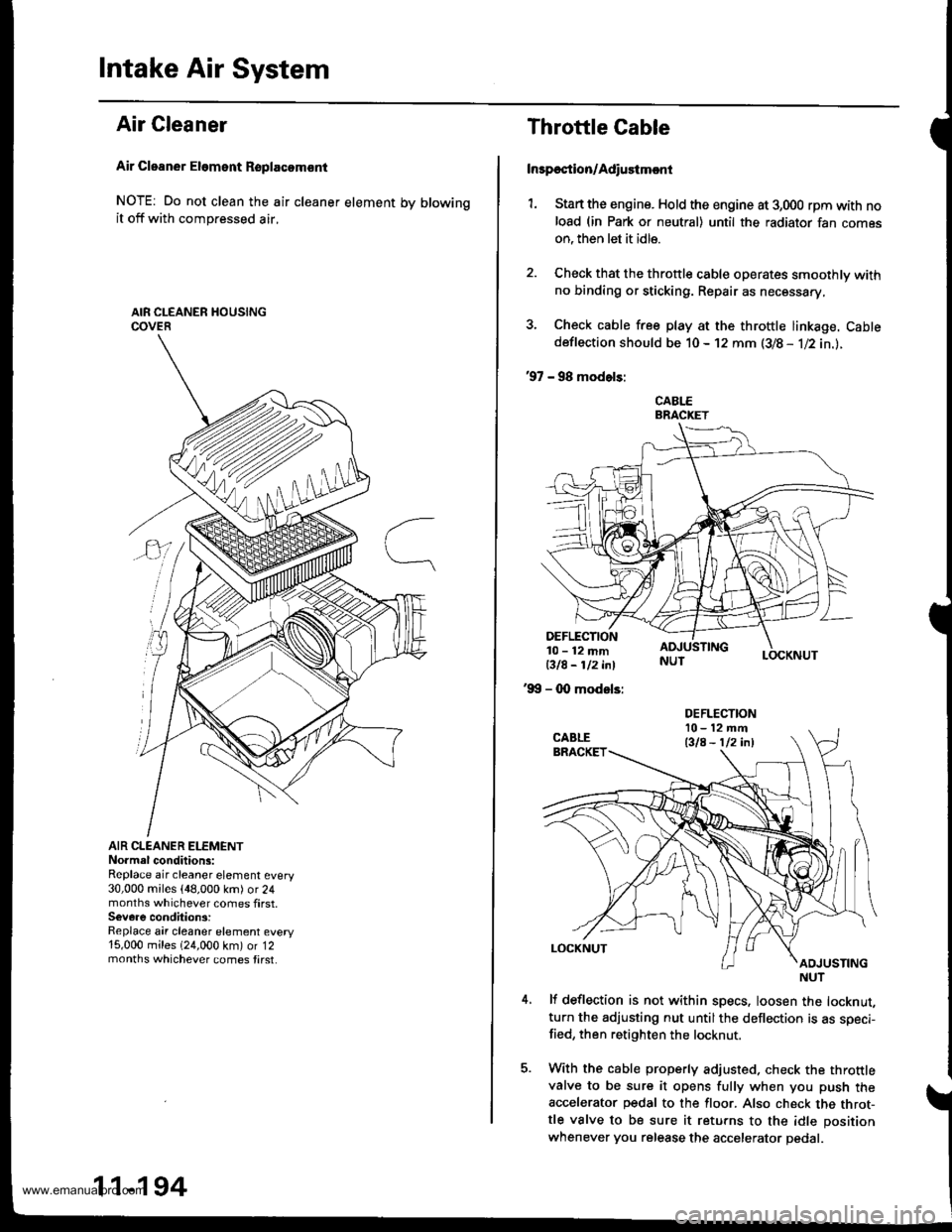
Intake Air System
Air Cleaner
Air Cleaner Eloment Rsplacomsnt
NOTE: Do not clean the air cleaner element by blowingit off with compressed air,
AIR CLEANER ELEMENTNo.mal conditions:Replace air cleaner element every30,000 miles {48,000 km) or 24months whichever comes first.Severe condition3:Replace air cleaner element every15,000 miles 124,000 km) or 12months whichever comes tirst.
m
11-194
Throttle Cable
Inrpection/Adiustmcnt
1. Stan the engine. Hold the engine at 3,000 rpm with noload (in Park or neutral) until the radiator fan comeson, then let it idle.
2. Check that the throttle cable operates smoothly withno binding or sticking. Repair as necessary,
3. Check cable free play at the throttle linkage. Cabtedeflection should be 10- 12 mm (3/8 - 1l2in.l.
'97 - 98 modols:
CABLEBRACKET
LOCKNUT
DEFLECTION10-12mmBIA- 112 i^l
'99 - 0O modsls:
lf deflection is not within specs, loosen the locknut,turn the adjusting nut untilthe deflection is as speci-fied, then retighten the locknut.
With the cable properly adjusted. check the throttlevalve to be sure it opens fully when you push theaccelerator pedal to the floor. Also check the throt-tle valve to be sure it returns to the idle position
whenever you release the accelerator pedal.
DEFLECTIONl0-12mft
Bla - 112 inl
NUT
www.emanualpro.com
Page 639 of 1395
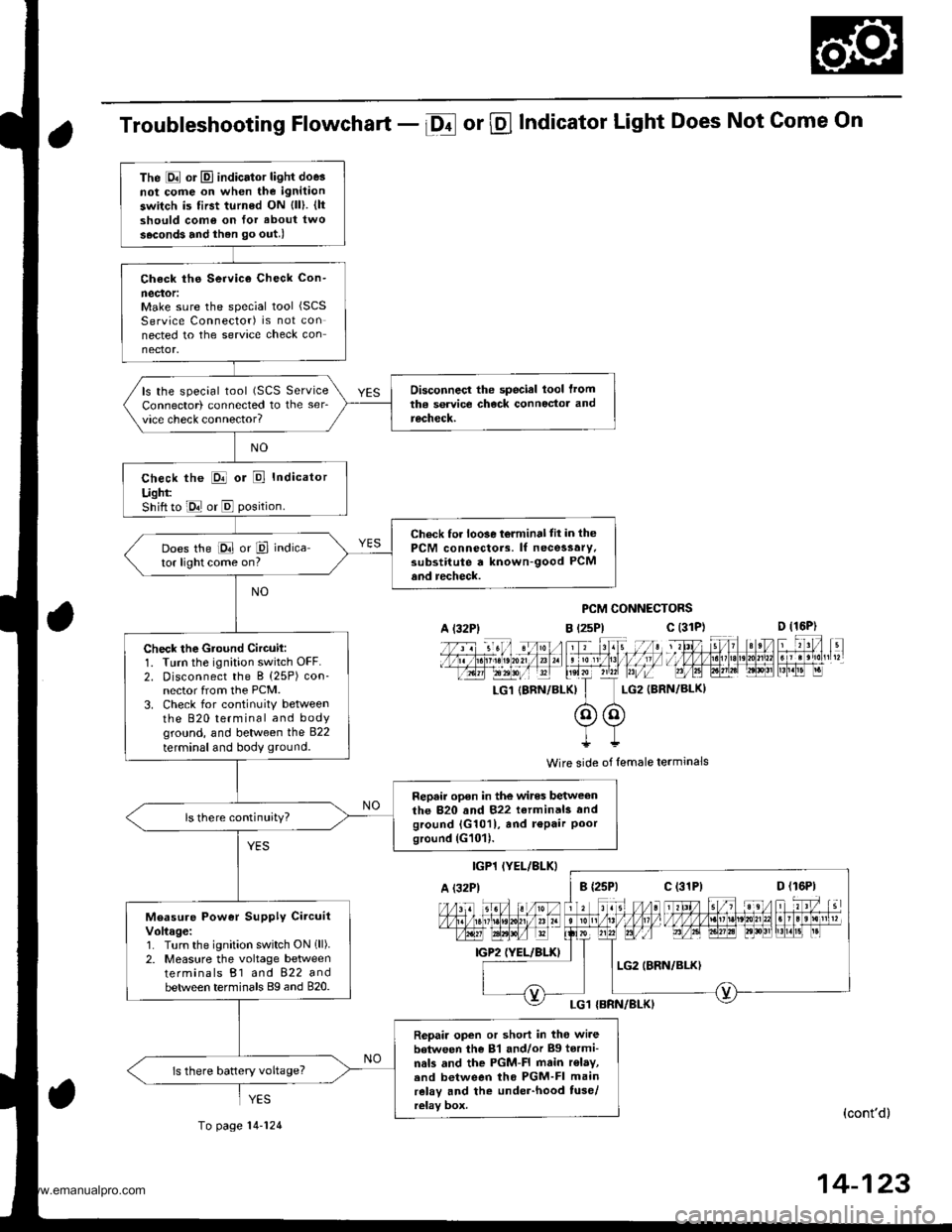
Troubleshooting Flowchart - Df or @ Indicator Light Does Not Come On
PCM CONNECTORS
B t2sPl c (31D (16P)
l*f4tr 8-
f - -- -6 3 rol ,: irr t lrpri$fe?0?r/a)1 e 'oI 13 11/ / l//|rrr I , ltelx ?r2? r,/i-T_LG1 {8RN/BI-KI I LG2 (BRN/BL()I
@@I++
Wire side of lemale terminals
(cont'd)
14-123
The E or El indicator light doe3not cofie on when the ignitaon
switch is first turned ON {ll). {ltshould como on for about two
s.cond3 and ihen go out.l
Check ths Service Check Con-
neclor:Make sure the special tool (SCS
Service Connector) is not connected to the service check connector.
Disconnecl the special lool lromtha service check connoctor andrecheck.
ls the special tool (SCS ServiceConnector) connected to the ser_vice check connector?
check the E or E Indicator
Ught:Shift to E or E position.
Check for loo3e t6lminal tit in thePCM connectors. lf necessary.substitute a known-good PCMand recheck.
Does the E or P indica-tor light come on?
Check the Gtound Circuil:1. Turn the ignition switch OFF.2. Disconnect the B (25P) con-nector from the PCM.3. Check for continuitY betweenthe 820 terminal and bodyground, and between the 822
terminal and body ground.
Repair open in the wires betweenthe 820 and 822 terminals andground {G1011, and r€Pair Poorground (G101).
ls there continuity?
Measure Power Supply CircuitVoltage:1. Turn the ignition switch ON 1ll).2. Measure the voltage betweenterminals B1 and 822 andbetween terminals Bg and 820.
Repair open or short in tho wi.ebetween the 81 and/or Bg tormi-nals and the PGM-FI main r€lay,.nd between tho PGM-FI mainrelay and the under-hood tuse/relay box.
ls there battery voltage?
A l32Plc (31P)
c (31P)
YES
To page 14-124
www.emanualpro.com
Page 640 of 1395
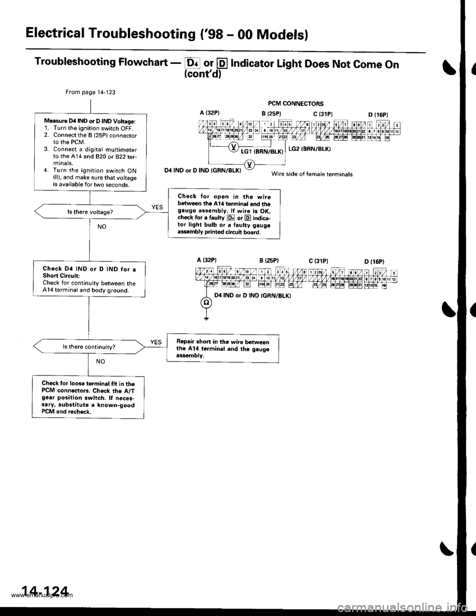
Electrical Troubleshooting ('98 - 00 Modelsl
Troubleshooting Flowchart - E or @ Indicator Light Does Not come on(cont'd)
PCM CONNECTORS
B {25P} C (3D (16P1
n f,-ff nt f,Fjrti.trnnmflnr
D4 INO or D IND IGRN/BLKI
From page 14-123
Measure D4IND or D lNDVoh.ge:'L Turn the ignition switch OFF.2. Connect the B (25Plconnector
to the PCM.3. Connect a djgital multimeterto the A14 and 820 or B22 terminals,4. Turn the ignition switch ON(ll), and make sure that voltageis available for two seconds.
Check lor open in the wireb€tween the Al/t terminal .nd thegeugo a$eftbly. lf wi.a is OK.check tor a fautty E or E indica-tor light bulb or a faulty gaugeass€mbly p.inted circuit board.
Check D4 IND or D IND for aShort CircuitiCheck for continuity between theA14 terminal and body ground.
Ropair short in tha wiro b€twesnthe A14 termin.l and th€ gaugo.ssemblv.
Check tor looso telminal tit in thePCM connoctors. Chock the A/Tgear position swiich. It neces-3ary, substitute a known-goodPCM and rech€ck.
c (31P)
LG2 (BRN/BLKI
Wire side of female terminals
D {16P)
D4 IND or D IND
14-124
www.emanualpro.com