6-3 HONDA CR-V 1999 RD1-RD3 / 1.G Workshop Manual
[x] Cancel search | Manufacturer: HONDA, Model Year: 1999, Model line: CR-V, Model: HONDA CR-V 1999 RD1-RD3 / 1.GPages: 1395, PDF Size: 35.62 MB
Page 114 of 1395
Cylinder Head/Valve Train
Speciaf Tools .............6-2
Valve Clearance
Adiustment ............6-3
Valve Seals
Replacement (cylinder head
removal not requiredl ................. 6-5
Crankshaft Pulley and Pulley Bolt
Replacement .........6-7
Timing Belt
I llustrated lndex ............................... 6-8
Inspection ............., 6-9
Tension Adjustment ........................ 6-9
Removal ...........,..... 6-10
lnstallation .............6-11
Crankshaft Speed Fluctuation (CKFI
Sensor
Replacement .........6-13
Cylinder Head
lllustrated lndex ............................... 6-14
Removal .................6-16
Warpage ................6-27
lnstallation ............. 6-30
Camshafts
lnspection ..............6-22
Valves, Valve Springs and Valve Seals
Removal ................, 6-23
lnstallation ............. 6-29
Valve Guides
Valve Movement ............,,,,.,............ 6-25
Replacement .........6-25
Reaming .................6-27
Valve Seats
Reconditioning ......6-28
www.emanualpro.com
Page 116 of 1395
Valve Clearance
Adiustment
Adjust the valves only when the cylinder head tempera-
ture is less than 100"F (38"C).
1. Remove the cylinder head cover.
Remove the middle cover (see page 6-11).
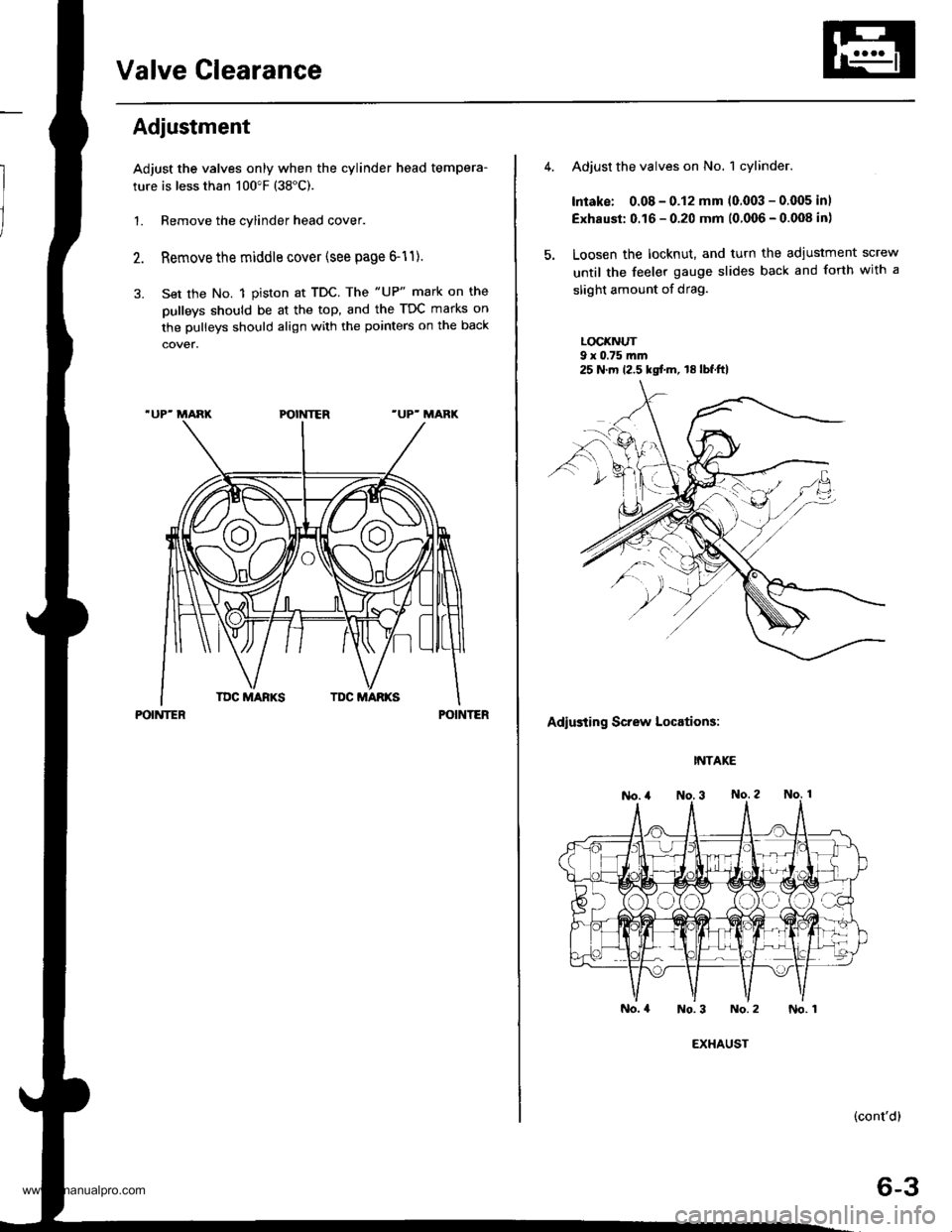
Set the No. 1 piston at TDC. The "UP" mark on the
pulleys should be at the top, and the TDC marks on
the pulleys should align with the pointers on the back
POINTERPOINTER
Adjust the valves on No. 1 cylinder.
Intake: 0.08 - 0.12 mm (0.003 - 0.005 inl
Exhaust: 0.16 - 0.20 mm (0.006 - 0.008 in)
Loosen the locknut, and turn the adiustment screw
until the feeler gauge slides back and forth with a
slight amount of drag.
LOCI(NUT9 x 0.75 m.n
Adiusting Screw Locations:
INTAKE
No.4 No.3 No.2
(cont'd)
6-3
25 N.m 12.5 kgf.m, 18lbf.ft)
EXHAUST
No. 1
www.emanualpro.com
Page 117 of 1395
Valve Clearancev
Adjustment (cont'dl
6. Tighten the locknut, and check the clearance agajn.
Repeat the adjustment if necessary.
GAUGE
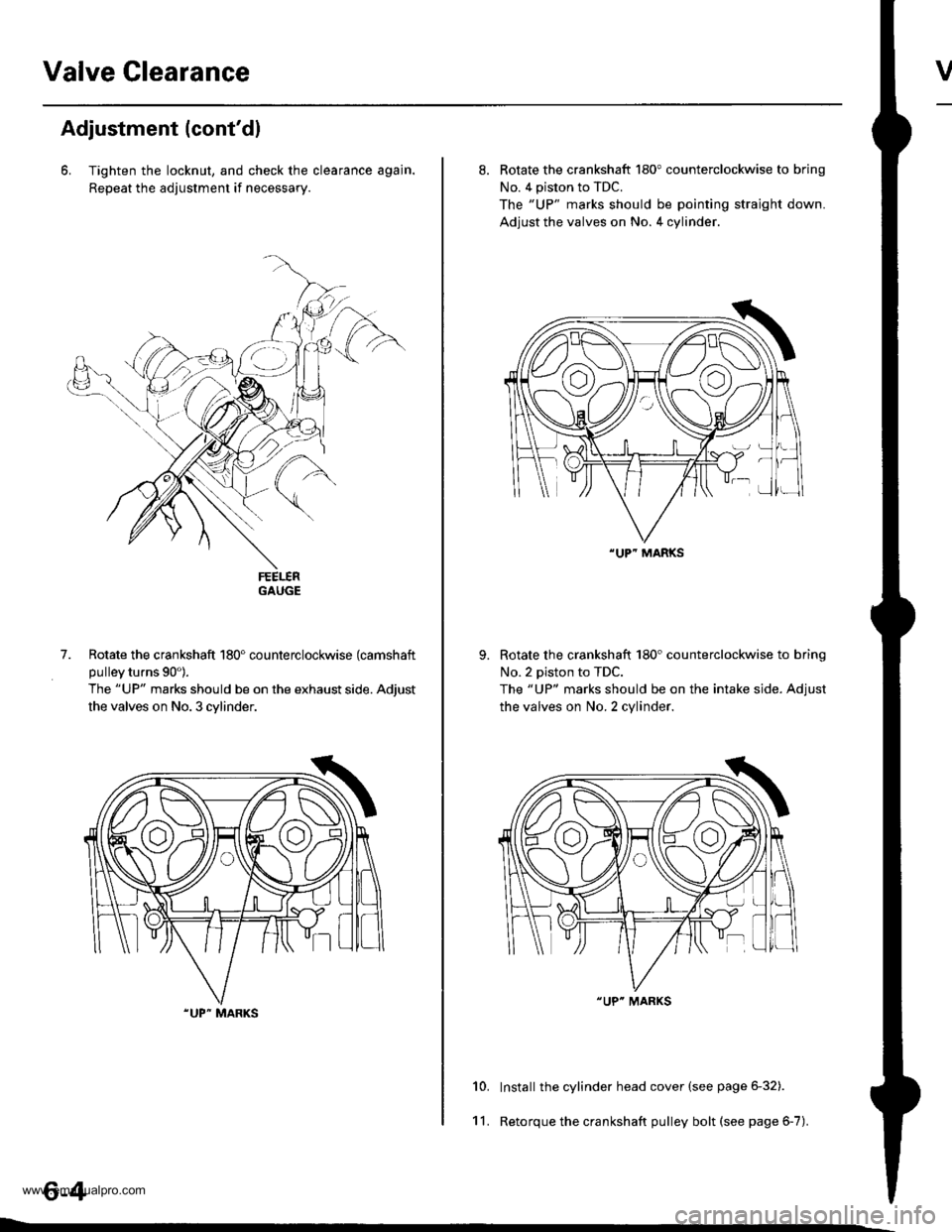
Rotate the crankshaft 180" counterclockwise (camshaft
pulley turns 90').
The "UP" marks should be on the exhaust side. Adjust
the valves on No. 3 cylinder.
.UP" MARKS
7.
8. Rotate the crankshaft 180" counterclockwise to brinq
No. 4 piston to TDC.
The "UP" marks should be pointing straight down.
Adjust the valves on No. 4 cylinder.
Rotate the crankshaft 180'counterclockwise to brino
No.2 piston to TDC.
The "UP" marks should be on the intake side. Adiust
the valves on No. 2 cylinder.
Install the cylinder head cover (see page 6-32).
Retorque the crankshaft pulley bolt (see page 6-7).
10.
11.
"UP" MARKS
"UP" MARKS
www.emanualpro.com
Page 121 of 1395
Timing Belt
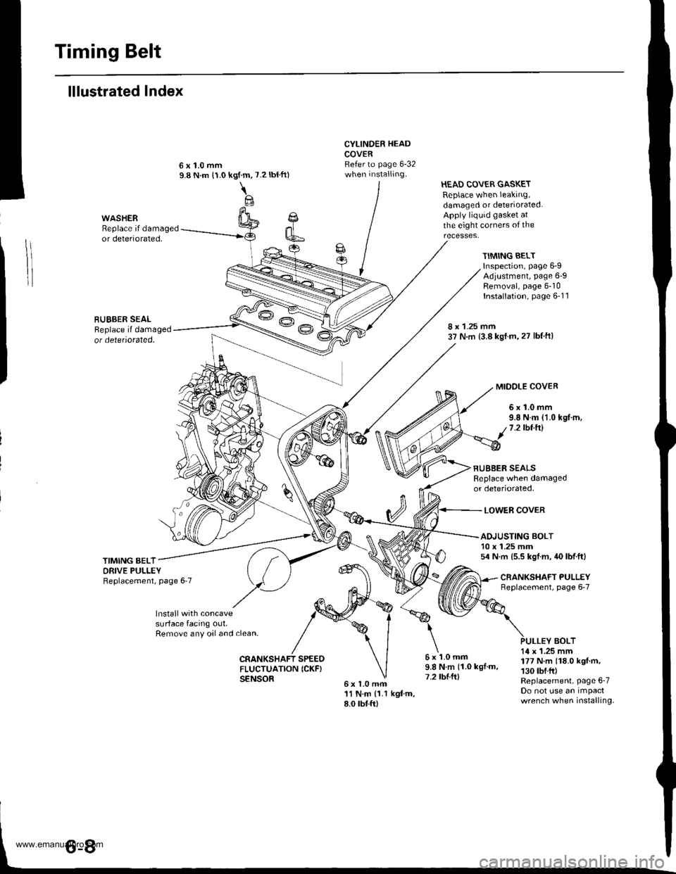
lllustrated Index
Cl
k6
CYLINDER HEADCOVERRefer to page 6-32when installing.
6x1.0mfi11 N.m {1.1 kgtm,8.0 rbtft)
HEAD COVER GASKETReplace when leaking,damaged or deteriorated.Apply liquid gasket atthe eight corners of theWASHERReplace if damagedor deteriorated,
RUEBER SEALReplace il damagedot detetiorated.
kgf.m,
\@
7.2 tbtft)
TIMING BELTInspection, page 6-9Adjustment, page 6-9Removal, page 6-10Installation, page 6-1 1
8 x 1.25 mm37 N.m (3.8 kst.m,27 lbf ftl
MIDOLE COVER
6x1.0mm9.8 N.m {1.0 kgf.m,1.2lbt.ftl
RUBBER SEALSReplace when damagedor deteriorated,
LOWER COVER
TIMING BELTORIVE PULLEYReplacement, page 6'7
ADJUSTING BOLT10 x 1.25 mm54 N.m (5.5 kgl.m, 40 lbf.ft)
CNANKSHAFT PULLEYneplacement, page 6-7
lnstall with concavesurface facing out,Remove any oal and clean,BOLT
CRANKSHAFT SPEEOFLUCTUATION ICKF}SENSOR
6x1.0mm9.8Nm(1.0kgl.m,7.2 tbl.ft)
14 x 1.25 mm177 N.m (18.0 kgf'm,130 tbf.fr)Replacement, Page 6-7Do not use an impactwrench when installing.
www.emanualpro.com
Page 122 of 1395
1.
2.
Inspection
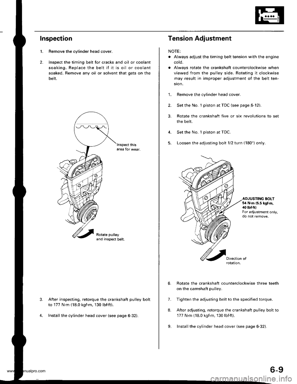
Remove the cylinder head cover.
lnspect the timing belt for c.acks and oil or coolant
soaking. Replace the belt if it is oil or coolant
soaked. Remove any oil or solvent that gets on the
belt.
lnspect thisarea for wear.
After inspecting, retorque the crankshaft pulley bolt
to 177 N.m (18.0 kgnm, 130 lbf.ft).
Install the cylinder head cover (see page 6-32).
3.
Tension Adjustment
NOTE:
. Always adjust the timing belt tension with the engine
coto.
. Always rotate the crankshaft counterclockwise when
viewed from the pulley side. Rotating it clockwise
may result in improper adiustment of the belt ten-
sion.
'1. Remove the cylinder head cover
2. Set the No. 1 piston at TDC (see page.6-12).
3. Rotate the crankshaft five or six revolutions to set
the belt.
Set the No. 1 piston at TDC.
Loosen the adjusting bolt 1/2 turn (180') only.
4.
5.
ADJUSTING BOLT5,4 N.m (5.5 kgf.m,40 tbtftlFor adiustment only,
7.
8.
Rotate the crankshaft counterclockwise three teeth
on the camshaft pulley.
Tighten the adjusting bolt to the specified torque.
After adjusting, retorque the crankshaft pulley bolt to
177 N.m (18.0 kgf.m, 130 lbf.ft).
Installthe cylinder head cover (see page 6-32).9.
rotation,
6-9
www.emanualpro.com
Page 124 of 1395
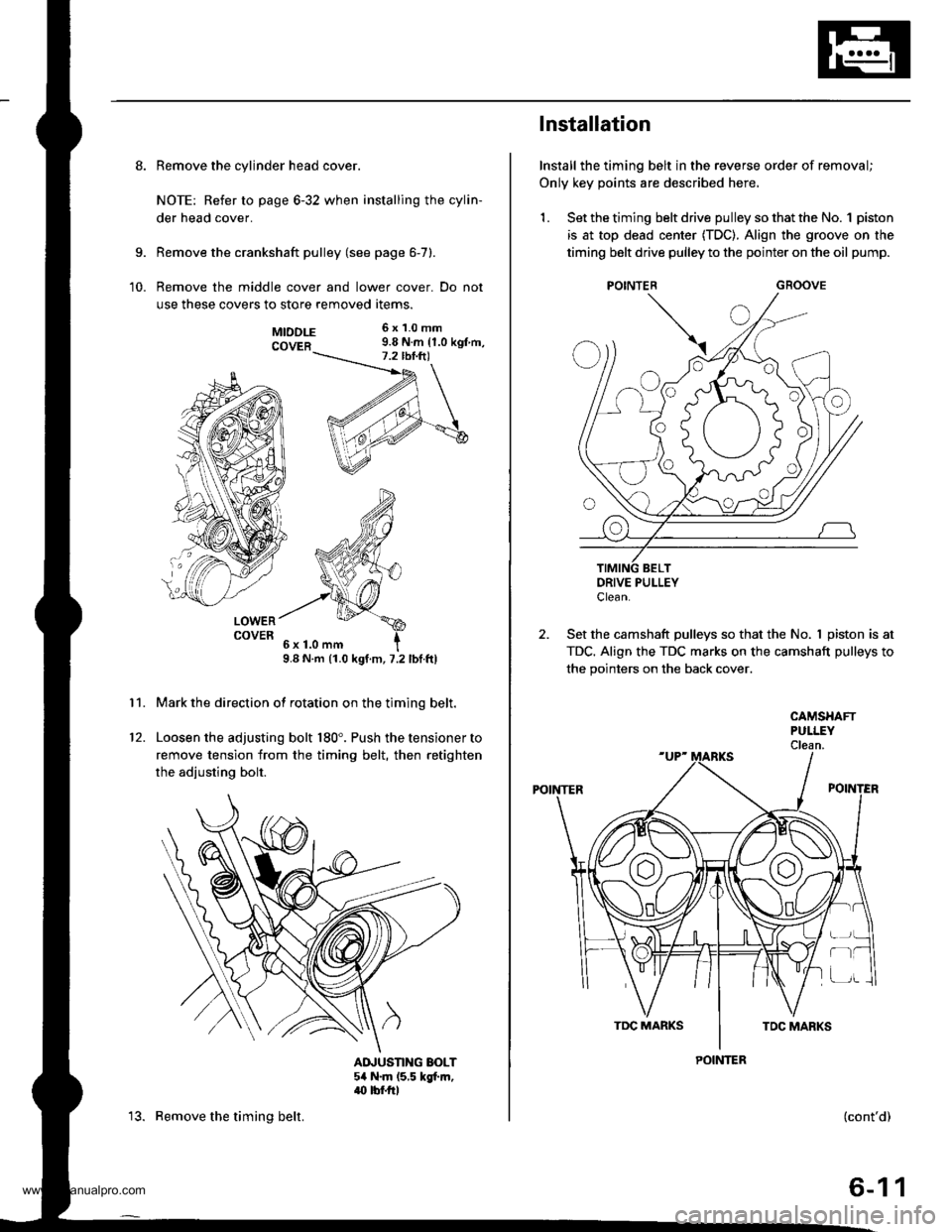
8. Remove the cylinder head cover.
NOTE: Refer to page 6-32 when installing the cylin-
der head cover.
Remove the crankshaft pulley (see page 6-7).
Remove the middle cover and lower cover. Do not
use these covers to store removed items.
9.
10.
11.
MTDDLE 6x1.0mm
COVER 9.8 N.m {1.0 kgt m,
LOWERCOVER
9.8 N.m (1.0 kgt.m, 7.2 lbf.ftl
Mark the direction of rotation on the timing belt.
Loosen the adjusting bolt 180'. Push the tensioner to
remove tension from the timing belt, then retighten
the adiusting bolt.
AINUSTING BOLT54 N.m (5,5 kgt m,.(} tbf.rrl
12.
13. Remove the timing belt.
Installation
Install the timing belt in the reverse order of removal;
Only key points are described here,
1. Set the timing belt drive pulley so that the No. 1 piston
is at top dead center (TDC). Align the groove on the
timing belt drive pulley to the pointer on the oil pump.
GROOVE
DRIVE PULLEYClean.
2. Set the camshaft pulleys so that the No. I piston is at
TDC. Align the TDC marks on the camshaft pulleys to
the pointers on the back cover.
POINTER
CAMSHAFTPULLEYClean.
POINTER
r-t
(cont'd)
6-11
www.emanualpro.com
Page 125 of 1395
Timing Belt
Installation (cont'd)
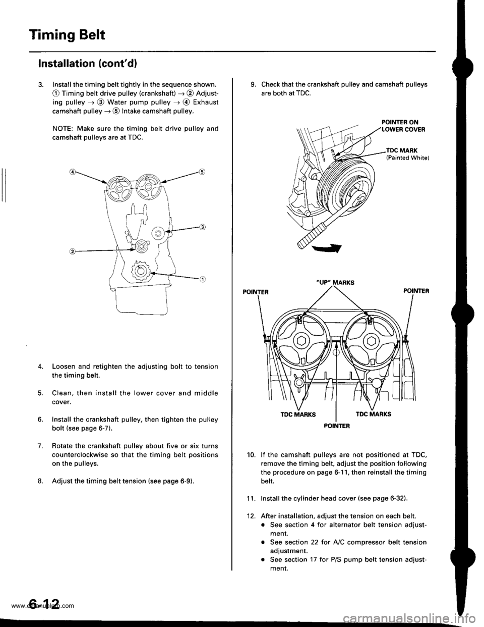
3. Install the timing belt tightly in the sequence shown.
O Timing belt drive pulley (crankshaft) J @ Adjust-
ing pulley =r @ Water pump pulley r @ Exhaust
camshaft pulley --) @ Intake camshaft pulley.
NOTE: Make sure the timing belt drive pulley and
camshaft pulleys are at TDC.
4. Loosen and retighten the adjusting bolt to tension
the timing belt.
5. Clean. then install the lower cover and middle
cover.
Install the crankshaft pulley, then tighten the pulley
bolt (see page 6-7).
Rotate the crankshaft pulley about five or six turns
counterclockwise so that the timing belt positions
on the pulleys.
Adjust the timing belt tension {see page 6-9).
1.
6-12
9. Check that the crankshaft pulley and camshaft pulleys
are both at TDC.
POINTER ON
lf the camshaft pulleys are not positioned at TDC,
remove the timing belt. adjust the position following
the procedure on page 6-11. then reinstall the timing
belt.
Installthe cylinder head cover (see page 6-32).
After installation, adjust the tension on each belt.
. See section 4 for alternator belt tension adjust-
menr.
. See section 22 for NC compressor belt tension
adjustment.
. See section 17 for P/S pump belt tension adjust-
ment.
10.
11.
12.
POINTER
www.emanualpro.com
Page 128 of 1395
-?E
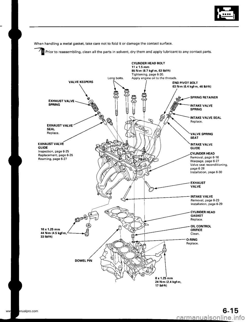
handling a metal gasket. take care not to fold it or damage the contact surface.
Prior to reassembling, clean all the parts in solvent, dry them and apply lubricant to any contact parts.
CYLINDER HEAD BOLT11 x 1.5 mm85 N.m {8.7 kgf.m,6:} lbf.ft)Tightening, page 6'30.Apply engine oilto the threads.VALVEKEEPERS
\
END PIVOT BOLT63 N.m 16.4 kgl m, 46 lbf.ft)
EXHAUSY VALVESEALReplace.
EXHAUST VALVEGUIDEInspection, page 6-25Replacem6nt, page 6-25Reaming, page 6-27
10 x 1.25 mm4,0 N.m {i1.5 kgf.m.33 rbf.ft)
GASKETReplace.
OIL CONTROLORIFICEClean.
EXHAUST VALVESPRING
SPRING BETAINER
INTAKE VALVESPRING
INTAKE VALVE SEALReplace.
VALVE SPRINGSEAT
INTAKE VALVEGUIDE
Removal, page 6-16Warpage, page 6 27Valve seat reconditioning,page 6 28Installation, page 6-30
EXHAUSTVALVE
INTAKE VALVERemoval, page 6-23Installation, page 6-29
CYLINDER HEAO
HEAD
O.RINGReplace.
8 x 1.25 mm24 N.m (2.4 kgf.m,17 tbf.ft)
DOWEL PIN
6-15
www.emanualpro.com
Page 135 of 1395
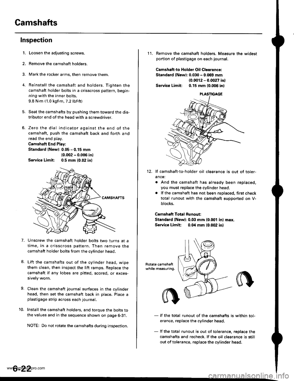
Camshafts
4.
Inspection
1.
7.
Loosen the adjusting screws.
Remove the camshaft holders.
Mark the rocker arms, then remove them.
Reinstall the camshaft and holders. Tighten the
camshaft holder bolts in a crisscross pattern, begin-
ning with the inner bolts.
9.8 N.m (1.0 kgf.m.7.2 lbf.ft)
Seat the camshafts by pushing them toward the dis-
tributor end of the head with a screwdriver.
Zero the dial indicator against the end of the
camshaft, push the camshaft back and forth and
read the end play.
Camshaft End Play:
Standard lNewl: 0.05 - 0.15 mm
10.002 - 0.005 in)
Service Limit: 0.5 mm (0.02 in)
Unscrew the camshaft holder bolts two turns at a
time, in a crisscross pattern, Then remove the
camshaft holder bolts from the cvlinder head.
Lift the camshafts out of the cylinder head. wipe
them clean, then inspect the lift ramps, Replace the
camshaft if any lobes are pitted, scored, or exces-
sively worn.
Clean the camshaft journal surfaces in the cylinder
head, then set the camshaft back in Dlace. Place aplastigage strip across each journal.
Install the camshaft holders. and torque the bolts tothe values and in the sequence shown on page 6-31.
NOTE: Do not rotate the camshafts during inspection.
8.
10.
6-22
11. Remove the camshaft holders. Measure the widest
portion of plastigage on each journal.
Camshatt-to HoldGr Oil Clearance:
Standard {Newl: 0.030 - 0.069 mm
{0.0012 - 0.0027 in}
Servico Limit: 0.15 mm (0.006 in)
12. lf camshaft-to-holder oil clearance is out of toler-
ance:
. And the camshaft has already been replaced,
you must replace the cylinder head.. lf the camshaft has not been replaced, first check
total runout with the camshaft suoDorted on V-
blocks.
Camshaft Total Runout:
Standard (N6w): 0.03 mm (0.001 in) max.
Service Limit 0.04 mm (0.(X)2 in)
Rotat6 camshattwhile measuring.
- lf the total runout of the camshafts is within tol-
erance, replace the cylinder head
- lf the total runout is out of tolerance, replace the
camshafts and recheck. lf the oil clearance is still
out of tolerance, replace the cylinder head.
www.emanualpro.com
Page 143 of 1395
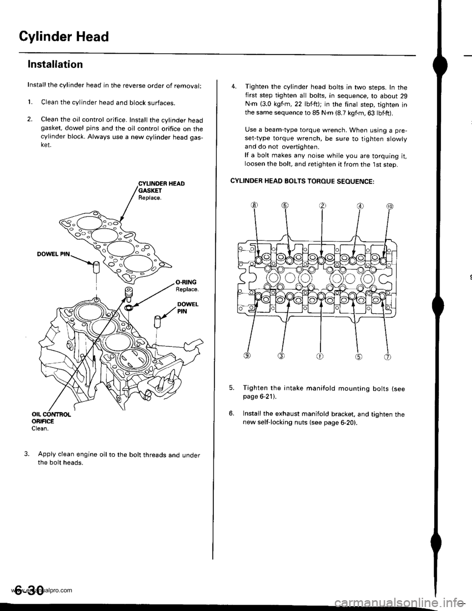
Cylinder Head
Installation
Installthe cylinder head in the reverse order of removal:
1. Clean the cylinder head and block surfaces.
2. Clean the oil control orifice. Install the cylinder headgasket, dowel pins and the oil control orifice on thecylinder block. Always use a new cylinder head gas-ket.
CYLII{DER HEADGASKETR€place.
DOWEL PIN
O.RINGRoplace.
DOWELPIN
OIL CONTBOLORIFICEClean.
Apply clean engine oil to the bolt threads and underthe bolt heads.
4. Tighten the cylinder head bolts in two steps. In thefirst step tighten all bolts, in sequence, to about 29
N.m {3.0 kgf.m,22 lbf.ft); in the finat step, tighten inthe same sequence to 85 N.m (8.7 kgf.m,63 lbf.ft).
Use a beam-type torque wrench. When using a pre-
set-type torque wrench, be sure to tighten slowly
and do not overtighten.
lf a bolt makes any noise while you are torquing it,loosen the bolt, and retighten it from the 1st step.
CYLINDER HEAD BOLTS TOROUE SEOUENCE:
Tighten the intake manifold mounting bolts (see
page 6-21).
Install the exhaust manifold bracket. and tighten thenew self-locking nuts (see page 6-20).
6-30
www.emanualpro.com