Dashboard assembly HONDA CR-V 1999 RD1-RD3 / 1.G Workshop Manual
[x] Cancel search | Manufacturer: HONDA, Model Year: 1999, Model line: CR-V, Model: HONDA CR-V 1999 RD1-RD3 / 1.GPages: 1395, PDF Size: 35.62 MB
Page 41 of 1395

Lubrication Points
For the details of lubrication points and type of lubricants to be applied. refer to the illustrated index and various work pro-
cedures (such as Assembly/Reassembly, Replacement, Overhaul, Installation, etc.) contained in each section.
Recomm6nded Engine OilEngine oil viscosity for ambient temperature ranges
100'F
-30 -20 .10 0 10 20 30 40'c
r1: Always use Genuine Honda Manual Transmission Fluid {MTF). Using motor oil can cause stiffer shifting because it
does not contain the orooer additives.*2: Always use Genuine Honda Premium Formula Automatic Transmission Fluid (ATF). Using a non-Honda ATF can affect
shift qualitv.+3r Always use Genuine Honda DOT 3 Brake Fluid. Using a non-Honda brake fluid can cause corrosion and decrease the
life of the system.*4: Always use Genuine Honda Power Steering Fluid. Using any other type of power steering fluid or automatic transmis-
sion fluid can caused increased wear and poor steering in cold weather.
API SERVICE LABEL
/,.*-G\
/.'z-\e\t/6AE\ll-;-1 5w-30 /---l
w
API CERTIFICATION SEAL
ffi-20 0 20
NO.LUBRICATION POINTSLUBRICANT
EngineAPI Service Grade: Use SJ "Energy Conserving" grade oil. The oilcontainer may also display the API Certitication seal shownbelow. Make sure it says "For Gasoline Engines." SAE vjscosity:See chart below.
2
TransmissionManualGenuine Honda MTF*1
AutomaticGenuine Honda Premium Formula Automatic Transmission Fluid(ATF)*'
3Rear differentialGenuine Honda CVT Fluid
4Brake line (includes ABS line)Genuine Honda DOT 3 Brake Fluid*3
5Clutch LineBrake fluid DOT 3 or DOT 4*3
6Shift lever pivots (Manual transmission)Grease with molybdenum disultide
1Release fork (Manual transmission)LJrea Grease UM264 P/N 4'1211 - PYs - 305
IPower steering gearboxSteering grease P/N 08733 - B070E
Throttle cable end {Dashboard lower panel holelSilicone grease
10l112
14
Throttle cable end (Throttle link)Brake master cylinder pushrodPedal linkageBattery terminalsFuelfill lidClutch master cylinder pushrod
Multi purpose grease
1617181920
Hood hinges and hood lockTailgate hingesHatch glass hingesDoor hinges, upper and lowerDoor opening detent
Honda White Lithium Grease
21
22
Caliper Piston seal, Dust seal,Caliper pin, PistonShilt cable and select cable {Manual transmission)Silicone grease
23Brake line ioints (Front and rear wheelhouse)Rust preventives
24Power steering systemGenuine Honda Power Steering Fluid-.
25Air conditioning compressorCompressor oil: SP 10 lP/N 38897 - P13 - A0lAH or38899-P13-A01)For Refrigerant: HFC 134a (R,134a)
3-2
www.emanualpro.com
Page 519 of 1395

Description
General Operation
The Automatic transmission is a 3-element torque converter and triple-shaft electronically controlled unit which provides 4
speeds forward and 1 reverse speed The unit is positioned in line with the engine'
There are two tvoes of automatic transmission on CR-V; the four-wheel drive (4WD) model ('97 - 00)' and the front-wheel
drive (2WD) model ('98 - 00).
Toroue Converter, G€ars, and Clutches
The torque converter consists of a pump. turbine. and stator assembly in a single unit. The torque converter is connected to
the engine crankshatt. These parts turn together as a unit as the engine turns. Around the outside of the torque converter is
a ring gear which meshes with the starter pinion when the engine is started. The torque converter assembly serves as a fly-
wheel while transmitting power to the transmission mainshaft.
The transmission has three parallel shafts: the mainshaft. the countershaft, and the sub-shaft. The mainshaft is in line with
the engine crankshaft. The mainshaft includes the 1st, 2nd. and 4th clutches, and gears lor 3rd,2nd,4th. reverse and 1st
(3rd gear is integral with the mainshaft, while reverse gear is integral with the 4th gear). The countershaft includes the 3rd
clutch and gears for 3rd,2nd, 4th, reverse, 1st, and park. Reverse and 4th gears can be locked to the countershaft at its cen-
ter, providing 4th gear or reverse, depending on which way the selector is moved. The sub-shaft includes the lst-hold
clutch and gears for lst and 4th.
The gears on the mainshaft are in constant mesh with those on the countershaft and sub-shaft. When certain combinations
of gears are engaged by the ctutches, power is transmitted from the mainshaft to the countershaft to provide E, D!, tr, tr,
and E position ('97 - 98 models). and E. E, E, and E position ('99 - 00 models)'
Electlonic Control
The electronic controt system consists of the Powenrain Control Module (PCM), sensors, a linear solenoid, and four
solenoid valves. Shifting and lock-up are electronically controlled for comfortable driving under all conditions. The PCM is
located below the dashboard, under the kick panel on the passenger's side.
Hydraulic Control
The valve bodies include the main valve body, the secondary valve body, the regulator valve body, the servo body, and
the lock up valve body. They are bolted to the torque converter housing. The main valve body contains the manual valve,
the 1-2 shift valve, the 2nd orifice control valve. the CPB {Clutch Pressure Back-up) valve, the modulator valve, the servo
control valve. the relief valve, and ATF pump gears. The secondary valve body contains the 2-3 shift valve, the 3-4 shift
valve, the 3,4 orifice control valve. the 4th exhaust valve and the CPC (Clutch Pressure Control) valve. The regulator valve
bodv contains the pressure regulator valve, the torque converter check valve, the cooler relief valve, and the lock-up con-
trol valve. The servo body contains the servo valve which is integrated with the reverse shift tork, and the accumulators
The lock-up valve body contains the lock-up shift valve and the lock-up timing valve. The linear solenoid and the shift con-
trol solenoid valve Ay'B are bolted to the outside of the transmission housing, and the lock-up control solenoid valve Ay'B is
bolted to the outside of the torque converter housing. Fluid trom the regulator passes through the manual valve to the
various control valves. The clutches receive fluid from their respective feed pipes or internal hydraulic circuit
ShiftControl Mechanism
input from various sensors located throughout the vehicle determines which shift control solenoid valve the PCM will acti-
vate. Activating a shift control solenoid valve changes modulator pressure, causing a shift valve to move. This pressurizes
a line to one of the clutches. engaging that clutch and its corresponding gear. The shift control solenoid valves A and B are
controlled by the PCM.
Lock-up Mechanism
tn E! position (,97 - 98 modets) and in E position ('99 - O0 models), in 3rd and 4th, and in Del position in 3rd ('97 - 98
models) and in El position with Over,Drive (O/D) is OFF (by pressing rhe O/D switchl in 3rd ('99 - 00 models), pressurized
fluid is drained from the back of the torque converter through a fluid passage, causing the lock-up piston to be held
against the torque converter cover, As this takes place, the mainshaft rotates at the same speed as the engine crankshaft.
Together with hydraulic control, the PcM optimizes the timing of the lock-up mechanism The lock-up valves control the
range of lock-up according to lock-up control solenoid valves A and B, and the linear solenoid. When lock-up control
solenoid valves A and B activate, the modulator pressure changes. The lock-up control solenoid valves A and B and the
linear solenoid are controlled by the PCM.
{cont'd)
14-3
www.emanualpro.com
Page 658 of 1395

A/T Gear Position Indicator
1.
f nput Test -'97 - 98 Models
Remove the gauge assembly from the dashboard (see section 20). and disconnect the 14P connector from the gauge
assemblv (see section 23),
Inspect the connector and socket terminals to be sure they are all making good contact.
. lf the terminals are bent, loose, or corroded, repairthem as necessary, and recheck the system.. lf the terminals look OK, make the following input tests at the 14P connector.- lf I test indicates a problem, find and correct the cause, then recheck the system.- lf all the input tests prove OK, but the indicator is faulty. replace the printed circuit board,
GAUGE ASSEMBLY 14P CONNECTOR
Wire side of female terminals
CavityWirs
ColorTest ConditionTest: Desir€d ResultPossible Cause
{lf rosult is not obtainod)
YEL
lgnition switch ON (ll)Check for voltage to ground:
There should be battery voltage,
. Blown No. 25 (7.5 A) fuse in the
under-dash fuse/relay box. An open in the wire
RE D/BLKCombination light
switch ON and dash
lights brightness con-
trol dial on full bright
Check for voltage between No. 2
and No. 3 terminals;
There should be battery voltage.
Blown No. 47 (7.5 A) fuse in the
under-dash fuse/relay box
Faulty combination Iight switch
Faulty dash iight brightness
controller
An open in the wire
RED
4BLUShift lever in ECheck for continuity to ground:
There should be continuity.
NOTE: There should be no continu-
ity in any other shift lever position.
' Faulty Ay'T gear position switch. An open in the wireBRNShift lever in E
7YELShift lever in @
8BLKUnder all conditionsCheck for continuity to ground:
There should be continuity
. Poor ground {G401). An open in the wire
9GRN/BLK
lgnition switch ON {ll)
and shift lever in any
position except E
Check for voltage to ground:
There should be battery voltage
for two seconds after the ignition
switch is turned ON {ll), and less
than 1 V two seconds later,
' Faulty PCM. An open in the wire
10GRNShift lever in ECheck for continuity to ground:
There should be continuity.
NOTE: There should be no conti-
nuity in any other shift lever posi-
UOn.
. Faulty A,ff gear position switch. An open in the wire1'lREDShift lever in @
12WHTShift lever in E
BLVBLU
Shift lever in ENOTE: Do not push
the brake pedal.
14LT GRN
lgnition switch ON { ll)
and shift lever in any
position except E and
E
Check for voltage to ground:
There should be about 5 V.
. Faulty PCM. An open in the wire
14-142
www.emanualpro.com
Page 659 of 1395

L
Input Test -'99 - 00 Models
Remove the gauge assembly from the dashboard {see section 20), and disconnect the 14P connector from the gauge
assembly (see section 23).
Inspect the connector and socket terminals to be sure they are all making good contact.
a lf the terminals are bent. loose, or corroded. repair them as necessary. and recheck the system.
. lf the terminals look OK, make the following input tests at the 14P connector.- lf a test indicates a problem, find and correct the cause, then recheck the system.- lf all the input tests prove OK, but the indicator is faulty, replace the printed circuit board.
GAUGE ASSEMBLY 14P CONNECTOR
Wire side of female terminals
CavityWire
ColorTest ConditionTest: Desired ResuhPossible Caus6
{lf resutt is not obtainod)
1YEL
lgnition switch ON (ll)Check for voltage to ground:
There should be battery voltage.
. Blown No.25 (7.5 A) fuse in the
under-dash fuse/relay box. An open in the wire
2RE D/BLK
Combination light
switch ON and dash
lights brightness con-
trol dial on full bright
Check for voltage between No. 2
and No.3 terminals:
There should be battery voltage.
Blown No. 47 {7.5 A) fuse in the
under-dash fuse/relay box
Faulty combination light switch
Faulty dash light brightness
controller
An open in the wire
5RED
BRNShift lever in ECheck for continuity to ground:
There should be continuity.
NOTE: There should be no continu-
ity in any other shift lever position.
. Faulty A/T gear position switch. An open in the wire7YELShift lever in E
'10BLUShift lever in E
LT BLU
lgnition switch ON (ll),
shift lever in E. and
Over-Drive is OFF bypressing O/D switch.
Check for continuity to ground:
There should be continuity.
Faulty O/D switch
Faulty A/T gear position switch
Faulty PCM
An open in the wire
8BLKUnder all conditionsCheck for continuity to ground:
There should be continuity
. Poor ground (G401)
. An open in the wire
9a:FI\|/Et| ta
lgnition switch ON (ll)
and shift lever in any
position except E
Check for voltage to groundl
There should be battery voltage
for two seconds after the ignition
switch is turned ON (ll). and less
than 1 V two seconds later.
. Faulty PCM. An open in the wire
11REDShift lever in SCheck for continuity to ground:
There should be continuity.
NOTE: There should be no conti-
nuity in any other shift lever posi-
Iton.
. Faulty A/T gear position switch. An open in the wire12WHTShift lever in E
BLI(BLU
Shift lever in ENOTE: Do not push
the brake pedal.
14LT GRN
lgnition switch ON (ll)
and shift lever in any
position except E and
E
Check for voltage to groundl
There should be about 5 V,
. Faulty PCM. An open in the wire
14-143
www.emanualpro.com
Page 846 of 1395

Steering
Special Toofs ............. 17-2
Component Locations
Index ................ ....... 17-3
Troubleshooting
General Troubleshooting ................ 1 7-4
Noise and Vibration ......................... 17-8
Fluid Leaks ............. 17-10
Inspection and Adiustment
Steering Operation .......................... 17-12
Power Assist Check
With Vehicle Parked ....................
Steering Linkage and Gearbox .......
Pump Belt
Rack Guide Adjustment ...................
Fluid Rep|acement ...................,,.,....
Pump Pressure Check .................,,...
*Steering Wheel
Removal ................. 17-18
*Steering Column
Removal/lnstallation ................ ....... 17 -2O
lnspection .............. 17-21
Steering Lock Replacement ............ 17 -22
Power Steering Hoses, Lines
Ffuid Leakage Inspection ................. 17 -23
Repfacement .......... 17-23
Power Steering Pump
Repfacement .......... 17-24
Disassembly ...........17-25
fnspection .............. 17-26
Reassembly ............ 17-28
Power Steering Gearbox
Removal ................. 17-31
Disassembly ........... 17-34
Reassembly ............ 17-40
Ball Joint Boot Replacement .......... 17-50
Installation ............. 17-51
17-12
17-13
17-14
l7-15
17-15
17-16
Disassembly/Reassembly............... 17-18
4'%/b.......... -r'-7--a/
SUPPLEN\EN AL RES\RA(N SYSTES{ (SRS\
This model has an SRS which includes a driver's airbag in the steering wheel hub. a passenger's airbag in the dashboardabove the glove box ('97 - 00 models), and seat belt tensioners in the seat belt retractors ('98 - 00 models). Informationnecessary to safely service the SRS is included in this Service Manual. ltems marked with an asterisk (*) on the contentspage include, or are located near, SBS components. Servicing. disassembling or replacing these items will require specialprecautions and tools, and should only be done by an authorized Honda oearer.
To avoid rendering the SRS inoperative, which could lead to peFonal iniury or death in the event of a sevore trontalcollision. allSRS service work must be performod by an authorized Honda dealer.lmproper service procedurgs, including incorrect removal and installalion of the SRS, could lead to personal iniurycaused by unintontional deployment of th€ airbags {'97 - 00 models), and seat belt tensioners ('98 - 00 modelsl.Do not bump the SRS unit. Otherwise, the system may lail in case ot a collision, or the airbags may deploy when theignition switch is ON (lll.
SRS electrical wiring harnesses are identitied by yellow colof coding. Ralated components are located in the steeringcolumn, front console, dashboard, dashboard lower panel, and in the dashboard above the glove box. Do not use elec-trical test equipment on these cilcuits,
www.emanualpro.com
Page 865 of 1395
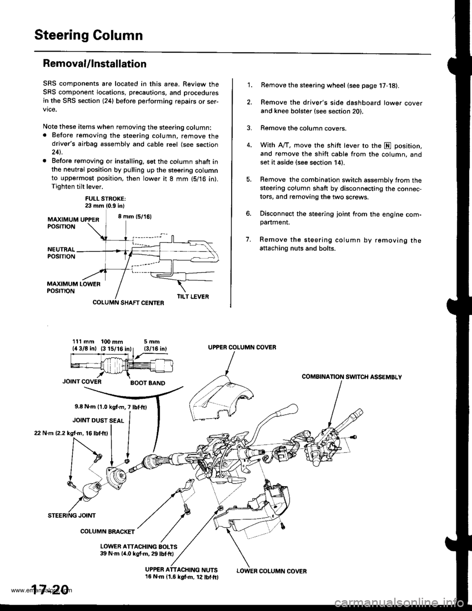
Steering Column
Removal/lnstallation
SRS components are located in this area. Review the
SRS component locations, precautions, and procedures
in the SRS section (24) before performing repairs or ser-
vice.
Note these items when removing the steering column:. Before removing the steering column, remove thedriver's airbag assembly and cable reel (see section24).
. Before removing or installing, set the column shaft inthe neutral position by pulling up the steering columnto uppermost position, then lower it 8 mm (5/16 in).Tighten tilt lever.
FULL STROKE:23 mm 10.9 in)
MAXIMUM UPPER8 mm (5/16)
POSTTTON
Remove the steering wheel (see page 17-18).
Remove the driver's side dashboard lower cover
and knee bolster (see section 20),
Remove the column covers.
With A"/T, move the shift lever to the E position,
and remove the shift cable from the column. andset it aside (see section 14).
Remove the combination switch assembly from thesteering column shaft by disconnecting the connec-
tors, and removing the two screws.
Disconnect the steering joint from the engine com-panment.
Remove the steering column by removing theattaching nuts and bolts.
7.
1.
MAXIMUM LOWERPOSTTTON
SHAFT CENTER
111 mm 100 mm5mm
JOINT COVERBOOT BAND
9,8 N.m l r .0 kgf.m, 7 lbf.fO
JOINT DUST SEAL
22 N.m (2.2 kgl.m, 16lbtftl
TILT LEVER
UPPER ATTACHING NUTS16 N.m lr.6 kgf.m, 12 lbf.ftl
UPPER COLUMN COVER
COMAINANON SWITCH ASSEMBLY
JOINT
COLUMN BMCKET
LOWER ATTACHING BOLTS39 N.m lir,o kgf.m, 29 lbf.ft)
17-20
LOWER COLUMN COVER
www.emanualpro.com
Page 982 of 1395
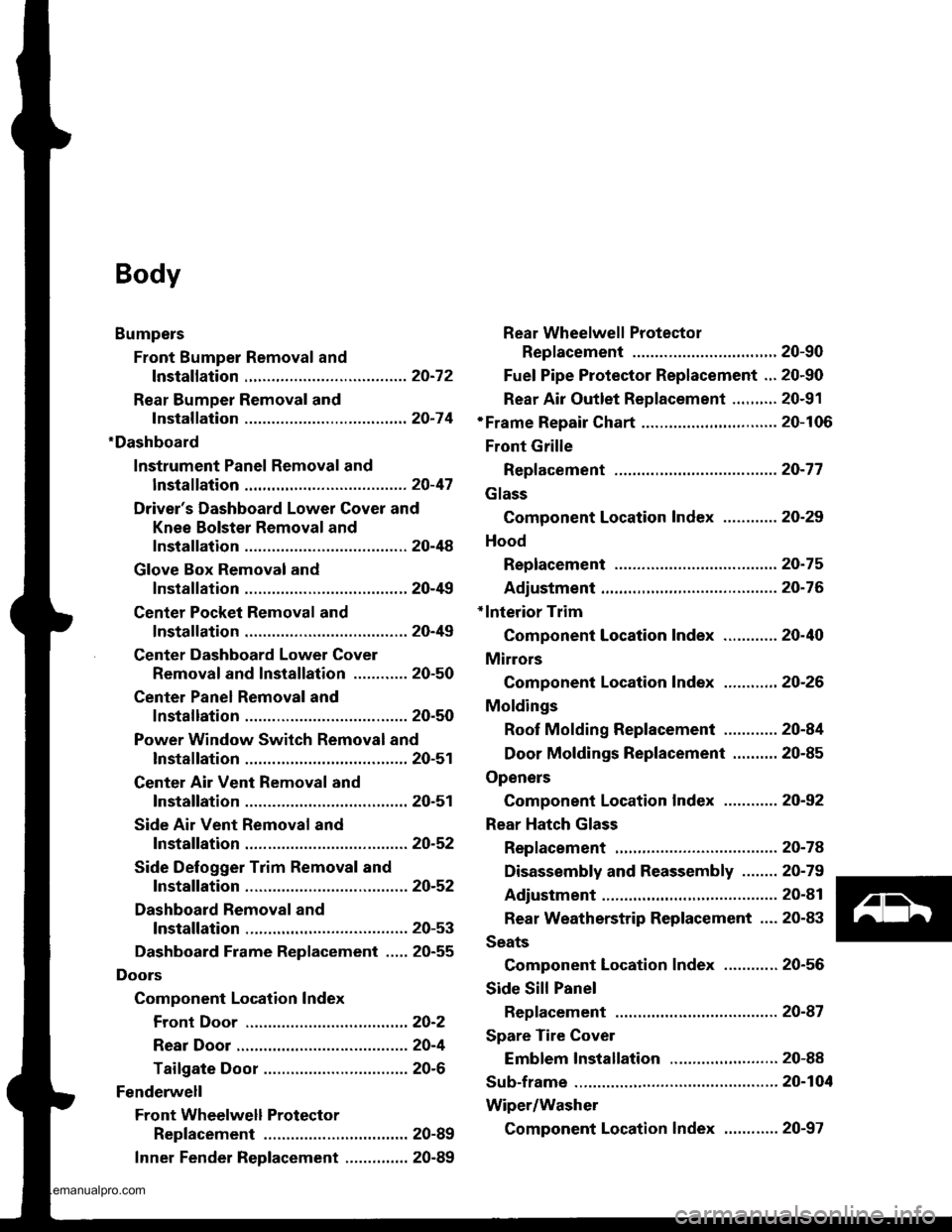
Body
Bumpers
Front Bumper Removal and
fnstaflation .........20-72
Rear Bumper Removal and
fnstaflation .........20-74
'Dashboard
lnstrument Panel Removal and
lnstallation .........20-47
Driver's Dashboard Lower Cover and
Knee Bolster Removal and
Installation .........20-48
Glove Box Removal and
lnstallation .........20-49
Center Pocket Removal and
lnstallation .........20-49
Center Dashboard Lower Cover
Removal and lnstallation ............ 20-50
Center Panel Removal and
lnstallation .........20-50
Power Window Switch Removal and
lnstallation .........20-51
Center Air Vent Removal and
lnstallation .........20-51
Side Air Vent Removal and
fnstallation .........20-52
Side Defogger Trim Removal and
fnstallation .........20-52
Dashboard Removal and
lnstallation .........20-53
Dashboard Frame Replacement ..... 20-55
Doors
Component Location Index
Front Door ,,...,,,,20-2
Rear Door ...........20-4
Tailgate Door ................................ 20-6
Fenderwell
Front Wheelwell Protector
Replacement .....20-89
Inner Fender Replacement .,.....,.,.... 20-89
Rear Wheelwell Protectol
Replacement .....20-90
Fuel Pipe Protector Replacement ... 20-90
Rear Air Outlet Replacement .......... 20-91
*Frame Repair Chart .............................. 20-106
Front Grille
Repf acement .........20-77
Glass
Component Location Index ............ 20-29
Hood
Replacement ......,,,20-75
Adjustment ............20-76
*lnterior Trim
Component Location Index ............ 20-40
Mirrors
Component Location Index .........,,, 20-26
Moldings
Roof Molding Replacement ............ 20-84
Door Moldings Replacement .......... 20-85
Openers
Component Location Index ............ 20-92
Rear Hatch Glass
Replacement .........20-74
Disassembly and Reassembly ........ 20-79
Adiustment ............20-81
Rear Weatherstrip Replacement .... 20-83
Seats
Component Location Index ............ 20-56
Side Sill Panel
Repfacement .........20-87
Spare Tire Cover
Emblem Installation ........................ 20-88
Sub-frame ..................20-104
Wiper/Washer
Component Location lndex ,,,,,....... 20-97
www.emanualpro.com
Page 1184 of 1395
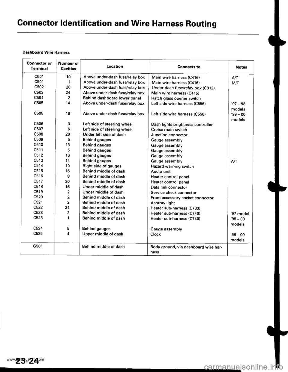
Connector ldentification and Wire Harness Routing
Dashboard Wire Harness
Connector ol
Terminal
Numb€r of
CavitiesLocationConngcts toNotes
c501
c501
c502
c503
c504
c505
c506
c507
c508
c509
c510
c511
c512
c514
c518
c519
c520
c521
c524
10
1
20
14
16
6
20
13
5
t6
14
10
to
20
16
2
24
2
1
5
Above under-dash fuse/relay box
Above under-dash fuse/relay box
Above under-dash fusehelay box
Above under-dash fuse/relay box
Behind dashboard lower panel
Above under-dash fuse/relay box
Above under-dash fuse/relay box
Left side of steering wheel
Left side of steering wheel
Under left side of dash
Behind gauges
Behind gauges
Behind gauges
Behind gauges
Behind gauges
Right side of gauges
Behind middle of dash
Behind middle of dash
Behind middle of dash
Under middle of dash
Under middle of dash
Behind middle of dash
Behind middle of dash
Behind middle of dash
Behind middle of dash
Behind middle of dash
Behind gauges
Upper middle of dash
Main wire harness (C416)
Main wire harness (C416)
Under-dash fuse/relay box 1C912)
Main wire harness (C415)
Hatch glass opener switch
Left side wire harness (C556)
Left side wire harness (C556)
Dash lights brightness cont.oller
Cruise main switch
Junction connector
Gauge assembly
Gauge assembly
Gauge assembly
Gauge assembly
Gauge assembly
Hazard warning switch
Audio unit
Heater control panel
Heater control panel
Data link connector
Service check connector
Front accessory socket connector
Ashtray light
Heater sub-harness (C733)
Heater sub-harness {C740}
Heater sub-harness (C740)
Gauge assembly
Clock
'97 - 98
models'99 - 00
models
Mir
A/r
'97 model'98 - 00
mooets
'98 - 00
models
G501Behind middle of dashBody ground, via dashboard wire har-
ness
23-24
www.emanualpro.com
Page 1313 of 1395
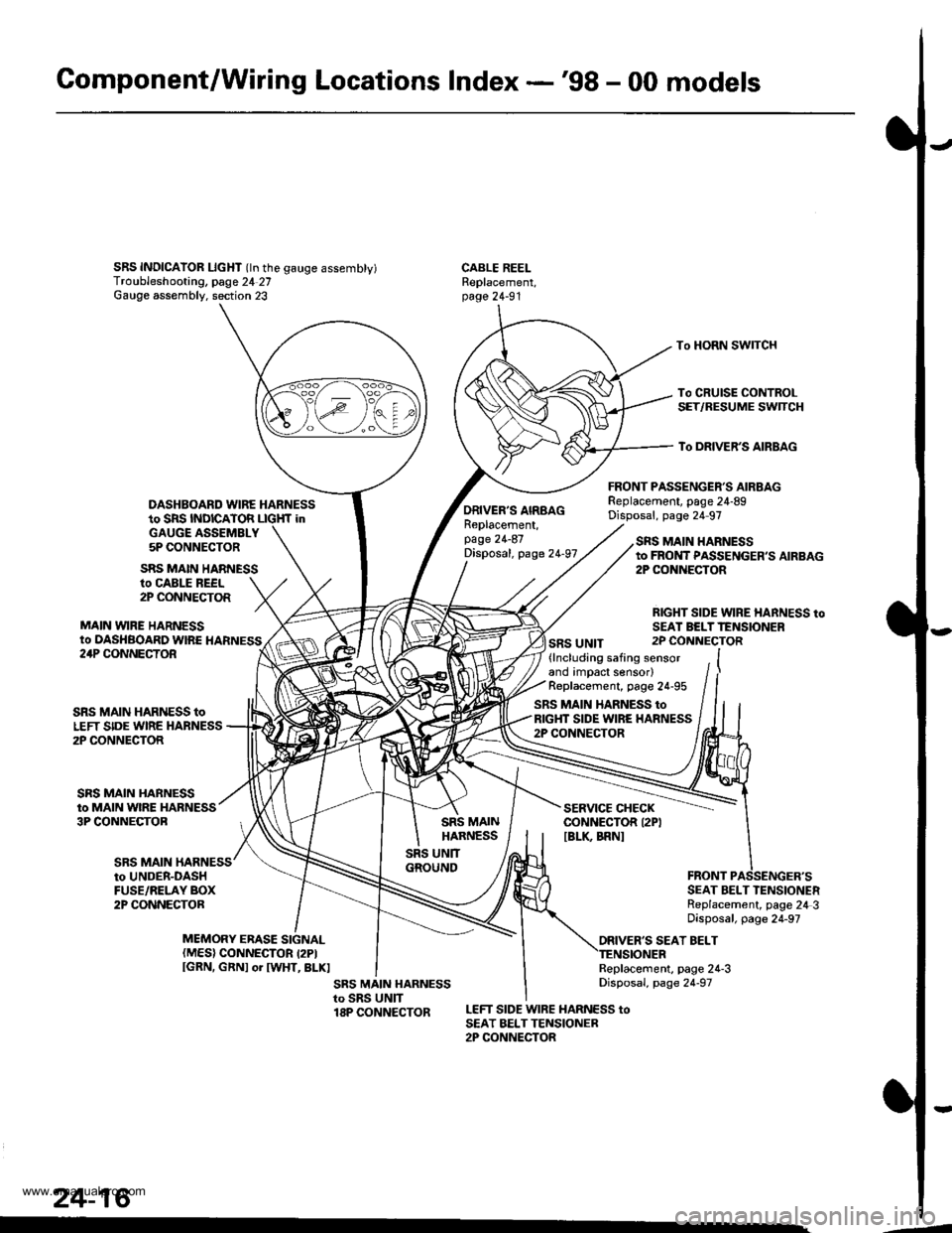
Gomponent/Wiring Locations Index -'98 - 00 models
SRS INDICAIOR LIcHT (ln the gauge assembty)Troubleshooting, page 24 27Gauge assembly. section 23
DASHBOARD WIRE HARNESSto SRS INDICATOR LIGHf inGAUGE ASSEMBLY5P CONNECTOR
FRONT PASSENGER'S AIRBAGReplacement, page 24-89Disposal, page 24 97
CABLE REELReplacement,page 24-91
To HORN SWITCH
To CRUISE CONTROLSET/RESUME SWTCH
To DRIVER'S AIRBAG
ro CABLE REEL2P CONNECTOR
MAIN VYIRE HARNESSto DASHBOARD WIRE HARNESS
SRS MAIN HARNESS
ORIVER'S AIRBAGReplacement,page 24-87Disposal, page 24-97
SRS UNIT
SRS MAIN HARNESSto FROI{T PASSENGER,S AIRBAG2P CONiIECTOR
RIGHT SIDE WIRE HARNESS toSEAI BELTTENSIONER2P CONNECTOR24P CONNECTOR
SRS MAIN
SRS MAIN HARNESS toLEFT SIDE WIRE HARNESS2P CONNECTOR
SRS MAIN HARNESSto MAIN WIRE HARNESS3P CONNECTOB
(lncluding safing sensorand impact sensor)Replacement, page 24-95
SRS MAIN HARNESS toRIGHT SIDE WIRE HARNESS2P CONNECTOR
SERVICE CHECKCONNECTOR I2PIIBLK BRNI
to UNDER-DASHFUSE/RELAY BOX2P CONNECTORSEAT BELT TENSIONERReplacement, page 24 3Disposal, page 24-97
ORIVER'S SEAT BELTMEMORY ERASE SIGNAL(MES) CONNECTOR I2PIIGRN, GRNI or IWHT, BLKIReplacement, page 24-3Disposal, page 24-97
LEFT SIDE WIRE HARNESS toSEAT BELTTENSIONER2P CONNECTOR
24-16
.4
www.emanualpro.com
Page 1330 of 1395
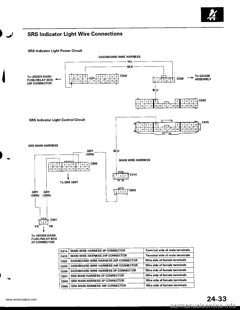
SRS Indicator Light Wire Connections
SRS Indicator Light Power Circuit
DASHBOARD WIRE HARNESS
YEL
BLK
To UNDER-DASHFUSE/RELAY BOX <_
20P CONNECTOR
To GAUGEcsog + assEMBLy
SRS Indicator Light Control Circuit
SRS MAIN HARNESS
)-MAIN WIRE HARNESS
VAIVBIt
To UNDER-DASHFUSE/BELAY BOX2P CONNECTOR
c414MAIN WIRE HARNESS 3P CONNECTORTerminal side of msle t€rminals
c415MAIN wlRE HARNESS 24P CONNECTORTerminal aide of male terminals
c502DASHBOARD WIRE HARNESS 2OP CONNECTORWire side of lemslo terminsls
c503OASHBOARD WIRE HARNESS 24P CONNECTORWire side of female t€rminal3
c509DASHBOABD WIRE HARNESS 5P CONNECTORWire sid€ ot lemale te.minals
c801SRS MAIN HARNESS 2P CONNECTORwire side ol f.male terminals
c803SRS MAIN HARNESS 3P CONNECTORWire side ol female terminals
c806SRS MAIN HARNESS T8P CONNECTORWire side of lomrle terminals
)
24-33
www.emanualpro.com