Middle HONDA CR-V 1999 RD1-RD3 / 1.G Workshop Manual
[x] Cancel search | Manufacturer: HONDA, Model Year: 1999, Model line: CR-V, Model: HONDA CR-V 1999 RD1-RD3 / 1.GPages: 1395, PDF Size: 35.62 MB
Page 22 of 1395
Lift and Support Points
1.
Floor Jack
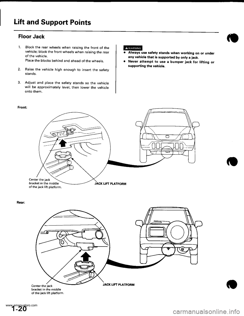
Block the rear wheels when raising the front of thevehicle; block the front wheels when raising the rearof the vehicle.
Place the blocks behind and ahead of the wheels,
Raise the vehicle high enough to insert the safetystanos.
Adjust and place the safety stands so the vehiclewill be approximately level, then lower the vehicleonto them.
Front:
Center the jack
bracket in the middleof the jack lift platform.
Always usg safety standg when working on or underany vehicle that is supported by only a iack.Nevor attempt to use a bumper jack for tifting orsupporting ths vehicl€.
Rsar:
JACK LIFT PLATFORM
Center the iackbracket in the middleof the iack lift platform.
1-20
JACK LIFT PLATFORM
www.emanualpro.com
Page 31 of 1395
Standards and Service Limits
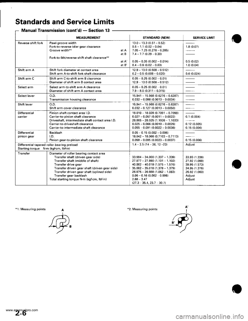
Manual Transmission {cont'd} - Section 13
11: fuleasuring points A
A
'Ay"
-l-...
_{-P)
A'*2: Measuring points
MEASUREMENTSTANDARO INEW) SERVICE LIMIT
Raverse shift IorkPawl groove widthFork-to-reverse idler gear clearanceGroove width*l at AatBFork-to-5th/reverse shift shaft clearance*'�
at B'
'13.0 - 13.3 (0.5'�j - 0.52)0.5 - 1.1 (0.02 - 0.04)7.O5 - 7.25 i.0.21 4 - 0.24517.4 -7.7 t0.29 0.301
0.05 - 0.35 (0.002 - 0.014)0.4,0.8 (0.02 0.03)
18 (0.07)
0.5 {0.02)1.0 (0.04)
Shift arm AShift fork diameter at contact areaShift arm A-to-shitt tork shaft clearance12.9 - 13.0 (0.508 - 0.512)0.2 - 0.5 (0.008- 0.020)0.6 {0.024i
Shift arm CShift arm C'to-shift arm B clearanceDiameter of shift arm B contact area0.05 0.25 (0.002 0.01)r2.9 - 13.0 (0.508 - 0.512)
Select armSelect arm'to-shift arm A clearanceDiameter of shift arm A contact area0.05 - 0.25 (0.002 0.01)7.9 - 8.0 (0.311 - 0.31s)
Select levero.D.Transmission housing clearance15.94r - 15.968 (0.6276 - 0.6287)0.032 - 0.086 (0.0013 - 0.0034)
Shift levero.D.Sh ift arm cover clearancer5.941 - 15.968 (0.6276 - 0.6287)0.032 - 0.127 (0.0013 - 0.0050)
DifferentialcarnerPinion shaft contact area LD.Carrier-to-pinion shaft clearanceDriveshaft, intermediate shatt contact area LD,Carrier-to-driveshaft clearanceCarrierto-interrnediate shaft clearance
18.010 18.028 (0.7091 - 0.7098)0.027 - 0.057 (0.0011 - 0.0022)28.005 - 28.025 (1.1026, 1.1033)0.025 - 0.066 (0.0010,0.0026)
0.055 - 0.091 10.0022 - 0.0036)
0.1 (0.004)
0.12 {0.005i0.15 (0.006i
Differentialpinion gearBacklasht.D.Pinion gearto-pinion shaft clearance
0.05-0.r5 {0.002 - 0.006)18.042 - 18.066 (0.7103 - 0.7113)0.059 - 0.095 10.0023 - 0.0037)oru ro.ooor
Ditferential tapered roll€r besring preloacStaning torque N.m (kgf.cm, lbl.ini
1.4 2.5i'14 26,12 -231Adjust
TransterDiameter of roller bearing contact areaTransler shaft {driven gear side}Translor shaft {middle of shaft)Transter drive gearTranslor driven gear shaft {driven gear side)Transter driven gear shaft (splined side)Trans{er gear backlashTotalstarting torque N.m (kgicm, lbiin)
33.984 - 34.000 (1.337 - 1.339)21.977 - 27.99011.101 1.102140.002 - 40.01811.575 - 1.576)35.002 - 35.01811.378 - 1.379)26.975, 26.988 (1.062 1.063)0.06 - 0.16 {0.002 0.006)2.64 3.41\21.3,35.4,23.1 30.t|
33.93 (1.336)
27 .92 (1 .O99)39.95 (1.573)
34.95 (1.376)
26.92 (1.060)
AdjustAdjust
2-6
www.emanualpro.com
Page 34 of 1395
2-9
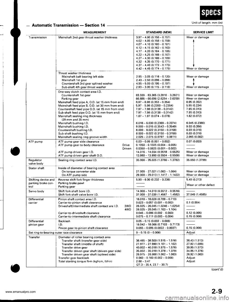
Automatic Transmission - Section 14
o
Unit of length: mm (in)
o
MEASUREMENTSTANDARD (NEWISERVICE LIMIT
TransmissionMainshaft 2nd gear thrust washer thickness3.97 - 4.00 10.156 - 0.157)4.02 - 4.05 {0.158 - 0.159)4.07 - 4.1010.160 0.161)4.12 - 4.15 (0.162 - 0.163)4.17 4.20 (0.164 0.165)4.22 - 4.25 10.166 - 0.167 )4.27 - 4.30 (0.168 - 0.169)4.32 4.35 (0.170-0.171)
4.37 - 4.40 (0.172 0.173)4.42 - 4.45 (0.174 - 0. r75)
I
I
IWear or damage
Thrust washer thicknessl'rainshaft ball bearing left sideMainshaft 1st gear
Countershaft 3rd gear splined washerSub-shaft 4th gear thrust washer
2.95 3.05 (0.116 0.120)2.43 - 2.50 (0.096 - 0.098)4.9s - 5.00 (0.195 - 0.197)2.93 - 3.00 (0.115 - 0.1181
Wear or damage
tIWear or damage
One-way clutch contact area LD.Countershaft 1st gearParking gearMainshaft feed pipe A, O.D. (at 15 mm trom end)Mainshaft feed pipe B, O.D. (at 30 mm from end)Countershaft teed pipe O.D. lat 15 mm from end)Sub-shaft feed pipe O.D. (at 15 mm from end)Mainshatt sealing ring thickness(29 mm and 35 mm)Mainshaft bushing I.D.Mainshaft bushing l.D.Countershaft bushing l.D.Sub shatt bushing LD.Mainshaft sealing ring groove width
83.339 83.365 (3.2810 3.2821)66.685 - 66.698 (2.6254 - 2.6259)8.97 - 8.98 (0.353 - 0.354)5.97 5.98 {0.2350 - 0.2354)7.97 - 7.98 (0.3138 - 0.3142)7.97 ,7.98 (0.3138 - 0.3142)1.87 - 1.97 (0.074-0.078)
6.018 - 6.030 (0.2369 - 0.2374)9.000 - 9.015 (0.3543 - 0.3549)8.000 - 8.022 (0.3150-0.3158)
8.000 - 8.022 (0.3150 0.3158)2.025 - 2.075 (0.0797 0.0811)
Wear or damageWear or damage8.95 (0.352)
5.95 (0.234)
7.95 (0.313)
7.95 {0.313)1 .42 $.O72)
5.045 (0.2380)
9.03 (0.356)
8.03 (0.316)
8.03 (0.316)
2.095 (0.082)
ATF pumpATF pump gear side clearanceATF pump gear'to body clearance DriveDrivenATF pump driven gear LD.ATF pump driven gear shaft O.D.
0.03 - 0.05 (0.001 - 0.002)0.1050 0.1325 (0.004, 0.005)0.0350 - 0.0625 10.001 - 0.002)14.016* 14.034 (0.5518 0.5525)13.980 - 13.990 {0.5504 0.5508)
0.0710.003)
Wear or damageWear or damage
Regulatorvalve bodySealing ring contact area l.D,35.000 35.025 {1.3780 - 1.3782)35.050 (1.3799)
Stator shaftInside of diameter oI bearing contact areaOn torque convener sideOn ATF pump side2't .o00 27 .021 I '1 .063 , 1 .064)29.000 - 29.01311.r417 1.1422)Wear or damageWear or damage
Shifting device andparking brake con'trol
Reverse shitt fork finger thicknessParking brake pawl
Parking gear
5.90 - 6.00 {0.232,0.236)5.40 (0.213)
lWear or other defect
Servo bodyShift fork shatt bore l.D.Shift fork shatt valve bore l.D.14.000 - 14.010 (0.55'�l2 - 0.5516)37.000 - 37.039 (1.4567 - 1.4582)37.045 (1.4585)
DifferentialcarrierPinion shaft contact area LD.Carrierto-pinion shaft clearanceDriveshafvintermediate shaft contact are l.D. 2WD4WDCarrier to driveshalt clearanceCarrier-to-intermediate shaft clearance
'18.010 - 18.028 10.709 - 0.710)0.023 - 0.057 {0.001 - 0.002}26.025 - 26.045 (1.0246 - 1.0254)28.025 - 28.045 (1.103 - 1.104)0.045 - 0.08610.002 0.003)0.075 - 0.111 10.003- 0.004)
0.r {0.004)
0.12 (0.005)
0.15 (0.006)
Differentialprnron gearBacklasht.D.Pinion gear'to-pinion shaft clearance
0.05 - 0.15 (0.002 - 0.006)18.062 - 18.066 (0.7103 - 0.7113)0.055 - 0.095 10.0022 - 0.0037)otu to.oout
Set ring-to-bearing outer race clearance0 0.15 (0 - 0.006)Adjust
TransferDiameter of roller bearing contact areaTransfer shaft (transfer gear side)Transfer shaft (middle of shaft)Transfer drive gearTransfer driven gear shaft {driven gear side)Transfer driven gear shaft {splined side)Transfer gear backlashTotalstarting torque N.m (kgf.cm, lbf.in)
38.485 38.500 (1.515 - 1.516)27 .917 - 21 .990 |.1.101 - 1.102)40.002 - 40.018 (1.575 - 1.576)35.002 35.018 (1.378 - 1.379)26.975 26.988 (1.062 -'�l.063)
0.060 0.160 (0.002 - 0.006)2.64 - 3.41127.3 - 35.4,23.1 30.71
38.43 (1.513)
27.92 (1.099)
39.95 (1.573)
34.95 (1.376)
26.92 (1.060)
AdiustAdiust
(cont'd)
www.emanualpro.com
Page 116 of 1395
Valve Clearance
Adiustment
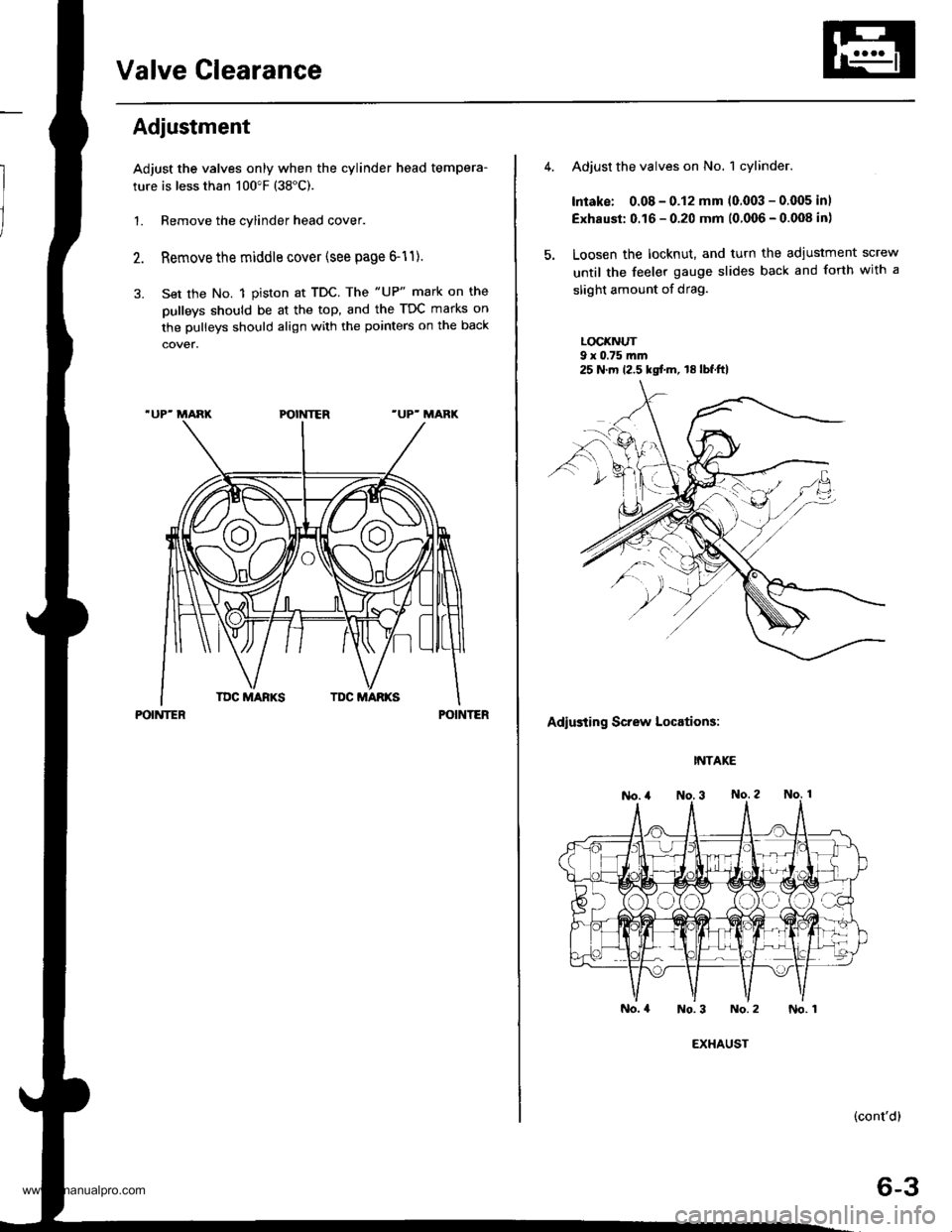
Adjust the valves only when the cylinder head tempera-
ture is less than 100"F (38"C).
1. Remove the cylinder head cover.
Remove the middle cover (see page 6-11).
Set the No. 1 piston at TDC. The "UP" mark on the
pulleys should be at the top, and the TDC marks on
the pulleys should align with the pointers on the back
POINTERPOINTER
Adjust the valves on No. 1 cylinder.
Intake: 0.08 - 0.12 mm (0.003 - 0.005 inl
Exhaust: 0.16 - 0.20 mm (0.006 - 0.008 in)
Loosen the locknut, and turn the adiustment screw
until the feeler gauge slides back and forth with a
slight amount of drag.
LOCI(NUT9 x 0.75 m.n
Adiusting Screw Locations:
INTAKE
No.4 No.3 No.2
(cont'd)
6-3
25 N.m 12.5 kgf.m, 18lbf.ft)
EXHAUST
No. 1
www.emanualpro.com
Page 124 of 1395
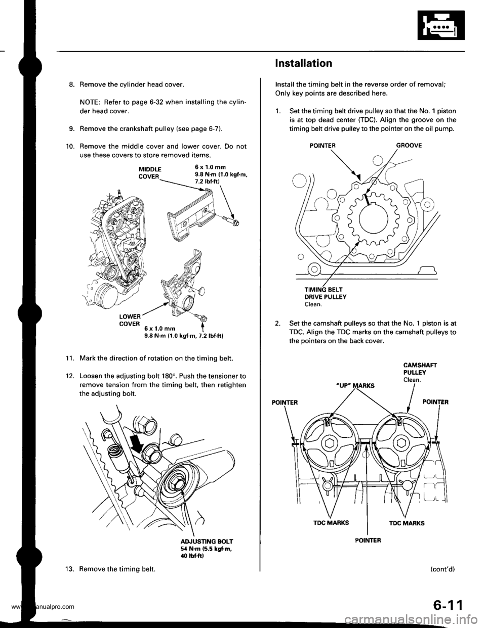
8. Remove the cylinder head cover.
NOTE: Refer to page 6-32 when installing the cylin-
der head cover.
Remove the crankshaft pulley (see page 6-7).
Remove the middle cover and lower cover. Do not
use these covers to store removed items.
9.
10.
11.
MTDDLE 6x1.0mm
COVER 9.8 N.m {1.0 kgt m,
LOWERCOVER
9.8 N.m (1.0 kgt.m, 7.2 lbf.ftl
Mark the direction of rotation on the timing belt.
Loosen the adjusting bolt 180'. Push the tensioner to
remove tension from the timing belt, then retighten
the adiusting bolt.
AINUSTING BOLT54 N.m (5,5 kgt m,.(} tbf.rrl
12.
13. Remove the timing belt.
Installation
Install the timing belt in the reverse order of removal;
Only key points are described here,
1. Set the timing belt drive pulley so that the No. 1 piston
is at top dead center (TDC). Align the groove on the
timing belt drive pulley to the pointer on the oil pump.
GROOVE
DRIVE PULLEYClean.
2. Set the camshaft pulleys so that the No. I piston is at
TDC. Align the TDC marks on the camshaft pulleys to
the pointers on the back cover.
POINTER
CAMSHAFTPULLEYClean.
POINTER
r-t
(cont'd)
6-11
www.emanualpro.com
Page 125 of 1395
Timing Belt
Installation (cont'd)
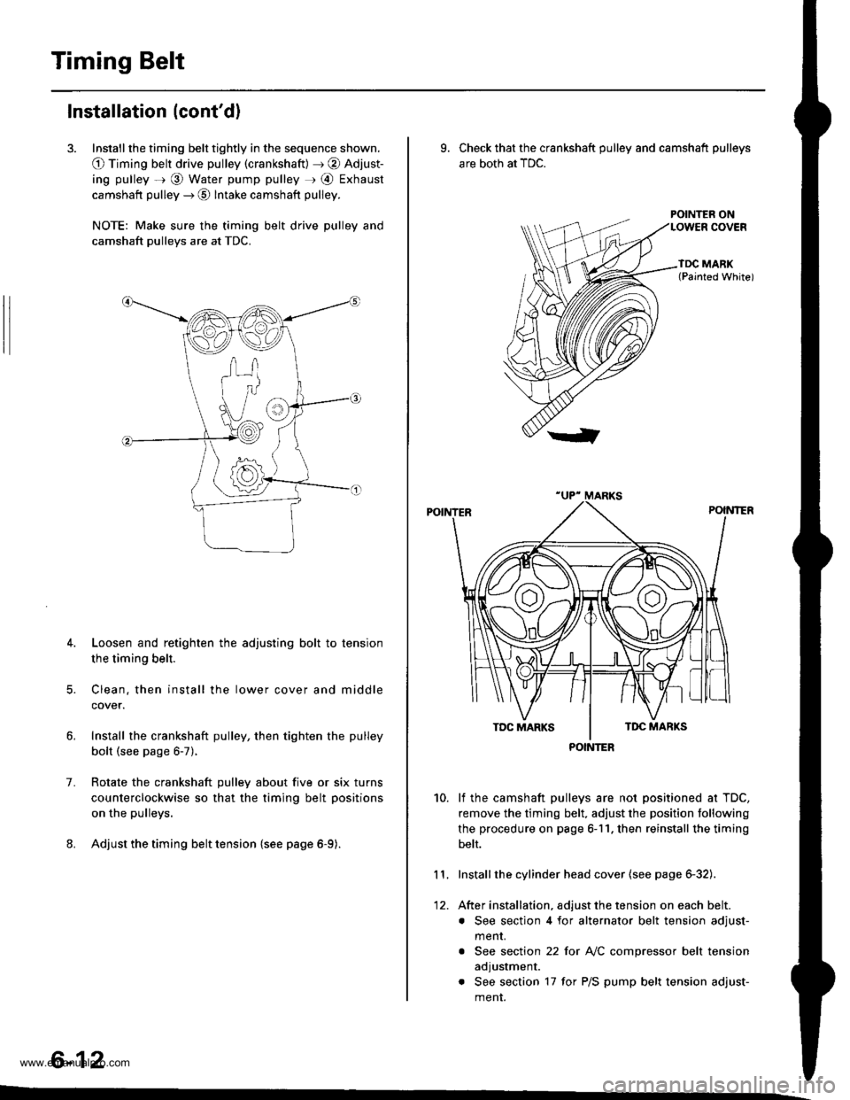
3. Install the timing belt tightly in the sequence shown.
O Timing belt drive pulley (crankshaft) J @ Adjust-
ing pulley =r @ Water pump pulley r @ Exhaust
camshaft pulley --) @ Intake camshaft pulley.
NOTE: Make sure the timing belt drive pulley and
camshaft pulleys are at TDC.
4. Loosen and retighten the adjusting bolt to tension
the timing belt.
5. Clean. then install the lower cover and middle
cover.
Install the crankshaft pulley, then tighten the pulley
bolt (see page 6-7).
Rotate the crankshaft pulley about five or six turns
counterclockwise so that the timing belt positions
on the pulleys.
Adjust the timing belt tension {see page 6-9).
1.
6-12
9. Check that the crankshaft pulley and camshaft pulleys
are both at TDC.
POINTER ON
lf the camshaft pulleys are not positioned at TDC,
remove the timing belt. adjust the position following
the procedure on page 6-11. then reinstall the timing
belt.
Installthe cylinder head cover (see page 6-32).
After installation, adjust the tension on each belt.
. See section 4 for alternator belt tension adjust-
menr.
. See section 22 for NC compressor belt tension
adjustment.
. See section 17 for P/S pump belt tension adjust-
ment.
10.
11.
12.
POINTER
www.emanualpro.com
Page 126 of 1395
CKF Sensor
Replacement
1.
|o|'ln PUUCY BMCKET SOLIl0 r 1.25 mm14 .m 14.5 kgl.m,3:' lbtftl
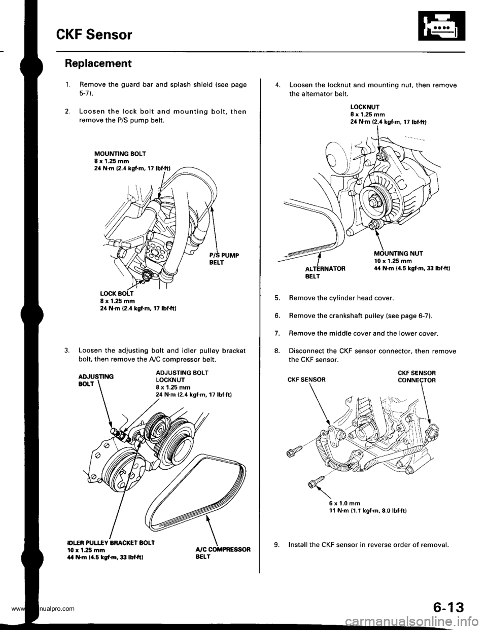
Remove the guard bar and splash shield (see page
5-7 t.
Loosen the lock bolt and mounting bolt, then
remove the P/S pump belt.
MOUNTING BOLT8 x 1.25 mm
PUMPBELT
Loosen the adjusting bolt and idler pulley bracket
bolt, then remove the Ay'C comDressor belt.
ADJUSTING BOLTLOCKNUT8 x 1.25 mm24 N.m {2.4 kgf.m, 17 lbf.ft)
24 N.m (2.{ kgf.m, 17 lbf.ttl
24 N.m 12.4 lgf.m, 17 lbl.ftl
4. Loosen the locknut and mounting nut, then remove
the alternator belt.
LOCKNUT8 x 1.25 mm24 N.m (2.4 kgl.m, 17 lbtftl
10 x 1 .25 mma4 N.m (4.5 kgt m, 33 lbtft)
E
6.
7.
aJ.
Remove the cylinder head cover.
Remove the crankshaft pulley (see page 6-7).
Remove the middle cover and the lower cover.
Disconnect the CKF sensor connector, then remove
the CKF sensor.
6x1.0mm11 N.m {1.r kgnm,8.0 lbfft)
9. Install the CKF sensor in reverse order of removal.
BELT
CKF SENSOR
6-13
www.emanualpro.com
Page 157 of 1395
Crankshaft
Inspection
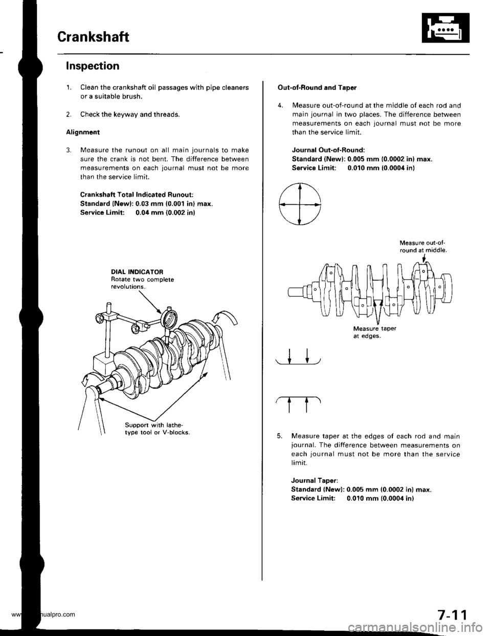
1. Clean the crankshaft oil passages with pipe cleaners
or a suitable brush.
2. Check the keyway and threads.
Alignment
3. Measure the runout on all main journals to make
sure the crank is not bent. The difference between
measurements on each journal must not be more
than the service limit.
Crankshaft Total Indicated Runout:
Standard lNew):0.03 mm (0.001 in) max.
Service Limit: 0.04 mm {0.002 in)
DIAL INDICATORRotate two completerevolut|ons.
Suppon with lathe-lype tool or V-blocks.
Out-of-Round and TaDer
4. Measure out-of-round at the middle of each rod and
main journal in two places. The difference between
measurements on each lournal must not be more
than the service limit.
Journal Out-of-Round:
Standard (Newl:0.005 mm 10.0002 inl max.
Service Limit: 0.010 mm (0.000i1in)
Measure out-ol'round at middle.
Measure taperat edges.
5. Measure taper at the edges of each rod and mainjournal. The difference between measurements on
each iournal must not be more than the service
limit.
Journal Taperi
Standard {Newl: 0.005 mm 10.0002 inl max.
Service Limit: 0.010 mm (0.0004 inl
7-11
www.emanualpro.com
Page 175 of 1395
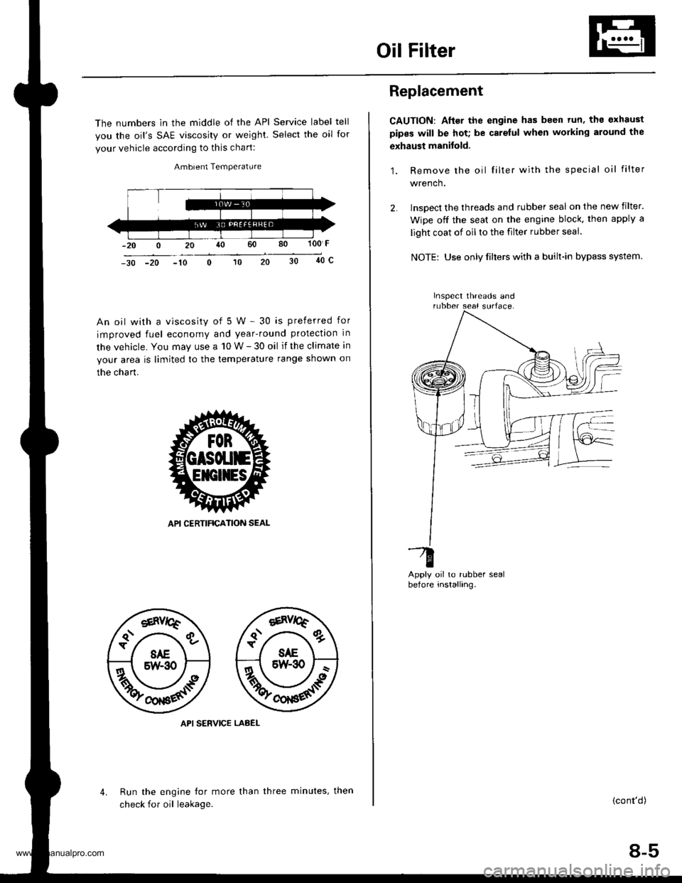
Oil Filter
The numbers in the middle of the API Service label tell
you the oil's SAE viscosity or weighl. Select the oil for
your vehicle according to this chart:
Ambient Temperature
100 F
40c-30 -20 -10
An oil with a viscosity of 5 W - 30 is preferred for
improved fuel economy and year-round protection in
the vehicle. You may use a 10 W - 30 oil if the climate in
your area is limited to the temperature range shown on
the chart.
API SERVICE LABEL
Run the engine tor more than
check for oil leakage.
4.three minutes, then
Replacement
CAUTION: After the engine has been tun, ths exhaust
pipes will be hot; be carelul when working around the
exhaust manitold.
1. Remove the oil filter with the special oil filter
wrench.
lnsoect the threads and rubber seal on the new filter.
Wipe off the seat on the engine block, then apply a
light coat of oil to the filter rubber seal.
NOTE: Use only filters with a built-in bypass system.
oil to rubber sealinstalling.
-G
Derore
(cont'd)
8-5
Inspect threads and
www.emanualpro.com
Page 179 of 1395
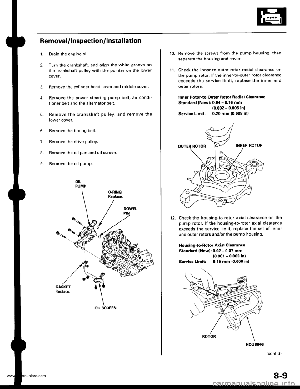
1.
2.
3.
RemovaUlnspection/lnstallation
Drain the engine oil.
Turn the crankshaft, and align the white groove on
the crankshaft pulley with the pointer on the lower
cover.
Remove the cylinder head cover and middle cover.
Remove the power steering pump belt, air condi-
tioner belt and the alternator belt.
Remove the crankshaft pulley, and remove the
lower cover.
6. Remove the timing belt.
7. Remove the drive pulley.
8. Remove the oil pan and oil screen.
9. Remove the oil pump.
orLPUMP
OLRINGReplace.
5.
OIL SCREEN
10.
ll.
Remove the screws from the pump housing, then
separate the housing and cover.
Check the inner-to-outer rotor radial clearance on
the pump rotor. lf the inner-to-outer rotor clearance
exceeds the service limit. replace the inner and
outer rotors.
lnner Rotor-to Outar Rotor Radial Clearance
Standard {Newl: 0.04 - 0.16 mm
{0.002 - 0.006 inl
Service Limit: 0.20 mm (0.008 in)
Check the housing-to-rotor axial clearance on the
pump rotor. lf the housing-to-rotor axial clearance
exceeds the service limit. replace the set of inner
and outer rotors and/or the pump housing.
Housing-to-Rotor Axial Clearance
Standard {New): 0.02 - 0.07 mm
{0.001 - 0.003 in)
So|'�ice Limit: 0.15 mm (0.006 inl
(cont'd)
8-9
HOUSING
www.emanualpro.com