Pulley sensor HONDA CR-V 1999 RD1-RD3 / 1.G Workshop Manual
[x] Cancel search | Manufacturer: HONDA, Model Year: 1999, Model line: CR-V, Model: HONDA CR-V 1999 RD1-RD3 / 1.GPages: 1395, PDF Size: 35.62 MB
Page 114 of 1395

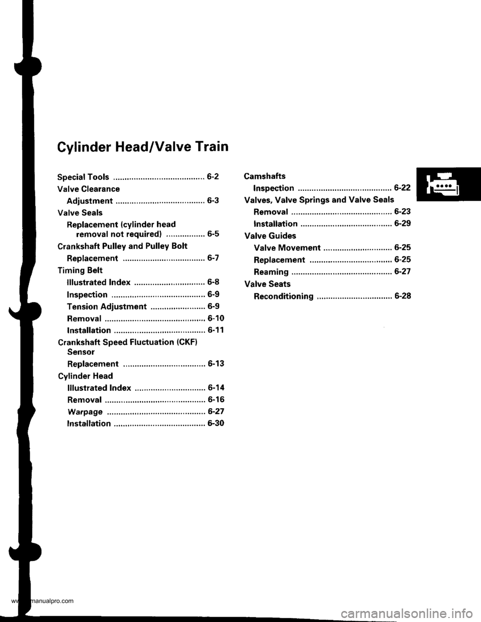
Cylinder Head/Valve Train
Speciaf Tools .............6-2
Valve Clearance
Adiustment ............6-3
Valve Seals
Replacement (cylinder head
removal not requiredl ................. 6-5
Crankshaft Pulley and Pulley Bolt
Replacement .........6-7
Timing Belt
I llustrated lndex ............................... 6-8
Inspection ............., 6-9
Tension Adjustment ........................ 6-9
Removal ...........,..... 6-10
lnstallation .............6-11
Crankshaft Speed Fluctuation (CKFI
Sensor
Replacement .........6-13
Cylinder Head
lllustrated lndex ............................... 6-14
Removal .................6-16
Warpage ................6-27
lnstallation ............. 6-30
Camshafts
lnspection ..............6-22
Valves, Valve Springs and Valve Seals
Removal ................, 6-23
lnstallation ............. 6-29
Valve Guides
Valve Movement ............,,,,.,............ 6-25
Replacement .........6-25
Reaming .................6-27
Valve Seats
Reconditioning ......6-28
www.emanualpro.com
Page 121 of 1395

Timing Belt
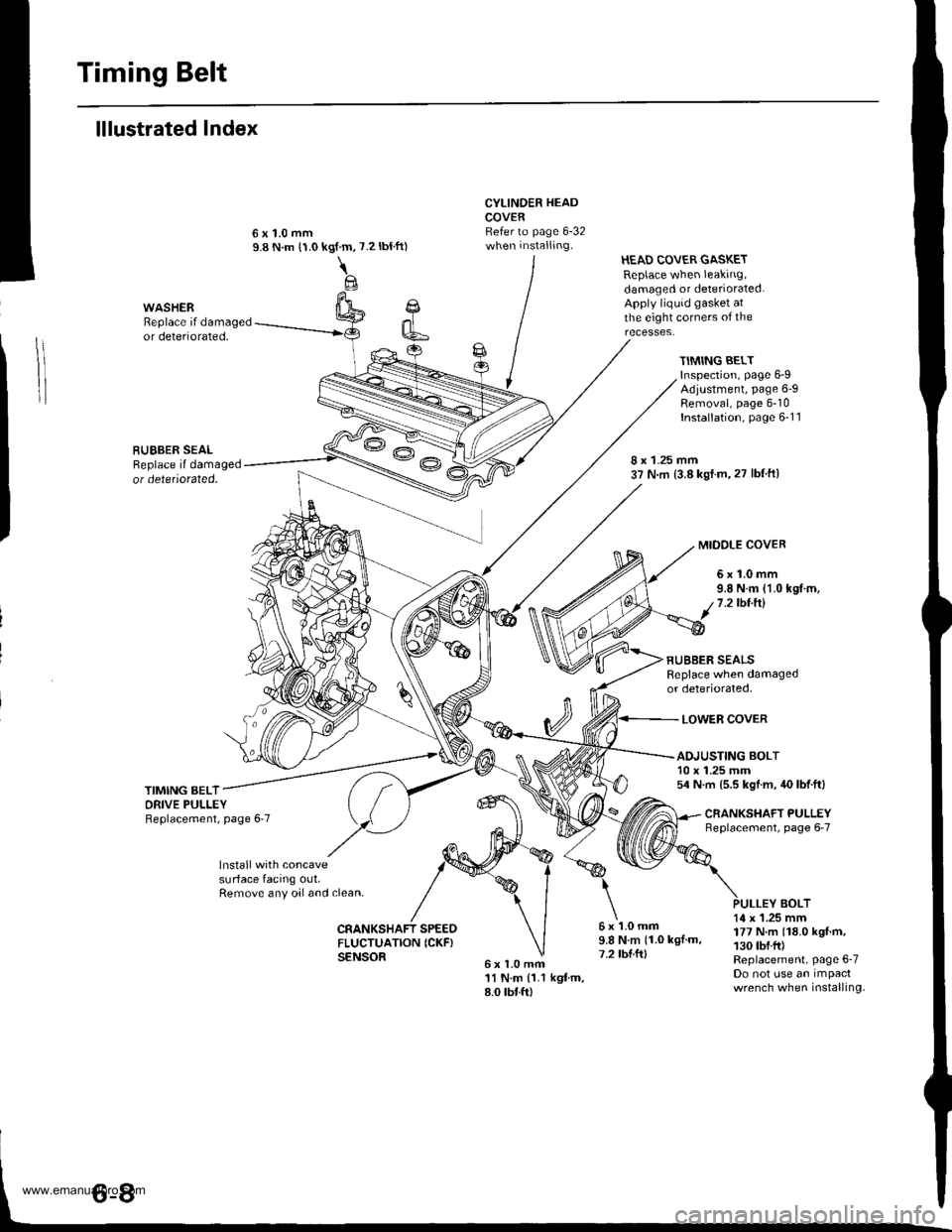
lllustrated Index
Cl
k6
CYLINDER HEADCOVERRefer to page 6-32when installing.
6x1.0mfi11 N.m {1.1 kgtm,8.0 rbtft)
HEAD COVER GASKETReplace when leaking,damaged or deteriorated.Apply liquid gasket atthe eight corners of theWASHERReplace if damagedor deteriorated,
RUEBER SEALReplace il damagedot detetiorated.
kgf.m,
\@
7.2 tbtft)
TIMING BELTInspection, page 6-9Adjustment, page 6-9Removal, page 6-10Installation, page 6-1 1
8 x 1.25 mm37 N.m (3.8 kst.m,27 lbf ftl
MIDOLE COVER
6x1.0mm9.8 N.m {1.0 kgf.m,1.2lbt.ftl
RUBBER SEALSReplace when damagedor deteriorated,
LOWER COVER
TIMING BELTORIVE PULLEYReplacement, page 6'7
ADJUSTING BOLT10 x 1.25 mm54 N.m (5.5 kgl.m, 40 lbf.ft)
CNANKSHAFT PULLEYneplacement, page 6-7
lnstall with concavesurface facing out,Remove any oal and clean,BOLT
CRANKSHAFT SPEEOFLUCTUATION ICKF}SENSOR
6x1.0mm9.8Nm(1.0kgl.m,7.2 tbl.ft)
14 x 1.25 mm177 N.m (18.0 kgf'm,130 tbf.fr)Replacement, Page 6-7Do not use an impactwrench when installing.
www.emanualpro.com
Page 126 of 1395

CKF Sensor
Replacement
1.
|o|'ln PUUCY BMCKET SOLIl0 r 1.25 mm14 .m 14.5 kgl.m,3:' lbtftl
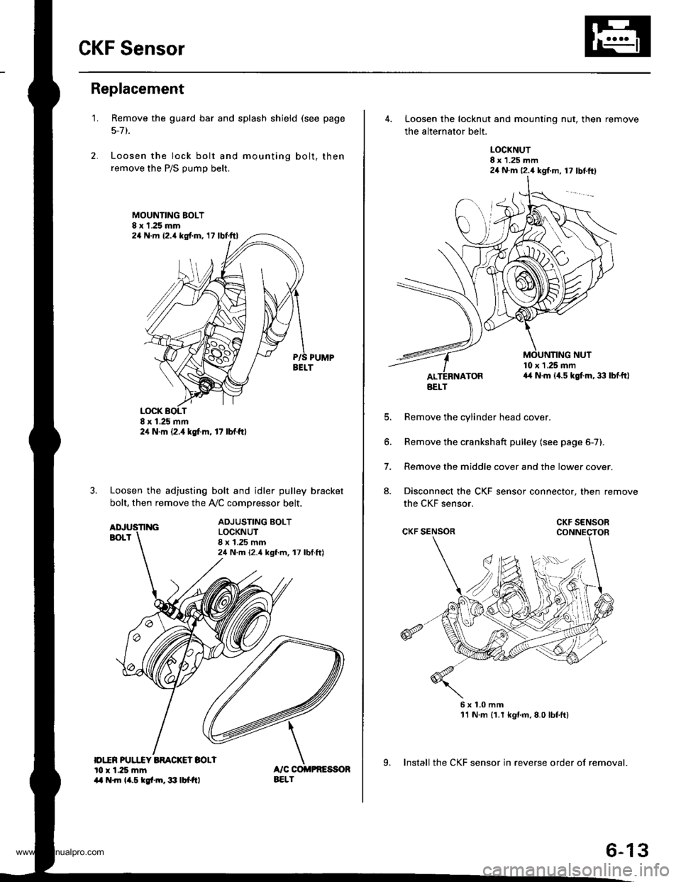
Remove the guard bar and splash shield (see page
5-7 t.
Loosen the lock bolt and mounting bolt, then
remove the P/S pump belt.
MOUNTING BOLT8 x 1.25 mm
PUMPBELT
Loosen the adjusting bolt and idler pulley bracket
bolt, then remove the Ay'C comDressor belt.
ADJUSTING BOLTLOCKNUT8 x 1.25 mm24 N.m {2.4 kgf.m, 17 lbf.ft)
24 N.m (2.{ kgf.m, 17 lbf.ttl
24 N.m 12.4 lgf.m, 17 lbl.ftl
4. Loosen the locknut and mounting nut, then remove
the alternator belt.
LOCKNUT8 x 1.25 mm24 N.m (2.4 kgl.m, 17 lbtftl
10 x 1 .25 mma4 N.m (4.5 kgt m, 33 lbtft)
E
6.
7.
aJ.
Remove the cylinder head cover.
Remove the crankshaft pulley (see page 6-7).
Remove the middle cover and the lower cover.
Disconnect the CKF sensor connector, then remove
the CKF sensor.
6x1.0mm11 N.m {1.r kgnm,8.0 lbfft)
9. Install the CKF sensor in reverse order of removal.
BELT
CKF SENSOR
6-13
www.emanualpro.com