Transmission gasket HONDA CR-V 1999 RD1-RD3 / 1.G Workshop Manual
[x] Cancel search | Manufacturer: HONDA, Model Year: 1999, Model line: CR-V, Model: HONDA CR-V 1999 RD1-RD3 / 1.GPages: 1395, PDF Size: 35.62 MB
Page 103 of 1395
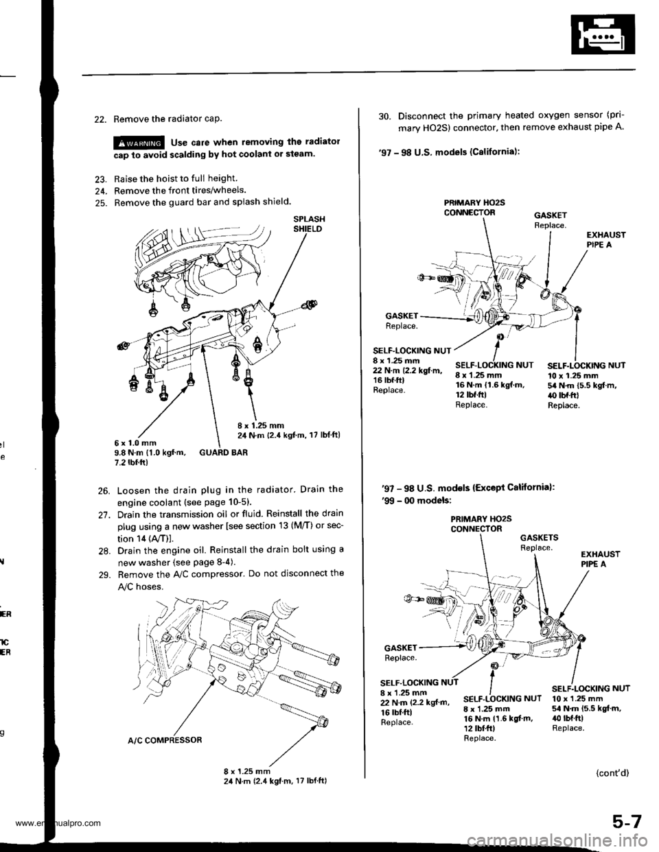
22. Remove the radiator caP.
!@ use care when removing the radiatol
cap to avoid scalding by hot coolani or steam.
23. Raise the hoist to full height
24. Remove the front tires/wheels.
25. Remove the guard bar and splash shield.
8 x 1.25 mm2,1 N.m {2.4 kgf,m, 17 lbl ft)6x1.0mm9.8 N.m {1.0 kgf.m, GUARD BAR7.2 tbf.rr)
Loosen the drain plug in the radiator. Drain the
engine coolant (see page 10-51.
Drain the transmission oil or fluid. Reinstall the drain
plug using a new washer lsee section 13 (M/T) or sec-
tion 14 (ly'T)].
Drain the engine oil. Reinstall the drain bolt using a
new washer {see page 8-4).
Bemove the A,/C compressor. Do not disconnect the
!y'C hoses.
SPLASH
26.
27.
28.
29.
ER
lCEB
30. Disconnect the primary heated oxygen sensor (prl-
mary HO2S) connector. then remove exhaust pipe A
'97 - 98 U.S. models (Cslifornia):
PRIMARY HO2SCONNECTOR
GASKETReplace.
SELF-LOCKING NUT8 x 1.25 mm22 N.m 12.2 kgf.m,16 lbf.ftlReplace.
8 x 1.25 mm16 N.m {1.6 kgf.m.12 tbt.ftlReplace.
SELF.LOCKING NUT10 x 1.25 mm54 N.m 15.5 kgf.m,.() tbf.frlReplace.
NUT
'97 - 98 U.S. mod€ls {Except California):'99 - 00 models:
PRIMARY HO2SCONNECTORGASKETSReplace.
GASKETReplace.
SELF.LOCKING8 x 'l.25 mm22 N.m (2.2 kgf m,
16 rbf.ftlReplace.
SELF.LOCKING NUT
8 x 1.25 mm16 N.m 11.6 kgf.m,12 tbt fr)Replace.
10 x 1.25 mm54 N.m 15.5 kgt.m,40 rbt.ftlReplace.
{cont'd)
5-7
www.emanualpro.com
Page 445 of 1395
Transfer Assembly
lnstallation
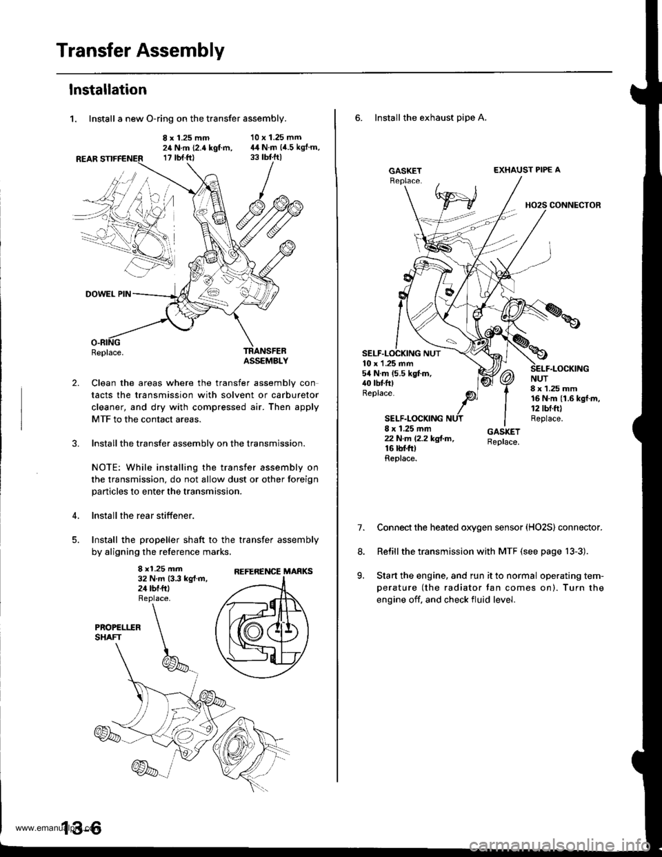
1. Install a new O-ring on the transfer assembly.
8 x 1.25 mm24 N.m (2.4 kgt m,17 rbt.ftl
10 x 1.25 mm44 N.m (4.5 kgJ.m,
2.
DOWEL PIN
Replace.TRANSFEBASSEMBLY
Clean the areas where the transfer assembly con
tacts the transmission with solvent or carburetor
cleaner, and dry with compressed air. Then apply
MTF to the contact areas.
Installthe transfer assembly on the transmission.
NOTE: While installing the transfer assembly on
the transmission, do not allow dust or other foreign
particles to enter the transmission.
lnstall the rear stiffener.
Install the propeller shaft to the transfer assembly
by aligning the reference marks,
8 x1.25 mm32 N.m 13.3 kg{.m,24 tbf.ftl
REFERENCE MARKS
6. Install the exhaust pipe A,
GASKETEXHAUST PIPE A
HO2S CONNECTOR
10 x 1 .25 mm54 N.m (5.5 kgt m,40 tbtfttReplace.
SELF.LOCKING
NUT8 x 1.25 mm16 N.m {1.6 kgf.m,12 tbt.ft)Replace.8 x 1.25 mmzzN.m l2.2kg!-m,16 rbf.trtReplace.
7.Connect the heated oxygen sensor (HO2S) connector.
Relill the transmission with MTF (see page 13-3).
Start the engine, and run it to normal operating tem-
perature (the radiator tan comes on). Turn the
engine off. and check fluid level.
8.
9.
www.emanualpro.com
Page 451 of 1395
Transmission Assembly
lllustrated Index
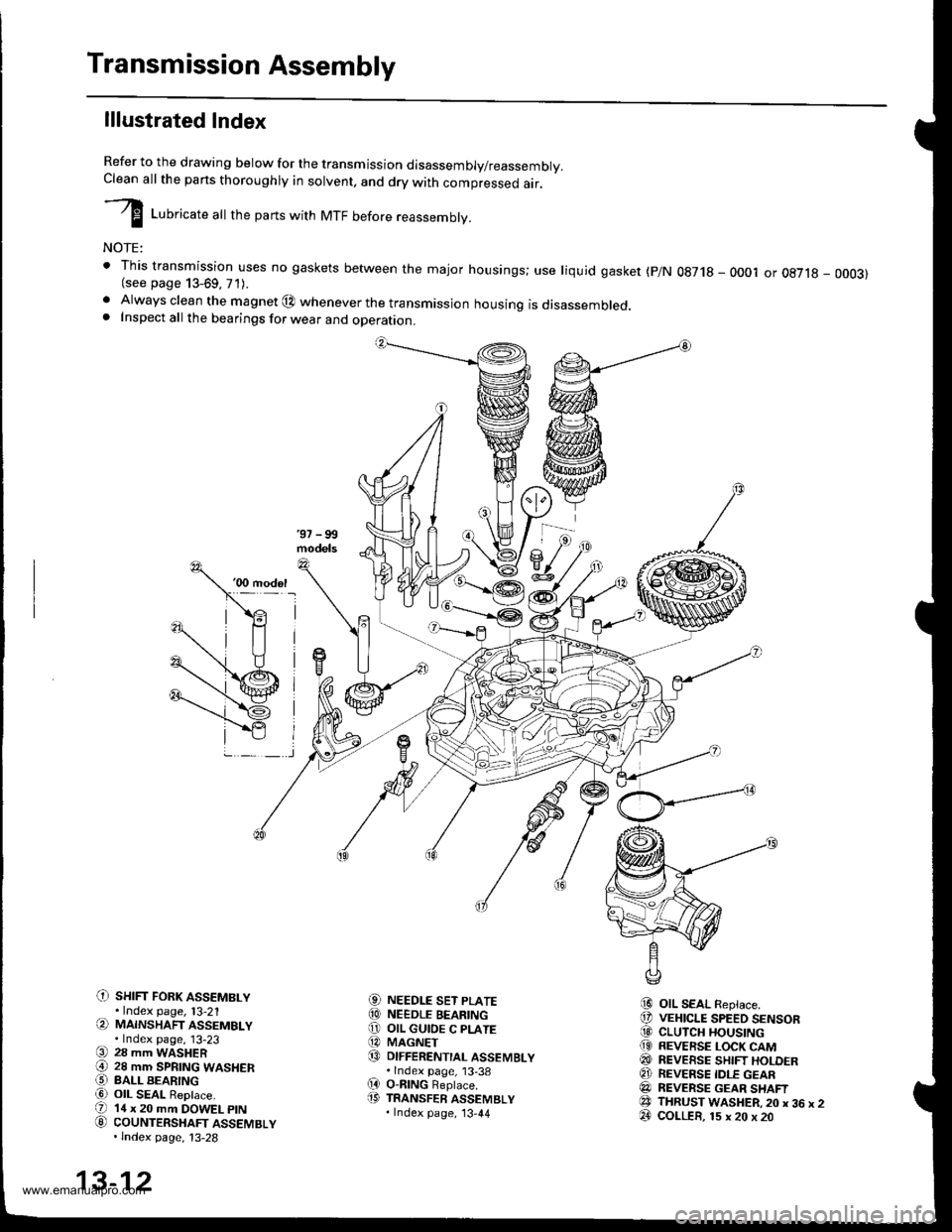
Refer to the drawing below for the transmission disassembly/reassembly.Clean all the pans thoroughly in solvent, and drv with comoressed air.
I LuUri""r" utt the parts with MTF before reassembly.
NOTE:
t This transmission uses no gaskets between the major housings; use liquid gasket (p/N 0g718 - 0001 or oE7l8 - 0003)(see page 13-69, 71).. Always clean the magnet @ whenever the transmissjon housing is disassembled.. Inspect all the bearings for wear and operation.
C) sHrFr FoRK ASSEMBLY.Index page, l3-21(a MAINSHAFT ASSEMBLY.Index page, 13-23(9 28 mm WASHER€) 28 mm SPRTNG WASHERO BALL BEARINGa6) OIL SEAL ReDlace.(D 14 x 20 mm DOWEL ptN
G) couNTERSHAFT ASSEMBLY.lndex page, 13-28
NEEDLE SET PLATENEEDLE BEARINGOIL GUIOE C PLATEMAGNETDIFFERENTIAL ASSEMBLY.lndex page, 13-38O-nlNG Beplace.TRANSFER ASSEMBLY.Index page, '13,44
OIL SEAL Replace.VEHICLE SPEED SENSORCLUTCH HOUSINGREVERSE LOCK CAMREVEESE SHIFT HOLDERREVERSE IDLE GEARREVERSE GEAR SHAFTTHRUST WASHER,20 x 36 x 2COLLER, 15 x 20 x 20
aol
@o@@
(D
i9
@@@(9
@@@e3@
13-12
www.emanualpro.com
Page 507 of 1395
Transmission Assembly
Reassembly (cont'dl
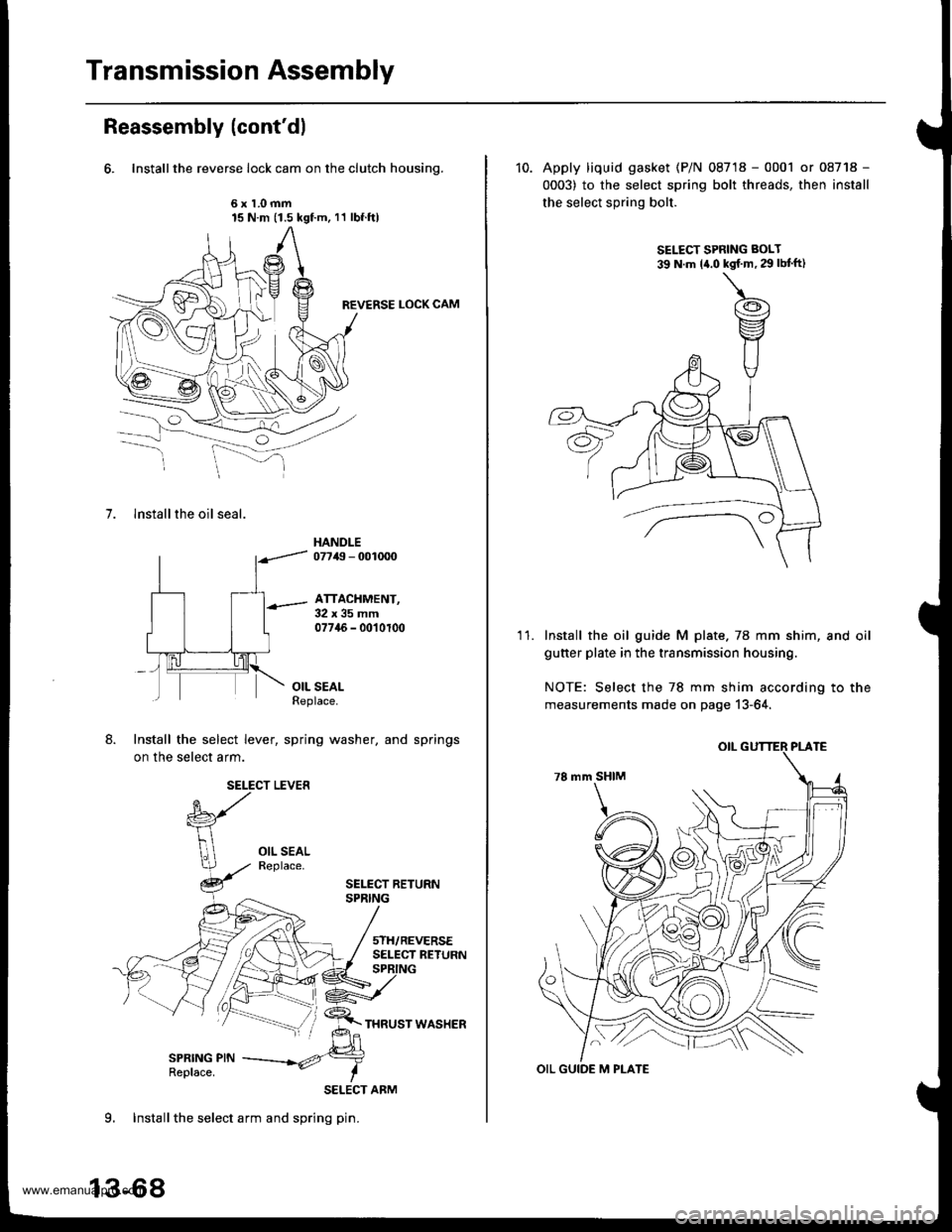
6. Installthe reverse lock cam on the clutch housing.
6x1.0mm15 N.m (1.5 kgf.m, 11 lbf.ftl
REVERSE LOCK CAM
7. lnstall the oil seal.
HANDLE07749 - 001mO
ATTACHMENT,32x35mm07745 - 0010100
OIL SEALReplace.
Install the select lever, spring washer, and springs
on the select arm.
SELECT LEVER
SELECT BETURNSPRING
5TH/REVERSESELECT RETURN
SPRING PINReplace.
SELECT ARM
9. Installthe select arm and spring pin.
13-68
10. Apply liquid gasket (P/N 08718 - 0001 or 08718 -
0003) to the select spring bolt threads, then install
the select spring bolt.
SELECT SPRING BOLT
39 N.m la.o kgf'm,29lbtft)
'I 1.Install the oil guide M plate.78 mm shim, and oil
guner plate in the transmission housing.
NOTE: Select the 78 mm shim according to the
measurements made on page 13-64,
OIL GUIDE M PLATE
www.emanualpro.com
Page 508 of 1395
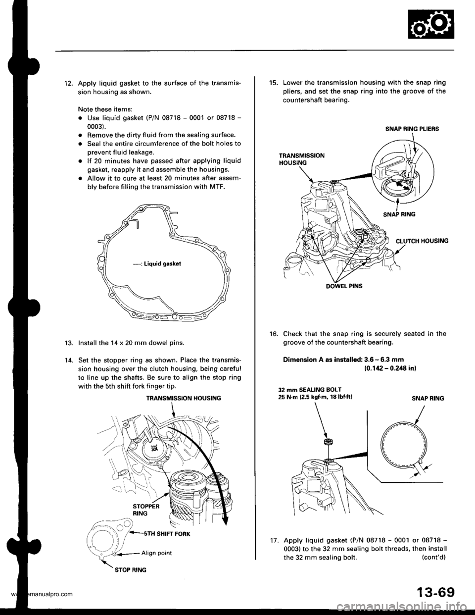
12. Apply liquid gasket to the surface of the transmis-
sion housing as shown.
Note these items:
. Use liquid gasket (P/N 08718 - 0001 or 08718 -
0003).
. Remove the dirty fluid from the sealing surface.
. Seal the entire circumterence of the bolt holes to
prevent fluid leakage.
. lf 20 minutes have passed after applying liquid
gasket, reapply it and assemble the housings.
a Allow it to cure at least 20 minutes after assem-
bly betore filling the transmission with MTF.
Install the 14 x 20 mm dowel pins.
Set the stopper ring as shown. Place the transmis-
sion housing over the clutch housing, being careful
to line up the shafts. Be sure to align the stop ring
with the 5th shift fork finger tip.
r3.
14.
TRANSMISSION HOUSING
SHIFT FORK
vk..*,
Align point
17.
the 32 mm sealing bolt.
15. Lower the transmission housing with the snap ring
pliers. and set the snap ring into the groove of the
countershaft bearing.
Check that the snap ring is securely seated in the
groove of the countershaft bearing.
Dimension A as installod: 3.6 - 6.3 mm
(0.142 - 0.2/8 in)
16.
32 mm SEALING BOLT25 N m 12.5 kgf.m, 18 lbf.ftlSNAP RING
(cont'd)
13-69
Apply liquid gasket (P/N 08718 - 0001 or 08718 -
0003) to the 32 mm sealing bolt threads, then install
SNAP RING PLIERS
DOWEL PINS
www.emanualpro.com
Page 510 of 1395
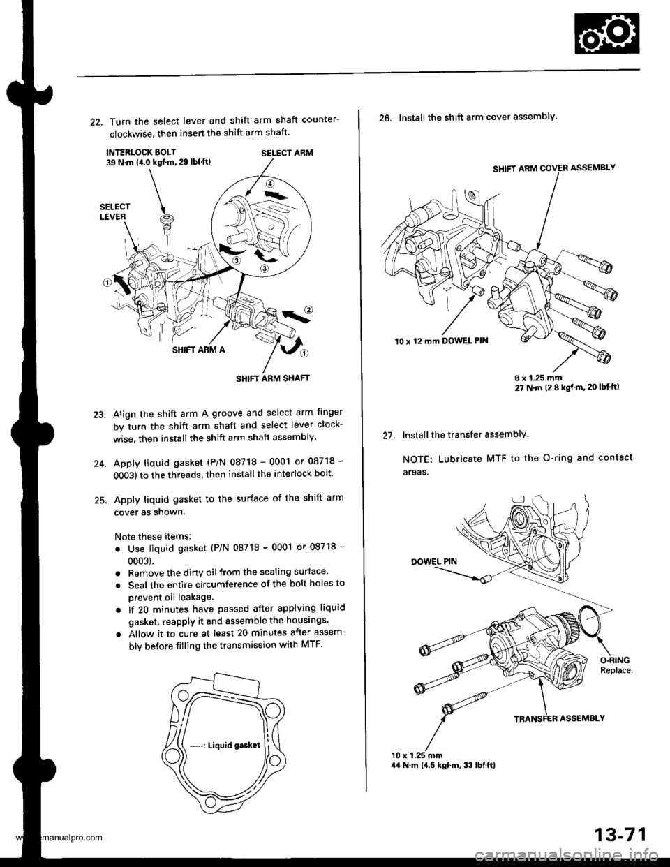
22. Turn the select lever and shift arm shaft counter-
clockwise, then insert the shift arm shaft.
INTERLOCK EOLT39 N.m (4.0 kqt ft, 29 lbf ft)SELECT ARM
SHIFT ARM A
Align the shift arm A groove and select arm finger
by turn the shift arm shaft and select lever clock-
wise. then installthe shift arm shaft assembly.
Apply liquid gasket (P/N 08718 - 0001 or 08718 -
OO03) to the threads, then install the interlock bolt'
Apply liquid gasket to the surface of the shift arm
cover as snown.
Note these items:
. Use liquid gasket (P/N 08718 - 0001 or 08718 -
0003).
. Remove the dirtv oilfrom the sealing surface.
. Seal the entire circumference of the bolt holes to
prevent oil leakage.
. lf 20 minutes have passed after applying liquid
gasket. reapply it and assemble the housings.
a Allow it to cure at least 20 minutes after assem-
bly betore filling the transmission with MTF.
23.
-->.-
(
SHIFT ARM SHAFT
SHIFT ARM COVER ASSEMBLY
10 x 12 mft DOWEL PIN
t1
26. Install the shift arm cover assembly.
I x 1.25 mm27 N m 12.8 kgt m,20 lbf'ft)
Install the transfer assemblY.
NOTE: Lubricate MTF to the O-ring and contact
areas.
10 x 1.25 mm44 N.m 14.5 kgf.m, 33 lbl.ftl
13-71
www.emanualpro.com
Page 513 of 1395
Transmission Assembly
Installation (cont'dl
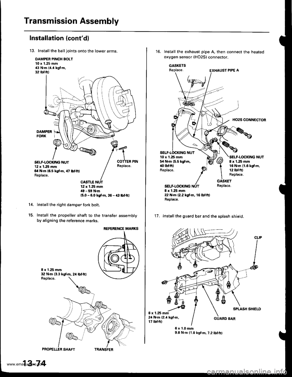
13. Installthe balljoints onto the lower arms.
DAMPER PINCH BOLT10 x 1.25 mm43 N.m {a.a kgf.m,32 rbfft)
SELF.LOCKING NUT'12 x 1.25 |nm6il N'm 16.5 kgtin, 47 lbtftlReolace.
Replace.
14.
PROPELI"ER SHAFT
13-74
12 x 1.25 mm,19 - 59 N.m(5.0 - 6.0 kgi.m, 36 - € lbfttl
Install the right damper fork bolt.
Install the propeller shaft to the transfer assembly
by aligning the reference marks.
E x 1.25 mr'|
15.
REFERENCE MARKS
32 N.m 13.3 kst m, 2a lbf.ftl
TRANSFER
Install the exhaust pipe A, then connect the heated
oxygen sensor (HO2S) connector.
GASKETSReplace.
HO2S CONNECTOR
10 x 1.25 mm5,1N.m 15.5 kgtm.() tbt filReplace.
SELF.LOCKING
SELF.LOCKING NUT8 x 1.25 mm16 N.rn 11.6 kg{.m,12lbtfr)Replace.
GASKETReplace.
8 x 1.25 rr|ln22 N.m (2.2 tgf.m, 16 lbl.ftlReplac6.
'17. Installthe guard bar and the splash shield.
SPLASH SHIEI.I)I x 1.25 mm24 N.m l2.a kgf.m.17 tbtft)GUARD BAR
6x1.0mm9.8 N.m (1.0 kgf.m, 7.2 lbf.ft)
www.emanualpro.com
Page 654 of 1395
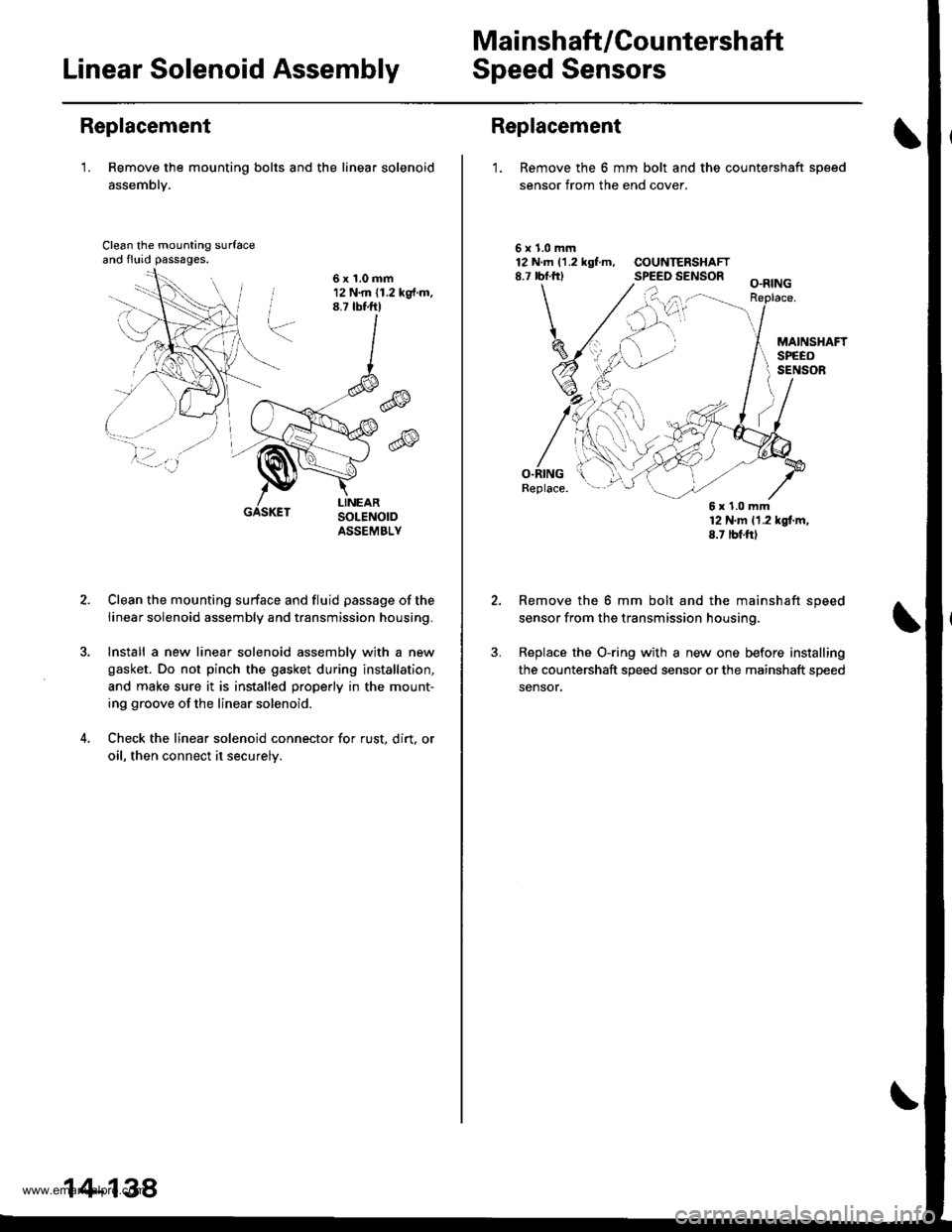
Mai nshaft /Cou ntershaft
Linear Solenoid AssemblySpeed Sensors
Replacement
'1. Remove the mounting bolts and the linear solenoid
assemblY.
Clean the mounting surfaceand fluid passages.
6x1.0mm12 N.m (1.2 kg{.m.8.7 tbtftl
@
@
GASKET
Clean the mounting surface and fluid passage of the
linear solenoid assembly and transmission housing.
Install a new linear solenoid assemblv with a new
gasket. Do not pinch the gasket during installation,
and make sure it is installed properly in the mount-
ing groove of the linear solenoid.
Check the linear solenoid connector for rust. dirt, or
oil, then connect it securelv.
14-138
Replacement
1. Remove the 6 mm bolt and the countershaft sDeed
sensor from the end cover.
\
5x1.0mm12 N.m 11.2 kgf.m, COUNTERSHAFT8.7 rbf.frl SPEED SENSOR
O.RINGReplace.
12 N'm 11.2 kgl.m,8.7 tbf.ftl
Remove the 6 mm bolt and the mainshaft speed
sensor from the transmission housing.
Replace the O-ring with a new one before installing
the countershaft speed sensor or the mainshaft speed
sensor,
6x1.0mm
www.emanualpro.com
Page 684 of 1395
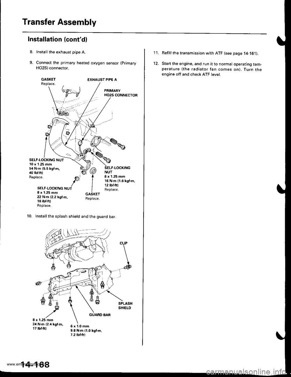
Transfer Assembly
Installation (cont'dl
Install the exhaust pipe A.
Connect the primary heated oxygen sensor (Primary
H02S) connector,
GASKETReplace.EXHAUST PIPE A
SELF.LOCKING NUT10 x 1.25 mm54 N.m {5.5 kgf.m,40 rbf.ft)Replace.
NUT8 x 1.25 mm16Nm11.6kgf.m,12 lbf.fOReplace.
-LOCKING
SELF-LOCKING NUT8 x 1.25 mm22 N.m (2.2 kgl.m,16 rbr.fttReplace.
10. Installthe splash shield and the guard bar.
6x1.0mm9.8 N.m {1.0 kgt.m,7.2 tbt.ftt
14-168
'I '�I.
12.
Refillthe transmission with ATF (see page 14-161).
Start the engine, and run it to normal operating tem-perature (the radiator fan comes on), Turn theengine off and check ATF level.
www.emanualpro.com
Page 693 of 1395
![HONDA CR-V 1999 RD1-RD3 / 1.G Workshop Manual
r] REVERSE IDLER GEAR SHAFT/HOLDERA N€EDLE BEARING
..] TRANSMISSION HOUSING
al TRANSMISSION HOUSING OIL SEAL Replace.g SET BING.80 mm Selecrive part
O REVERSE GEAR COLLABE couNTERSHAFT REVERSE GEA HONDA CR-V 1999 RD1-RD3 / 1.G Workshop Manual
r] REVERSE IDLER GEAR SHAFT/HOLDERA N€EDLE BEARING
..] TRANSMISSION HOUSING
al TRANSMISSION HOUSING OIL SEAL Replace.g SET BING.80 mm Selecrive part
O REVERSE GEAR COLLABE couNTERSHAFT REVERSE GEA](/img/13/5778/w960_5778-692.png)
r] REVERSE IDLER GEAR SHAFT/HOLDER'A N€EDLE BEARING
..] TRANSMISSION HOUSING
al TRANSMISSION HOUSING OIL SEAL Replace.g SET BING.80 mm Selecrive part
O REVERSE GEAR COLLABE couNTERSHAFT REVERSE GEAB
.9,] NEEDLE BEARINGi9 LOCK WASHER Replace..1!i REVERSE SHIFT FORKO REVERSE SELECToRiJ. REVERSE SELECTOR HUBii' COUNTERSHAFT 4TH GEAR.14 NEEDLE BEARINGiD D|STANCE coLLAR,28 mm Selective part(i3 COUNTERSHAFT 2NO GEABi7-] THRUST NEEDLE BEARING(10 COUNTERSHAFT 3RD GEAR(9 NEEDLE BEARINGE9 COUNTERSHAFI3RD GEAB COLLAR.li THRUST NEEDLE BEARING.?) SPLINEO WASHER,,O 3RD CLUTCH ASSEMBLY
€1 O-RING Beplace.i23 COUNTERSHAFT
4i SHIFT CONTROL SOLENOID COVER
?Z] HARNESS CLAMP BRACKET
?9] SHIFT CONTROL SOLENOID VALVE A/B ASSEMBLY
8 HARNESS CLAMP BRACKET
GI SHIFT CONTROL SOLENOID VALVE FILTER/GASKET
(4 MAINSHAFT 2ND GEARi49 NEEDLE BEARING
@ THRUST NEEDLE BEARING(49 MAINSHAFT
@r SEAL|NG R|NG,35 mm
O SEALING RING,29 mm
@ NEEDLE BEARING
.49 SET RING
€) lST.HOLD CLUTCH ASSEMBLY
O o-RING Replace.6E THRUST WASHER
€9 THRUST NEEDLE BEARING
6' NEEDLE EEARING
€ir SUB-SHAFT 4TH GEAR
6 THRUST NEEDLE BEARING
@ SUB.SHAFT 4TH GEAR COLLAR@ sUB-sHAFf
6I NEEDI-E B€ARING STOP
@ NEEDLE BEARING(6t ATF GUIDE CAP Replace.(64 TRANSMISSION HANGEB
@ BREATHER CAP
i@ MAINSHAFT SPEED SENSOR
6i O-RING Replace.
6D REVERSE IDLER GEAR
@r DOWEL PlN, 14 x 25 mm.6d SNAP RINGS
QlI SUB.SHAFT TRANSMISSION HOUSING BEARING
E) MAINSHAFT TRANSMISSION HOUSING BEABING.2, COUNTERSHAFI TRANSMISSION HOUSINGBEARING
@[E
t,n9t0@)@),lD
04
@
@@:���������������.ro)
ai
Replace-SNAP RINGTHRUST WASHEBTHRUST NEEDLE BEARINGMAINSHAFT 4TH GEARNEEDLE BEARINGSTHRUST NEEDLE BEARINGMAINSHAFT 4TH GEAB COLLAR2NO/4TH CLUTCH ASSEMBLYO-RING Replace.THRUST WASHER,36.5 x 55 mm Selective partTHRUST NEEOLE BEARING
DOWEL PlN, 14 x 25 mmCONNECTOR BRACKETATF MAGNETDOWEL PlN, 14 x 20 mmTRANSMISSION HOUSING GASKET Replace.DIFFERENTIAL ASSEMBLYDOWEL PlN, 10 x 12 mmO-RING Replace.TRANSFER ASSEMBLYTOROUE CONVERTER HOUSING OIL SEAL Replace.TOROUE CONVERTER HOUSING
TOROUE SPECIFICATIONS
Bolt/Nut No.Torque ValueSizeRgmarks
6A
6B
10A
12 N.m (1.2 kgf.m,8.7 lbf.ft)
14 N.m (1.4 kgf.m, 10 lbift)
44 N.m (4.5 kgf.m,33 lbf.ft)
6x 1.0 mm
6x 1.0 mm
10 x 1.25 mm
14-177
www.emanualpro.com