Transmission speed sensor HONDA CR-V 1999 RD1-RD3 / 1.G Workshop Manual
[x] Cancel search | Manufacturer: HONDA, Model Year: 1999, Model line: CR-V, Model: HONDA CR-V 1999 RD1-RD3 / 1.GPages: 1395, PDF Size: 35.62 MB
Page 89 of 1395

Disconnest the lilP connector from the control unit.
Csvity WireTest condition
R€conn€ct tho 14P connGctor to the control unit.
Test: Desired resultPossible cause it result is not obtained
BRNAr'VHTUnder all conditionsCheck for resistance to groundl
There should be 80 - 120 o.
Faulty actuator solenoid
Poor ground (G202)
An open in the wire1BRNUnder all conditionsCheck for resistance to groundl
There should be 40 - 60 0.
11BRN/BLKUnder all conditionsCheck for resistance to ground:
There should be 70 - 110 O.
2GRY
lgnition switch ON (ll),
main switch ON and
brake pedal depressed,
then released
Check for voltage to ground:
There should be 0 V with the pedal
depressed and battery voltage with
the pedal released.
. Faulty brake switch. An open in the wire
BLKUnder all conditionsCheck for continuity to ground:
There should be continuity.
. Poor ground (G401). An open in the wire
5GRNMHT
Brake pedal depressed,
then released
Check for voltage to ground:
There should be battery voltage with
the pedal depressed, and 0 V with
the pedal released.
Blown No.52 1'15 Alfuse in the
under-hood fuse/relay box
Faulty brake switch
An open in the wire
LT GRN/
RED
Set button pushedCheck for voltage to ground:
There should be battery voltage.Blown No. 52 {'15 A} fuse in the
under-hood fuse/relay box
Faulty horn relay
Faulty sevresume switch
Faulty cable reel
An open in the wire7LT GRN/
BLK
Resume button pushed
10RED/BLU
lgnition switch ON lll)Attach to ground:
Cruise indicator light in the gauge
assembly should come on.
Elown bulbBlown No. 25 (7.5 A) tuse in theunder-dash fuse/relay box
Faulty dimming circuit in the gauge
assembly
An open in the wire
ELU^r'r'HT
lgnitjon switch ON {ll}and main switch ON;
raise the front of the
vehicle, block one wheel
and rotate the other
wheel slowly.
Check for voltage between the
ELUA/VHT @ and BLK O terminalsl
There should be 0 - 5 V or more-0 - 5 V or more repeatedly.
Faulty vehicle speed sensor (VSS)
An open in the wire
r3LT GRN
lgnition switch ON {ll}and main switch ONCheck for voltage to ground:
There should be battery voltage.
Blown No. 14 (7.5 A) fuse in theunder-dash fuse/relay box
Faulty main switch
An open in the wire
l4PNK
A'/T: Shift lever in E, EotE
lvl/T: Clutch pedal
releaseo
Check for continuity to ground:
There should be continuity.NOTE: There should be no continu-
ity when the shift lever is in otherpositions or when the clutch pedal is
oepresseo.
Faulty A/f gear position switch 1A,/TlFaulty or misadjusted clutch switch
fi{/r)Poor ground (G101)
An open in the wire
BLU
Start tho engine. turnthe main switch ON, anddrive the vehicle over 25
mph (40 km/h)with the
crurse control set
Check for voltage to ground:
There should be approx.5 V
. Faulty cruise control unit. Shod to ground
*: '98 - 00 models with Automatic Transmission.
4-39
www.emanualpro.com
Page 267 of 1395
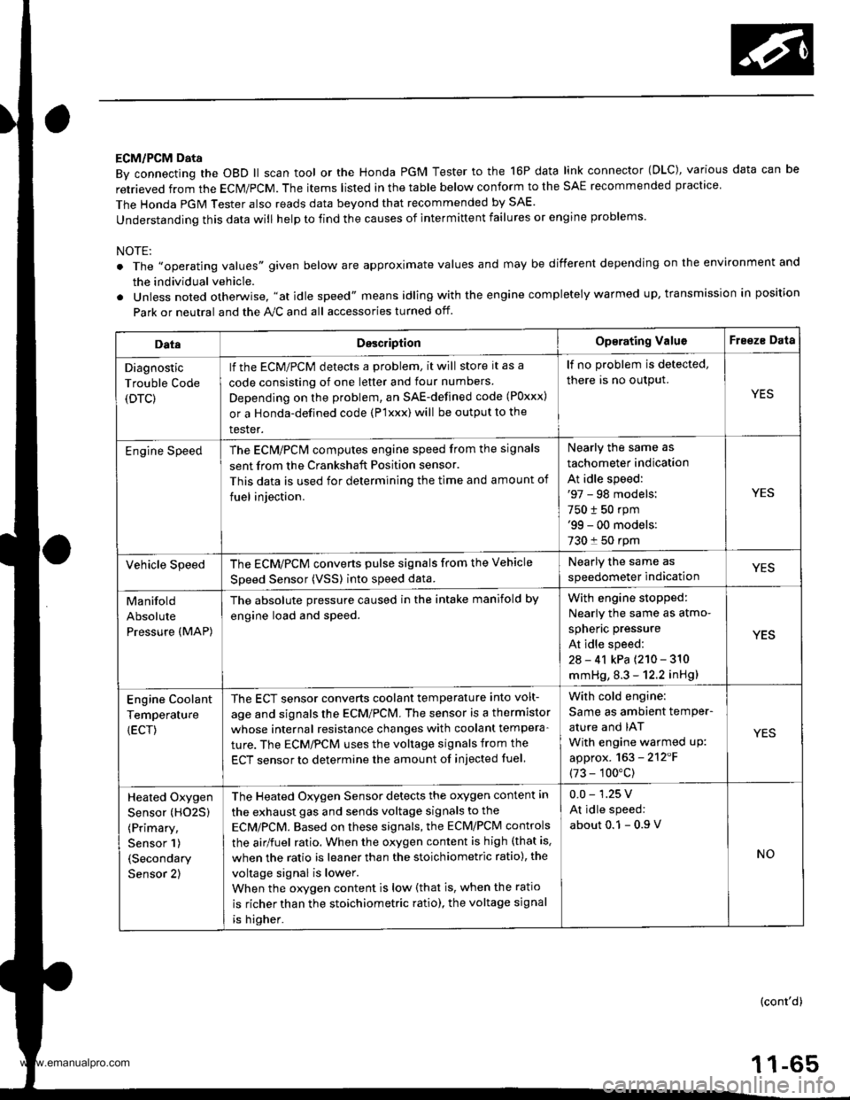
ECM/PCM Data
By connecting the OBD ll scan tool or the Honda PGM Tester to the 16P data link connector (OLC), various data can be
retrieved from the ECM/PCM. The items listed in the table below conform to the SAE recommended practice
The Honda PGM Tester also reads data beyond that recommended by SAE.
understanding this data will help to find the causes of intermittent failures or engine problems.
NOTE:
The ',operating values" given below are approximate values and may be different depending on the environment and
the individual vehicle.
Unless noted otherwise. "at idle speed" means idling with the engine completely warmed up, transmission in position
Park or neutral and the A,./C and all accessories turned otf.
DataDesc.iptionOp€rating ValuoFreeze Data
Diagnostic
Trouble Code
(DTC)
lf the ECM/PCM detects a problem, it will store it as a
code consisting of one letter and tour numbers
Depending on the problem, an SAE-defined code (Poxxx)
or a Honda-defined code (P'lxxx) will be output to the
tester.
lf no problem is detected,
there is no output.
YES
Engine SpeedThe ECN4/PCN4 computes engine speed from the signals
sent from the Crankshaft Position sensor.
This data is used for determining the time and amount of
fuel iniection.
Nearly the same as
tachometer indication
At idle speed:'97 - 98 models:
750 t 50 rpm'99 - 00 models:
730 f 50 rpm
YES
Vehicle SpeedThe ECM/PCM converts pulse signals from the Vehicle
Speed Sensor (VSSI into speed data.
Nearly the same as
speedometer indicationYES
Manifold
Absolute
Pressure (MAP)
The absolute pressure caused in the intake manifold by
engine load and speed.
With engin6 stopped:
Nearly the same as atmo-
spheric pressure
At idle speed:
2a - 41 kPa {210 - 310
mmHg, 8.3 - 12.2 inHg)
YES
Engine Coolant
Temperature
{ECT)
The ECT sensor converts coolant temperature into volt-
age and signals the ECM/PCM. The sensor is a thermistor
whose internal resistance changes with coolant tempera-
ture. The ECM/PCM uses the voltage signals from the
ECT sensor to determine the amount of injected fuel
With cold engine:
Same as ambient temPer-
ature and IAT
With engine warmed uP:
approx. 163 - 2'12'F
(73 - 100"c)
YES
Heated Oxygen
Sensor (HO25)
(Primary,
Sensor 1)
(Secondary
Sensor 2)
The Heated Oxygen Sensor detects the oxygen content in
the exhaust gas and sends voltage signals to the
ECMiPCM. Based on these signals, the ECM/PCM controls
the airlfuel ratio. When the oxygen content is high (that is.
when the ratio is leaner than the stoichiometric ratio), the
voltage signal is lower.
When the orygen content is low (that is, when the ratio
is richer than the stoichiometric ratio), the voltage signal
is higher.
0.0 - 1.25 V
At idle speed:
about 0.1 - 0.9
NO
(cont'd)
1 1-65
www.emanualpro.com
Page 282 of 1395

PGM-FI System
System Description
INPUTS
CKP/TDC/CYP Sensor
CKF Sensor
MAP Sensor
ECT Sensor
IAT Sensor
TP Sensor
Primary HO2S
Secondary H02S
vss
KS*5
BARO Sensor
ELD*6
Starter Signal
ALT FR Signal
Air Conditioning Signal
Ay'T Gear Position Signal*1
Baftery Voltage (lGN.1)
Brake Switch Signal
PSP Switch Signal
Fuel Tank Pressuae Sensor*4. *5
Countershaft Speed Sensor*1
Mainshaft Speed Sensor*r
OVER-DRIVE Switch Signal*s
ENGINE CONTROL MODULE (ECM)/
POWERTRAIN CONTROL MODULE (PCM) OUTPUTS
|iuel 1"j""- Th,rhg ""d Drrafr";-l
Et*-.nt"tdt"cont.orl
to,r*,c;;trffi;]
l.----.---:. .Lrgnrnon |lmrng Lonrror I
Ecir/PcM B*k',p Fr""il]
m;"t-ll-r*'io*l
Fuel Injectors
PGM-Fl Main Relay (Fuel Pump)
MIL
IAC Valve
Ay'C Compressor Clutch Relay
Radiator Fan Relay
Condenser Fan Relay
ALT
tcM
EVAP Purge Control Solenoid
Valve
Primary HO2S Heater
Secondary H02S HeaterEVAP Bypass Solenoid Valve*a *5
EVAP Control Canister Vent Shut
DLC
Lock-up Control Solenoid Valve*l
Shift Control Solenoid Valve*1
Ay'T Clutch Pressure Control
Solenoid Valve*1
D4 Indicator Light'1 *3, *a
D Indicator Light,l *5
OVER-DRIVE OFF Indicator
Lighl*t *:
*1: A/T {3:'97 model'2: M/f +4:'98 model*5: '99 - 00 models"6: USA
PGM-Fl System
The PGM-Fl system on this model is a sequential multiport fuel injection system.
Fuel iniecior Timing and Duration
The ECM/PCM contains memories for the basic discharge durations at various engine speeds and manifold pressure. The
basic discharge duration, after being read out from the memory, is further modified by signals sent from various sensors
to obtain the final discharge duration.
ldle Air Control
ldle Air Control Valve (lAC Valve)
When the engine is cold, the Ay'C compressor is on, the transmission is in gear, the brake pedal is depressed, the P/S load
is high, or the alternator is charging, the ECM/PCM controls current to the IAC Valve to maintain the correct idle speed.
lgnition Timing Control
o The ECM/PCM contains memories for basic ionition timing at various engine speeds and manifold air flow rates.
lgnition timing is also adjusted for engine coolant temperature.
. A knock control system was adopted which sets the ideal ig nition timing for the octane rating of the gasoline used.*s
Other Control Funstions
1. Starting Control
When the engine is started. the ECM/PCM provides a rich mixture by increasing fuel injector duration.
2. Fuel Pump Control
. When the ignition switch is initially turned on (ll). the ECMiPCM suppli€s ground to the PGM-FI main relay that
supplies current to the fuel pump for two seconds to pressurize the fuel system.
. When the engine is running, the ECM/PCM supplies ground to the PGM-FI main relay that supplies current to the
fuel oumo.
. When the engine is not running and the ignition is on, the ECM/PCM cuts ground to the PGM-FI main relay which
cuts current to the fuel pump.
1 1-80
www.emanualpro.com
Page 407 of 1395

'97 model:
The scan tool indicates Diagnostic Trouble Code (DTC) P0441: Evaporative Emission (EVAP) control system
insufficient purge flow.
Description
By monitoring the purge line vacuum with the MAP sensor, the PCM can detect insufficient EVAP control system purge
flow.
Possiblo Cause
. EVAP Purge Control Solenoid Valve
. EVAP Purge Control Solenoid Valve Circuit
. EVAP Control Canister
. Vacuum Lines
. PCM
Troubleshooting Flowchart
EVAP PURGE CONTROL
SO1TNOID VALVE 2P
CoNNECTOR (C108)
(v)
YL
Wire side of female
termrnals
(cont'd)
11-205
Th€ MIL has b€en reooited on.DTC P0441 is .tored.
Problem verificationl1. Start the engine. Hold theengine at 3,000 rpm with noload (in Park or neut.al) untilthe radiator fan comes on.2. Do the PCM Reset Procedure.3. Connect the SCS service con-nector,4. Test drive under following con'ditions on the road.- without any electrical load- Transmission in @ or @position- Engine speed between1 ,2OO - 2,4OO rpfi.- Decelerate from 50 mph (80
km/h)to 15 mph (24 km/h)Intermittent trilure, sydern is OKat this time. Check for Door con-nections or loose wir€3 at C108
IEVAP purge control solonoidvalvol .nd at the PCM.
ls DTC P0441 indicated?
Check tor an open in the wire (lcl
linel:1. Turn the ignition switch OFF.2. Disconnect the EVAP purge
control solenoid valve 2P con-nector.3. Turn the ignition switch ON (ll).
4. Measure voltage between bodyground and the EVAP purge
control solenoid valve 2P con-nector terminal No. '1,
R€pafu open in thc wir6 b€tw€enthG EVAP purge control solenoidvalve and the No. 15 ALTEBNA-TOR SP SENSOR (7.5 A)fuse.
ls there batlery voltage?
(To page 11'206)
www.emanualpro.com
Page 447 of 1395
Transmission Assembly
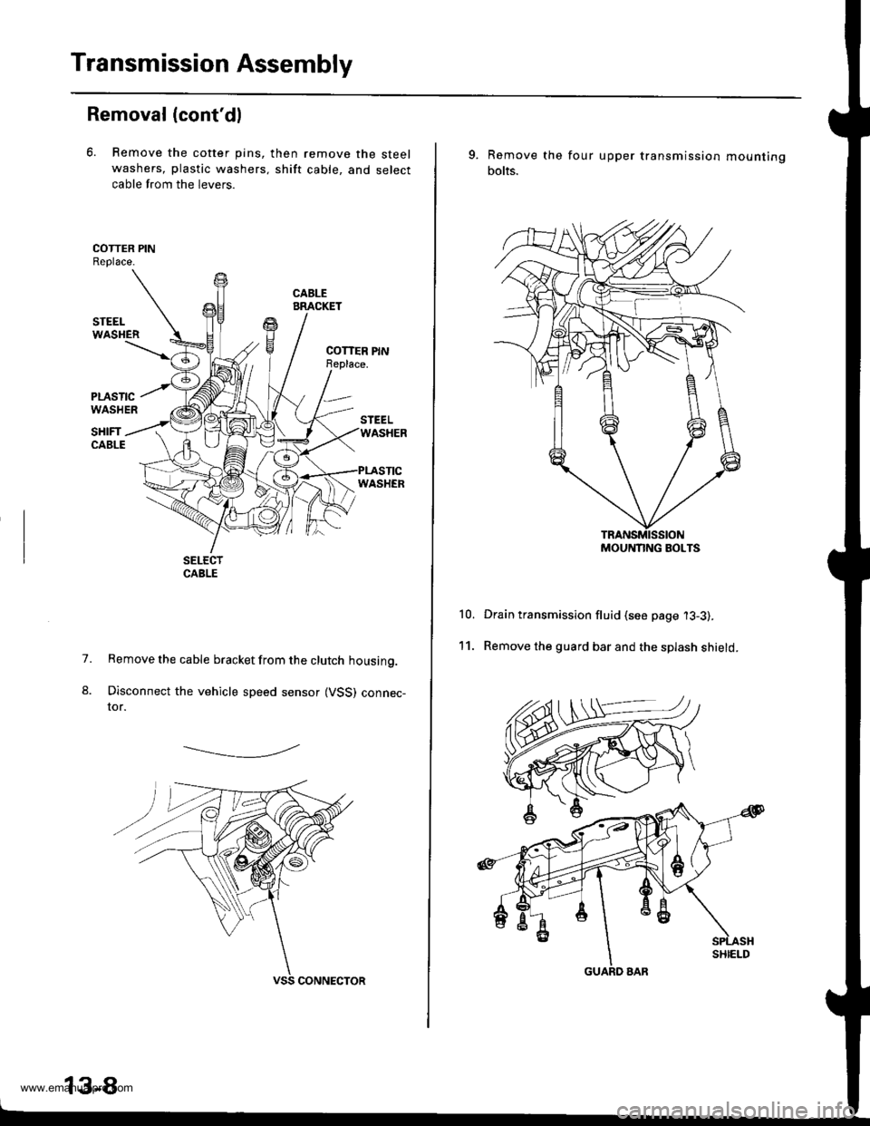
Removal (cont'dl
6. Remove the cotter pins,
washers, plastic washers.
cable from the levers.
then remove the steel
shift cable, and select
1.
8.
Remove the cable bracket from the clutch housing.
Disconnect the vehicle speed sensor (VSS) connec-tor.
-------------.2
13-8
9. Remove the
bolts.
four upper transmission mou nting
10.
11.
Drain transmission fluid (see page '13-3).
Remove the guard bar and the splash shield.
MOUNNNG BOLTS
www.emanualpro.com
Page 451 of 1395
Transmission Assembly
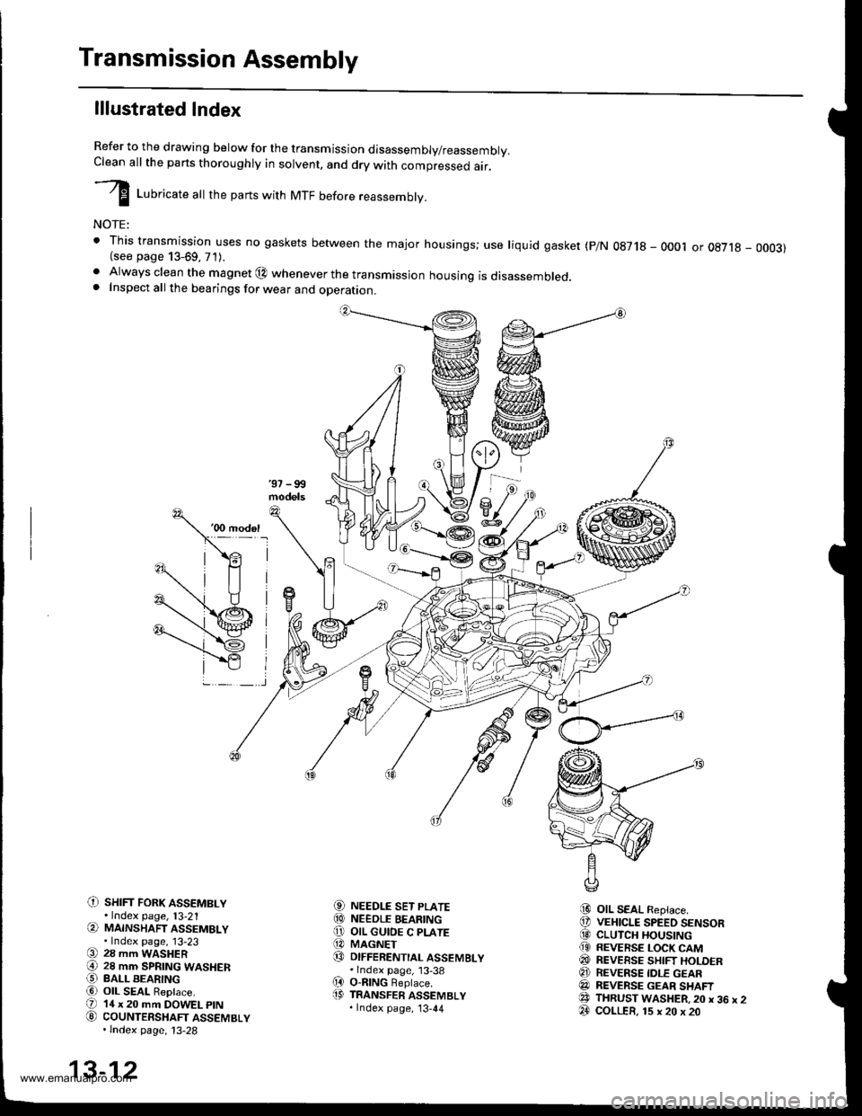
lllustrated Index
Refer to the drawing below for the transmission disassembly/reassembly.Clean all the pans thoroughly in solvent, and drv with comoressed air.
I LuUri""r" utt the parts with MTF before reassembly.
NOTE:
t This transmission uses no gaskets between the major housings; use liquid gasket (p/N 0g718 - 0001 or oE7l8 - 0003)(see page 13-69, 71).. Always clean the magnet @ whenever the transmissjon housing is disassembled.. Inspect all the bearings for wear and operation.
C) sHrFr FoRK ASSEMBLY.Index page, l3-21(a MAINSHAFT ASSEMBLY.Index page, 13-23(9 28 mm WASHER€) 28 mm SPRTNG WASHERO BALL BEARINGa6) OIL SEAL ReDlace.(D 14 x 20 mm DOWEL ptN
G) couNTERSHAFT ASSEMBLY.lndex page, 13-28
NEEDLE SET PLATENEEDLE BEARINGOIL GUIOE C PLATEMAGNETDIFFERENTIAL ASSEMBLY.lndex page, 13-38O-nlNG Beplace.TRANSFER ASSEMBLY.Index page, '13,44
OIL SEAL Replace.VEHICLE SPEED SENSORCLUTCH HOUSINGREVERSE LOCK CAMREVEESE SHIFT HOLDERREVERSE IDLE GEARREVERSE GEAR SHAFTTHRUST WASHER,20 x 36 x 2COLLER, 15 x 20 x 20
aol
@o@@
(D
i9
@@@(9
@@@e3@
13-12
www.emanualpro.com
Page 453 of 1395
Transmission Assembly
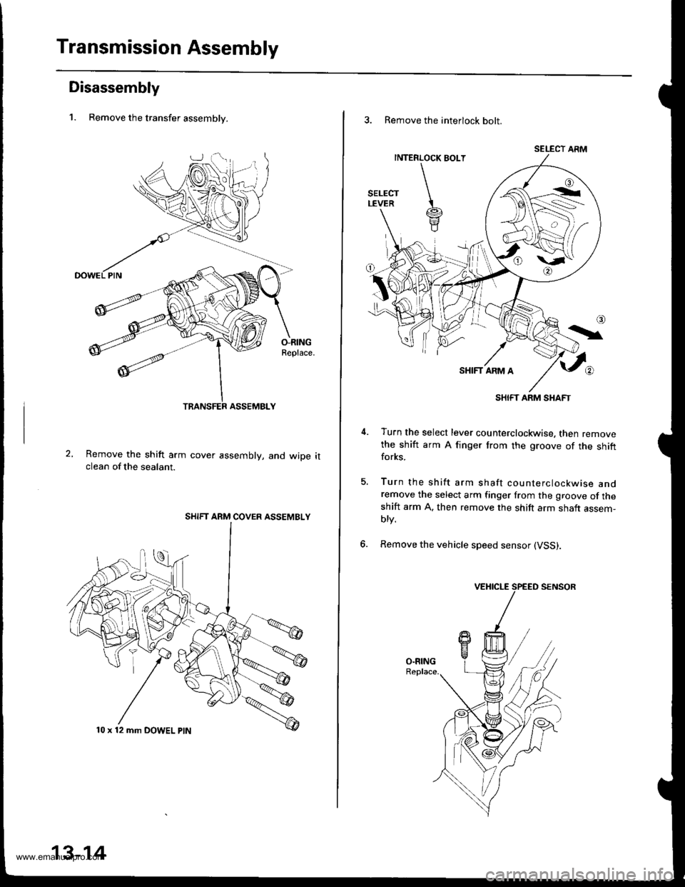
Disassembly
1. Remove the transfer assemblv.
O-RINGReplace.
Remove the shift arm cover assembly, and wiDe itclean of the sealant.
SHIFT ARM COVER ASSEMBLY
10 x 12 mm DOWEL ptN
13-14
3. Remove the interlock bolt.
SELECT ARM
SHIFT ARM SHAFT
Turn the select lever counterclockwise, then removethe shift arm A finger from the groove of the shiftforks.
Turn the shift arm shaft counterclockwise andremove the select arm finger from the groove of theshift arm A. then remove the shift arm shaft assem-blv.
Remove the vehicle speed sensor (VSS).
5.
6.
www.emanualpro.com
Page 509 of 1395
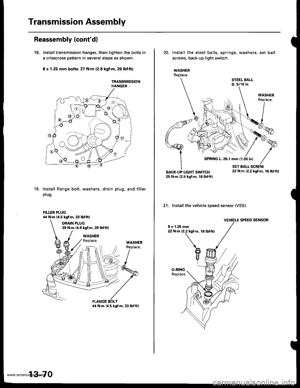
Transmission Assembly
Reassembly lcont'd)
18. Installtransmission hanger, then tighten the bolts in
a crisscross pattern in several steps as shown.
8 x 1.25 mm bolis: 27 N.m 12.8 kgf.m,20 lbf'ft}
TRANSMISSIONHANGER
19.Install flange bolt,
plug.
washers, drain plug. and filler
FILLER PLUG4,r N.m (a.5 kgl.m,33lbtftl
DRAIN PLUG39 N.m {4.0 kg{.m,29lbtftl
WASHERReplace.WASHER
13-70
20. Install the steel balls, springs. washers, set ball
screws, back-up light switch.
WASHERReplace.
STEEL BALLD,5/16 in
21. Installthe vehicle speed sensor (VSS).
VEHICI."E SPEED SENSOR
8 x 1.25 mm22 N.m 12.2 kgl.m, 16 lbt.ftl
SPRING L.26.1 mm 11.03 inl
www.emanualpro.com
Page 514 of 1395
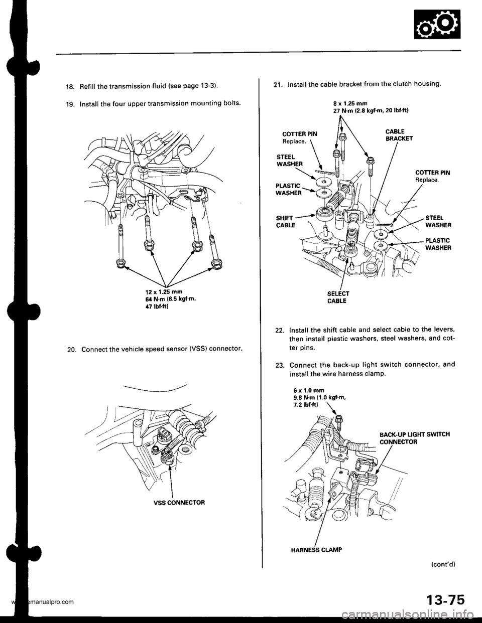
18.
19.
Refill the transmission fluid (see page 13-3)
Install the four upper transmission mounting bolts.
12 x 1.25 mm6it N.m 16.5 kgf m,il7 lbf.ftl
20. Connect the vehicle speed sensor (VSS) connector.
------------,-
VSS CONNECTOR
21, Install the cable bracket from the clutch housing.
8 x 1.25 mm27 N.m (2.8 kgt'm. 20 lbtftl
COTTER PINR€place.
STEELWASHER
COTTEN PINReplace.
STEELWASHER
PLASTICWASHER
22.
)a
SELECTCABLE
lnstall the shift cable and select cable to the levers,
then install plastic washers, steel washers, and cot-
ter prns,
Connect the back-up light switch connector. and
install the wire harness clamP.
6x1.0mm9.8 N.m {1.0 kgf.m,
HARNESS CLAMP
(cont'd)
13-75
www.emanualpro.com
Page 517 of 1395

Automatic Transmission
Special Tools . 14'2OescriptionGeneral Operation . .... 14 3Power Flow . . .. '14_6
Electronic Control System .. .. . . .. .14_15Hydraulic Control .. 14 24Hydraulic Flow....-....... .. . .... .. .. . 14_29Lock'up Syslem .. .'t4'39Electrical SystemComponenl Locdlrons 14 45
PCM Circuil Dragram (A/T Control Svstem)'97 Model ....................... . . .. - . ... .14-46'98Model ................. . ... .. .. .1450'99 00Models.... . .... . . . 1452
PCM Terminal Voltage/Measuring ConditionsA"/T Control System-'97Model ...... ..14'48A,/T Control System -'98 00 Models . . .. . . 14 54
Troubleshooting Procedures .. ..... ... - 14_56Svmotom to comoonent CharlEiectr,cal Syslem -'97 Model . . 14 60Electrical System -'98 - OO Models . .. . . 14_62Electrical Troubleshooting ('97 Model)Troubleshooting Flowaharts .... ..... . .. . . 14_64
Electrical Troubleshooting ('98 - 00 Models)Troubleshootinq Flowclt"n" .... . ....- . .14-93ElectricalTroublesliooting('99 00Models)Troubleshootino FlowchartO/D OFF Indicator Light Does Not Come On 14 131
O/D OFF Indicator Liaht On ConstantlY . . . .1!-132O/D OFF Indicator Light Does Not Come OnEven Though O/D Switch ls Pressed . .... - 14_133
Lock up Control Solenoid Valve A,/B AssemblyTest....................-......... . .14-135Replacement . .ll_135Shifr ControlSolenoid Valve Ay'B Assembl,Test .............................. . .. 14-136
Replacement..............- . .14'136Linear Solenoid AssemblYTest.............................................. .. .... . 14_137Replacement .. . 14138Marnshaftlcountershafl Speed SensorsReplacement ...-... 14_138A/T Gear Position SwitchTest ..........................-... . .. 14-139ReplacementA/T Gear Positionlndicator.................. 14-140
Valve Eodynepair ............................... ..... . . .. - . .. ... 14 192
Assembly .................... .. 1{_193
Valve CapsDesciiption....-........................ .. ...... 14194
tnspeition ................... .. 14' 195
N4ain Valve BodyDisassembly/lnspection/Reassemblv - ...... .. 14_196
Secondarv Valve BodYDisassemblv4nspectron/ReassemblY .. . 14 198
Reoulator Valve Bodvbisassembtv,lnspiction/Reassemblv . 14199
Servo EodvDisassembly/lnspection/Reassembly ... ....14'200
Lock'uo Valve BodYDis;ssembly/lnspection/Reassembly .... . 14_201
MainshaftDisassembly/lnspection/Reassembly .. .. .. ..14'202
Inspection ....-.............. ..11_203
Sealing RingsReilaceient ...... ..... . 14'204
CountershaftDisassembly/lnspection/Reassembly .. . . . . . 11-205
Disassembly/Reassemb|y . . ........ ...... . .. 14_206Inspedron ................ . .... . 14 207
One wav ClutchDisassembly/lnspection/ReassemblY ... 11_209
Sub-shaftDisassembly/lnspection/Reassembly ... . .. . 14-210
oisassembly/Re6ssembly . . ... .-...... . . ..14-211
Sub-shaft BearingsReplacement .......14'212
Clutchllfustrated Index .......... . . .14-213
Disassembly .... .. .....14-216Reassembfy .... . .. .. . 14'218
Differentialllfustrated Index " 14-222Backlash Inspection . .... . .14'223
Bearing Repiacement .. 11-223
Differe-ntial Carrier Replacement .. .. . . . .. ..11-2?4
OifSeal Replacement. . .. 14'225
Side Clearance lnspection . . - .. ... . - ...... . .. 11'226
Transmission Housing BearingsMainshaJVCountershaft EearingsRepfacement .......14221Sub'siralt Eearing Replacement . . . . . . . . . ..11'224
Toroue Converter Housing BearingsMainshattEearing/OilSe6lReplacement . .. l4229
Countershaft Bea;ing Replacement.. .... .. ..14-230
Input Test - '97 - 98 ModelsInput Test '99 - 00 Models
Symptom to-Component ChartHydraulic System ...............
Checking
Removal ...,lllustrated Index (4WD)
Interlock SystemInterlock ControlUnit lnputTest. -..... -.. .... . - 14 144* Key Interlock Solenoid Test .- .. . . . - . . . ..... 14_146* Shift Lock Solenoid Test ..............-.-. . .. . ... .... 14 147*Shift LockSolenoidReplacement...... .. . .. .. 14 148* park pin Switch Test ......... 14 119' Park Pin Switch Replacement- '97 - 98 Models ....... 14-150* Park Pin Swirch/Over Drive (O/Di SwitchReplacemenl '99-00Models . .. 14_151over-Drive (O/D) Switch {'99 00 [4odels]Test........_..................... .......14-152Hydr.ulic System
..............._............... t4 142.................................. 14-143
Control Lever AssemblyR6placement ......,.,Reverse ldler Gear
lllustrated lndex
.......... 14-230
14 231
11-231
1nsta1|ation ..................Park StopInspeclion/AdjustmenlTransfer AssemblY.......14.232
RoadTest.............-.... ........ .StallSpeedTest ....._........................ ....... 14-159Fluid Level......_................... 14'160
Disessembly .................... 14-235Transfer Drive Gear BearingReplacementTrans{er Driven Gesf Shaft BearingReplacementTransfer Housing Roller BearingReplacementTransfer Cov€r A Bearing Outer RaceReplacementTransfer Housing Bearing Outer RaceReplacement ......-..,,,,,.....ReassemblvTransmassaonBeassembly ... -.. .... .14 250
Torque Converier/Drive Plate . .-. .... .. . ... .....14_258
Transmissionlnstatlation .................. ....... 14'259
Cooler Flushing . . ......11-261ATF Cooler HosesConnection.................. ....... 14-266I Shift LeverRemoval/lnstallation . .. 14'261
Disassemblv/Reassemblv - '97 - 98 Models . . 14_264
Disassembli/Reassemblv -'99 - 00 Models . 14-269
Over'Orive (O/D) Switch WireClearanceAdjustment. - ... . . . .. .. . 14'270
Detent Spring Replscement . . -.. ... .14'271*Shift CableAdiustment ....... 14'272
Repfacement.............. . 11'273
14 15711-237
11-237
14-238
$-234
11-23914-240
Transmigrion
Inspeclron ....., ...........Transfer AssemblyRemova1,.,,,..............,lnstallalion ........... .. ...Transmission
14 164
14-16514,167
14-169
End Cover/Transmissio . 14'174Transmission Housing .... ... .. . . .... .. 14-176Torque Converter Housingly'alve Body.. - ... -. 14 178
lllustrated lndex (2WD)End Cover/Transmissio ....... 14 180Transmission Housing . . ... . .. .... ... 14'182Torque Convener Housing/r'alve Body ......- 14-184
End CovefRemovat ...................... ....... 14'186Transmission HousingRemoval ...................... .. 14_188Torque Convener HousingA/alve BodYRemovat ................-..... .-..... 14-190
www.emanualpro.com