current circuit HONDA CR-V 1999 RD1-RD3 / 1.G Workshop Manual
[x] Cancel search | Manufacturer: HONDA, Model Year: 1999, Model line: CR-V, Model: HONDA CR-V 1999 RD1-RD3 / 1.GPages: 1395, PDF Size: 35.62 MB
Page 56 of 1395

Starting System
Starter Test (cont'dl
Check lor Wear and D8mage
The starter should crank the engine smoothly and
steadily. lf the staner engages, but cranks the engine
erratically, remove it, and inspect the starter drive gear
and torque converter ring gear or flywheel ring gear for
oamage.
Check the drive gear overrunning clutch for binding or
slipping when the armature is rotated with the drive
gear held. lf damaged, replace the gears.
Check Cranking Voltage and Current Draw
Cranking voltage should be no less than 8.7 volts on Ay'T
models, and 8.0 volts on M/T moders.
Current draw should be no more than 230 amperes on
A,/T models, and 200 amperes on M/T models.
lf cranking voltage is too low, or current draw too high,
check for:
. dead or low battery.
a open circuit in starter armature commutator seg,
ments.
. starter armature dragging.
. shorted armature winding.
. excessive drag in engine.
Check Cranking rpm
Engine speed during cranking should be above 100 rpm.
lf speed is too low, check for:
a loose baftery or starter terminals.
. excesslvely worn staner brushes
. open circuit in commutator segments.
. dirty or damaged helical splines or drive gear.
a defective drive gear overrunning clutch.
Check Starter Disengagement
With the shift lever in @ or @ position (A,iT) or with the
clutch pedal depressed {M/T). turn the ignition switch to
START (lll). and release to ON (ll).
The starter drive gear should disengage from the torque
converter ring gear or flywheel ring gear when you
release the key.
lf the drive gear hangs up on the torque converter ring
gear or flywheel ring gear, check for
. solenoid plunger and switch malfunction.
. dirty drive gear assembly or damaged overrunning
clutch.
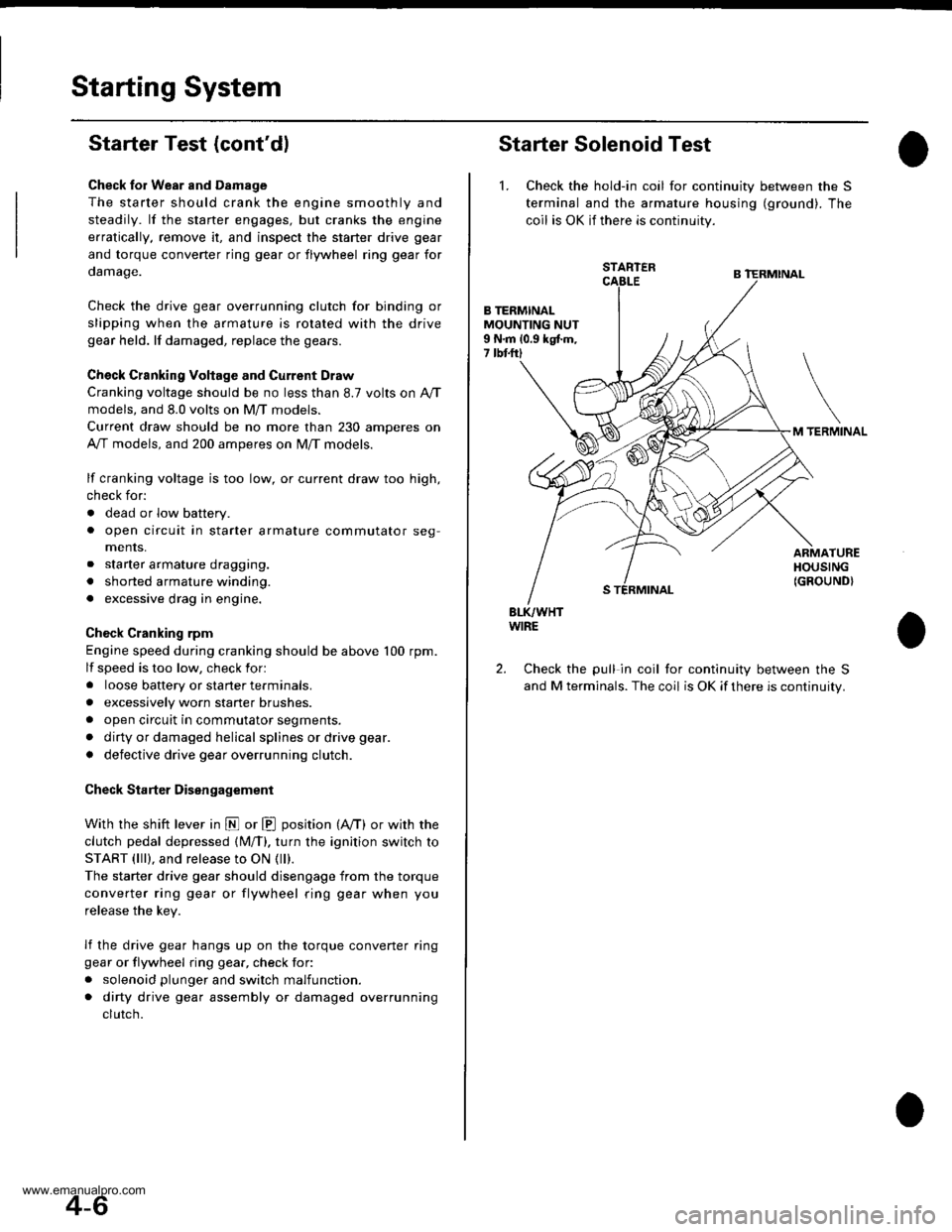
Starter Solenoid Test
1. Check the hold-in coil for continuity between the S
terminal and lhe armature housing (ground). The
coil is OK if there is continuity.
STARTER
B TERMINALMOUNTING NUT9 N.m 10.9 kgtm,7 tbtftl
TERMINAL
ARMATUREHOUSING(GROUND}
BLK/WHTWIRE
Check the pull in coil for continuity between the S
and M terminals. The coil is OK if there is continuity.
2.
4-6
www.emanualpro.com
Page 283 of 1395

Fuel Cut-off Control
. During deceleration with the throttle valve closed, current to the fuel injectors iscutoffto improvefuel economyat
speeds over 970 rpm ('97 - 98 models), 920 rpm ('99 - 00 modelsl.
. Fuel cut-off action also takes place when engine speed exceeds 6,500 rpm ('97 - 98 models), 6900 rpm ('99 - 00
models), regardless of the position of the throttle valve, to protect the engine from over-rewing.
With Ay'T model. the PCM cuts the fuel at engine speeds over 5,000 rpm when the vehicle is not moving.*'�
4,./C Comoressor Clutch Relav
When the ECM/PCM receives a demand for cooling from the air conditioning system, it delays the compressor from
being energized, and enriches the mixture to assure a smooth transition to the Ay'C mode.
Evaporative Emission (EVAP) Purge Control Solenoid Valve
When the engine coolant temperature is above 154"F (68'C), the ECM/PCM controls the EVAP purge control solenoid
valve which controls vacuum to the EVAP purge control canister,
Alternator Control
The system controls the voltage generated at the alternator in accordance with the electrical load and driving mode.
which reduces the engine load to improve the fuel economy.
PCM Fail-saf e/Back-up Functions
1. Fail-safe Function
When an abnormality occurs in a signal from a sensor, the ECM/PCM ignores that signal and assumes a pre-pre
grammed value for that sensor that allows the engine to continue to run.
2. Back-up Function
When an abnormality occurs in the ECM/PCM itself, the fuel injectors are controlled by a back-up circuit independent
of the system in order to permit minimal driving.
3. Self-diagnosis Function IMalfunction Indicator Lamp (MlL)l
When an abnormality occurs in a signal from a sensor, the ECM/PCM supplies ground for the MIL and stores the DTC
in erasable memory. When the ignition is initially turned on {ll), the ECM/PCM supplies ground for the MIL for two
seconds to check the MIL bulb condition.
4. Two Trio Detection Method
To prevent false indications, the Two Trip Detection Method is used for the HO2S*1, fuel metering-related. idle control
system, ECT sensor and EVAP control system self-diagnostic functions. When an abnormality occurs, the ECM/PCM
stores it in its memory. When the same abnormality recurs after the ignition switch is turned OFF and ON (ll) again,
the ECM/PCM informs the driver by lighting the MlL. However, to ease troubleshooting, this function is cancelled
when you jump the service check connector, The MIL will then blink immediately when an abnormality occurs.
5. Two (or Three) Driving Cycle Detection Method {'97 model)
A "Driving Cycle" consists of starting the engine, beginning closed loop operation, and stopping the engine. lf misfir-
ing that increases emissions or EVAP control system malfunction is detected during two consecutive driving cycles.
or TWC deterioration is detected during three consecutive driving cycles, the ECM/PCM turns the MIL on. However, to
ease troubleshooting, this function is cancelled when you jump the service check connector. The MIL will then blink
immediately when an abnormality occurs.
*1: '97 - 98 models*2: '99 - 00 models
5.
www.emanualpro.com
Page 354 of 1395

ldle Control System
ldle Air Control llAC) Valve
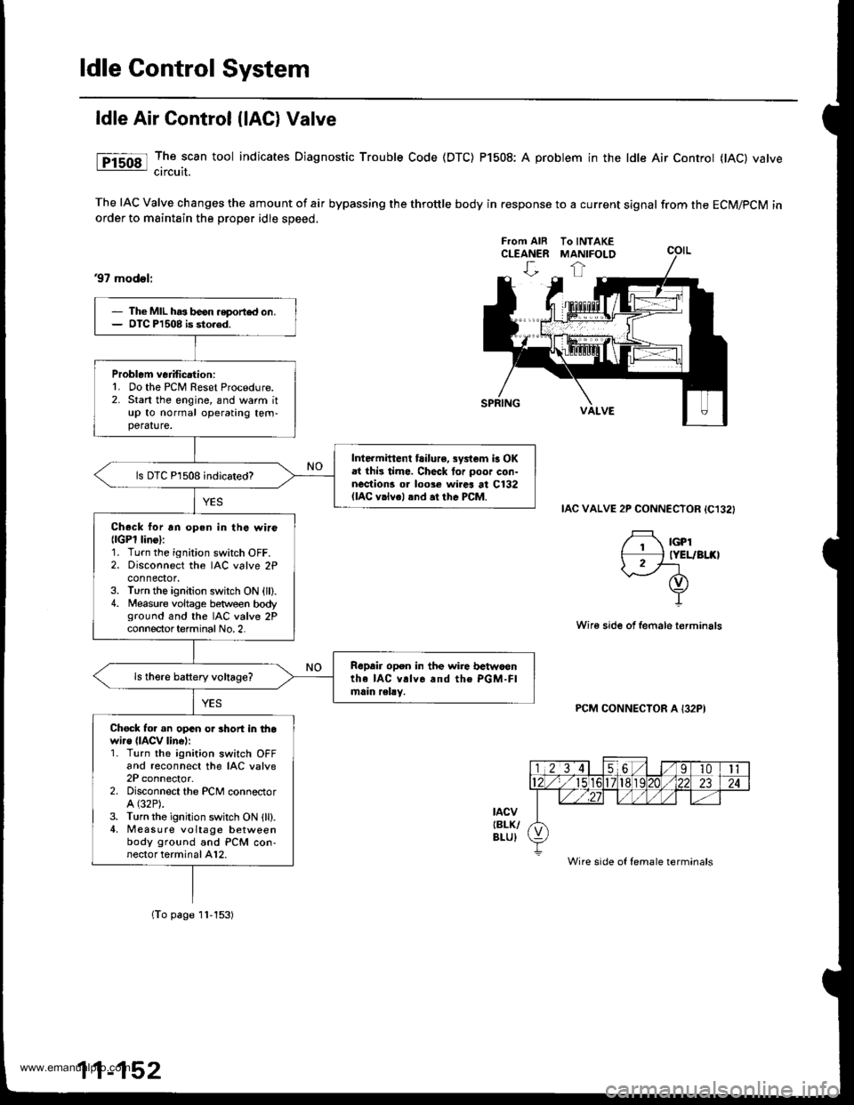
The scan tool indicates Diagnostic Trouble Code (DTC) Pl508: A probtem in the ldle Air Controt flAC) varvecircuit.
The IAC Valve changes the amount of air bypassing the throttle body in response to a current signal from the ECM/PCM inorder to maintain the proper idle speed.
37 model;
IAC VALVE 2P CONNECTOR {C132}
,f rcp'# IYEL/BI.(II2f-1-d)
Y
Wir€ side of female terminals
PCM CONNECTOR A I32PI
tacvIBLK/BLU)
From AIR To INTAKECLEANER MANIFOLD
Wire side of female terminals
The MIL has beon .eport€d on.OIC Pl508 is sto.ed.
Problem veiification:1. Do the PCM Reset Procedure.2. Start the engine, and warm itup to normal operating tem-perature.
Inte.mittent failure, systcm b OKat thi3 time. Check tor poo. con-nections or loose wircs at C132(lAC v.lvel and at the PCM.
ls DTC Pl508 indicated?
Check lor an open in the wir6{lGPl lins}:1. Turn the ignition switch OFF.2. Disconnect the IAC valve 2Pconnector.3. Turn the ignition switch ON {ll).4. Measure voltage between bodyground and the IAC valve 2Pconnector term inal No.2.
Repair open in the wire trctwoontha IAC v!lv6 and the PGM-Flmain relly.
Chock for an opan o. short in thowi.e (lACv linel:1. Turn the ignition switch OFFand reconnect the IAC valve2P connector.2. Disconnect the PCM conneclorA (32P).
3. Turn the ignition switch ON {ll).4, Measure voltage betweenbody ground and PCM con-nector terminal A12.
{To page 1l-153)
www.emanualpro.com
Page 1165 of 1395

Five-step Troubleshooting
1.
3.
Verify The Complaint
Turn on all the components in the problem circuit to
verify the customer complaint. Note the symptoms.
Do not begin disassembly or testing until you have
narrowed down the problem area.
Analyze The Schematic
Look up the schematic for the problem circuit.
Determine how the circuit is supposed to work by
tracing the current paths from the power feed
through the circuit components to ground. lf several
circuits fail at the same time, the fuse or ground is a
likely cause,
Based on the symptoms and your understanding of
the circuit operation, identify one or more possible
causes of the problem.
lsolate The Problem By Testing The Circuit
Make circuit tests to check the diagnosis you made
in step 2. Keep jn mind that a logical, simple proce-
dure is the key to efficient troubleshooting. Test for
the most likely cause of failure first. Try to make
tests at points that are easily accessible,
Fix The Problem
Once the specific problem is identified, make the
repair. Be sure to use proper tools and safe proce-
dures.
Make Sure The Circuit Works
Turn on all components in the repaired circuit in all
modes to make sure you've fixed the entire prob-
lem. lf the problem was a blown fuse, be sure to
test all of the circuits on the fuse. lvlake sure no new
problems turn up and the original problem does nol
recur.
4.
O
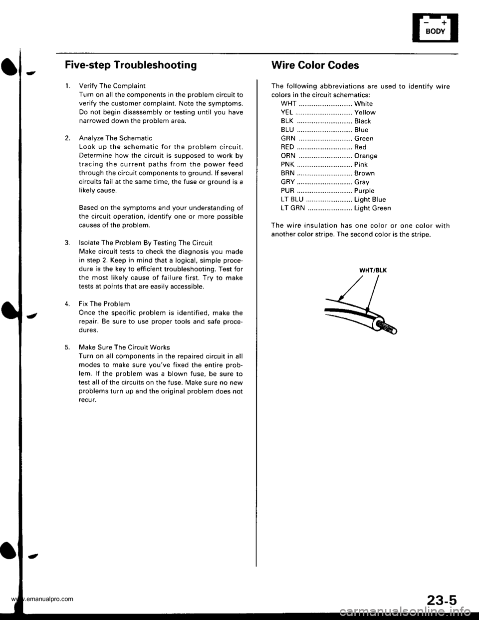
Wire Color Codes
The following abbreviations are used to identify wire
colors in the circuit schematics:
WHT ............................. White
YEL,.............................. Yellow
BLK ..........,................... Black
BLU .............................. Blue
GRN .............................Green
RED .............................. Red
ORN .............................Oran9e
PNK.....,........................ Pink
BRN .............................. Brown
GRY .............................. Gray
PUR .........,.................... Purple
LT BLU ..................,...... Light Blue
LT GRN ........................ Light Green
The wire insulation has one color or one color with
another color stripe. The second color is the stripe.
WHT/BLK
www.emanualpro.com