engine diagram HONDA CR-V 1999 RD1-RD3 / 1.G Workshop Manual
[x] Cancel search | Manufacturer: HONDA, Model Year: 1999, Model line: CR-V, Model: HONDA CR-V 1999 RD1-RD3 / 1.GPages: 1395, PDF Size: 35.62 MB
Page 16 of 1395

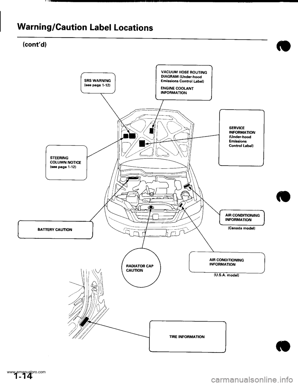
Warning/Caution Label Locations
(cont'd)
VACUUM HOSE ROUTINGDIAGRAM lUndor-hoodEmissions Control Lrb6ll
ENGINE COOLANTINFORMATION
SERVICEINFORMANON
{Under-hoodEmission3Control l.rbell
STEERINGCOLUMN NOTICE(s€e page 1-12)
RAOIATOR CAPCAUTION
AIR CONDITIONINGINFORMATION
(Canada model)
1-14
www.emanualpro.com
Page 17 of 1395
![HONDA CR-V 1999 RD1-RD3 / 1.G Workshop Manual
Under-hood Emissions Control Label
Emission Group ldentification
(1997 modell
Example:
VACUUM HOSE ROUTING DIAGRAM
LOADED IM TEST]NG OF PERMANENT fOUB WHEEL OSVE OR TRACT ON CONTROLEOLJIPPEDVEHTCLES HONDA CR-V 1999 RD1-RD3 / 1.G Workshop Manual
Under-hood Emissions Control Label
Emission Group ldentification
(1997 modell
Example:
VACUUM HOSE ROUTING DIAGRAM
LOADED IM TEST]NG OF PERMANENT fOUB WHEEL OSVE OR TRACT ON CONTROLEOLJIPPEDVEHTCLES](/img/13/5778/w960_5778-16.png)
Under-hood Emissions Control Label
Emission Group ldentification
(1997 modell
Example:
VACUUM HOSE ROUTING DIAGRAM
LOADED IM TEST]NG OF PERMANENT fOUB WHEEL OSVE OR TRACT ON CONTROL'EOLJIPPEDVEHTCLES MUST BE CONDUCTED ON A IOUR WHEEL DR VE SPEEO SYNCHRON ZED
ANON LOADEDTESTPBO(EOUBEMUSIBEPERFORMEO
50ST (50 Statesl:
THIS VEHICLE CONFOBMS TO U.S. EPA AND STATE OF
CALIFORNIA REGULATIONS APPLICABLE TO 1997
MODEL YEAR NEW LIGHT DUTY TRUCKS.
49ST {49 Statos/Federall:
THIS VEHICLE CONFORMS TO U.S. EPA REGULATIONS
APPLICABLE TO 1997 IVIODEL YEAR NEW LIGHT DUTY
TRUCKS.
CAL (Calitornial:
THIS VEHICLE CONFORMS TO U.S. EPA AND STATE OF
CALIFORN IA REGULATIONS APPLICABLE TO '1997
MODEL YEAR NEW TLEV LIGHT DUTY TRUCKS
PROVIDED THAT THIS VEHICLE IS ONLY INTRODUCED
INTO COMMERCE FOR SALE IN THE STATE OF
CALIFORNIA.
Ii/PORTANT VEHICLE INFORIMATIONENGINE FAMILY VHN2 OIJCrcKDISPIACEMENT'2 OLITEREVAPORAT VE f AM]LY VNNl0778YMBP
CATALYSTREfERTOSEBVICEMANUALfORAODITIONAL NFORMATON.TUNT I-]P CONDITIONSENGINE AT NORI\,!AL OPERATNG TEMPERATURE,ALLACCESSOR ES TL]RNED OFF COOLING FAN OIFTRANSM1SSION NNEUTRALNO OTHEB ADJUSTMENIS NEEDED
ap' | \6( Zror '. ND \. 61F L r
TNIS VENICLE CONFORMS TO U.S EPA REGUI.ATIONSAPPI CASLE TO I99] MODET YEAR N€W L GNI DUTY TRACKS
@
Engine Family: vHN2.o l JGKE
Engine and Evaporative Families
T_fT
Model Year I Iv:1s97 | LManufaqturer iHN: Honda I
Displacement
Class
1: Light Duty Vehicle
Fuol Systom ,nd Numb€r of valves
J: Electronic Sequential Multiport
Injection (three or more valves per
cylinder)
Fuel Type
G: Gasoline
Standard
F: 49 or 50 States Tier 1
K: 49 or 50 States Tier 1
1: California Tier 1
2: California TLEV
3: California LEV
4: California ULEV
"r0", "*,
T|
V: 1997
Manufacturer
HN: Honda
Catalyst
E, F, G, H: Three Way Catalyst
OBD
K - T: OBD Equipped
Evaporative Family:
Storago System
1: Canister
Canistor Working Capacity (gramsl
Canister Conf igulation
A: Plastic Housing (Closed Bottom)
B: Plastic Housing (OPen Bottom)
Fusl System
Y: Fuel Injection
FuelTank
M: Metal
Standard
A: Current Evap
B: Enhanced Evap
Wild C.rd
VHNlOTTBYMBP
1-1 5
www.emanualpro.com
Page 51 of 1395

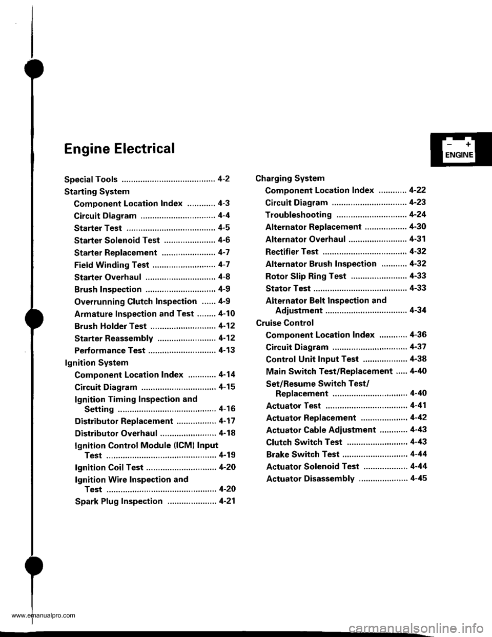
Engine Electrical
Speciaf Tools ............. 4-2
Starting System
Component Location Index ............ 4-3
Circuit Diagram ................................ 4-4
Starter Test ........... 4-5
Starter Solenoid Test ...................... 4'5
Starter Replacement ....................... 4-7
Field Winding Test ........................... 4-7
Starter Overhaul ............................,. 4-8
Brush Inspection ...........................,., 4-9
Overrunning Glutch Inspection ...... 4-9
Armature lnspection and Test ........4-10
Brush Holder Test ............................ 4-12
Starter Reassemb|y ......................... 4-1 2
Perf ormance Test ............................. 4- 1 3
lgnition System
Component Location Index ............ 4-14
Circuit Diagram ................................ 4-15
lgnition Timing Inspection and
Setting .......................................... 4-16
Distributor Replacement ........,........ 4-17
Distributor Overhaul .............,,......... 4-18
lgnition Control Module (lCM) Input
Test ..............................,................ 4-19
fgnition Coil Test .............................. 4-2O
lgnition Wire Inspection and
Test ............................................... 4-20
Spark Plug Inspection ..................... 4-21
-+
ENGINE
Charging System
Component Location Index ............ 4-22
Circuit Diagram ....................,........... 4-23
Troubleshooting .............................. 4-24
Alternator Replacement ..........,....... 4-30
Alternator Overhaul .......,,................ 4-31
Rectifier Test .........4-32
Alternator Brush Inspection ........... 4-32
Rotor Slip Ring Test ........................ 4-33
Stator Test ............. 4-33
Alternator Belt Inspection and
Adiustment ........4-34
Gruise Control
Component Location Index .,,,........ 4-36
Circuit Diagram ................................ 4-37
Control Unit Input Test ................... 4-38
Main Switch Test/Replacement ..... 4-40
Set/Resume Switch Test/
Replacement .......................,........ 4'40
Actuator Test ....,,., 4-41
Actuator Replacement ...............,.... 4-42
Actuator Cable Adiustment ............ 4-43
Clutch Switch Test .......................... 4-43
Brake Switch Test .................. .......... 4-44
Actuator Solenoid Test .............. ...,. 4-44
Actuator Disassembly ..................... 4-45
www.emanualpro.com
Page 189 of 1395

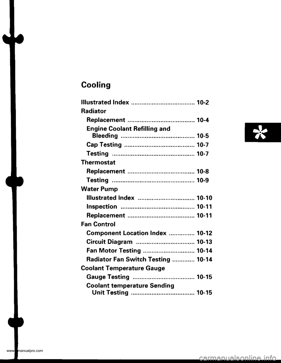
Cooling
f ffustrated Index ........... ..... 1O-2
Radiator
Rep|acement ...........,....,...................... 10-4
Engine Coolant Refilling and
Bleeding ..,.,................. 10-5
Cap Testing .................... 10-7
Testing ......10-7
Thermostat
Rep|acement ....................................... 10-8
Testing ...... 10-9
Water Pump
lllustrated lndex ....,..... .. 10-10
Inspection . 10-1 1
Replacement ....................................,.. 10-1 1
Fan Gontrol
Component Location Index ............... 10-12
Circuit Diagram ............. 10-13
Fan Motor Testing ......... 10-14
Radiator Fan Switch Testing ............. 10-14
Coolant Temperature Gauge
Gauge Testing ............... 10-15
Coolant temperature Sending
Unit Testing ........,....... 10-15
www.emanualpro.com
Page 1161 of 1395

Body Electrical
Speciaf Toofs ,...,..,.............-.23-2
Troubleshooting
Tips and Precautions ......,.,..........,.................. 23-3
Five-step Troubleshooting ........,.,.,...,,.,......... 23-5
Wire Color Codes ...,....,.. 23-5
Relay and Control Unit Locations
Engine Compartment ..,.,......,......................... 23-6
Dashboard ,.,.,..............-.- 23-7
Door ....................... .........23-10
Index to Cilcuits and Sysiems
Accessory Socket .. ,....,.,..,.,. 23-95*Airbags ................ .,....,. Sestion 24
Air Conditioning ,.,.,.... Section 22
Alternator ................... Section 4
Anti-lock Brake System {ABSI ................... Section 19'A/T Gear Position Indicator ....................... Section 1,1
Automatic Transmission System ...........,.. Section 14
Battery ................... ..............23-50
Blower Controls .,...,.,, Section 22
Charging System ....... Seqtion il
Clock -'98 Model ................ 23-98
Connector ldentification and Wire HarnessRouting .................. ......... 23.11
Cruise Control ............ Ssction 4
Dash Lights Brightness Contlo||er ..................... 23-90
Fan Conlrols ...,......,.... Section 10
Fuel Pump ,..,.,...,....,.... Section 11
Fuses...................... .,,.,.,.,.,,.,23-40*Gauges
Circuit Diagram ......-....-..23-58
Fuel Gauge .....,.,..... Section 11
Speedometer ..,..........,... 23-56
Ground Distribution ,....,.,...23-46
Hatch Glsss ODenor .........................,.,.,.,.,..,.,.,.,,. 23-121
Heater Controls .-........ Soction 21*Horns.,...,..,.,.,....... ................23"104*fgnition Switch ,,.,.,..,.,.,,.,.,.,23-51
lgnition Key Light System -'97 Mod6l .............. 23.88
-+
BODY
www.emanualpro.com