front wheels suspension HONDA CR-V 1999 RD1-RD3 / 1.G Workshop Manual
[x] Cancel search | Manufacturer: HONDA, Model Year: 1999, Model line: CR-V, Model: HONDA CR-V 1999 RD1-RD3 / 1.GPages: 1395, PDF Size: 35.62 MB
Page 21 of 1395

Lift and Support Points
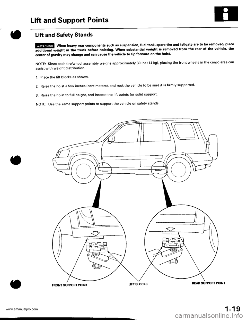
Lift and Safety Stands
ffi When heaw rear components such as suspension, Iuel tank, spare tire and tailgate are to b€ lemoved, place
!iiii-'rn"t r""igtrt in the trunk before hoisting. When substantial weight is removed flom the lear ot the vehicle, the
center of gravity may change and can cause the vehicle to tip fotward on the hoist'
NOTE: Since each tire/wheel assembly weighs approximately 30 lbs (14 kg), placing the front wheels in the cargo area can
assist with weight distribution.
1. Place the lift blocks as shown.
2. Raise the hoist a few inches (centimeters), and rock the vehicle to be sure it is firmly supported.
3. Raise the hoist to full height, and inspect the lift points for solid support'
NOTE: Use the same suppon points to support the vehicle on safety stands'
LIFT BLOCKSREAR SUPPORT POIMTFRONT SUPPORT POINT
1-19
www.emanualpro.com
Page 23 of 1395

Towing
lf the vehicle needs to be towed, call a professional
towing service. Never tow the vehicle behind another
vehjcle with just a rope or chain. lt is very dangerous.
Emergency Towing
There are three popular methods of towing a vehicle.
Flat-bed Equipment - The operator loads the vehicle on
the back of a truck. This is the best way of transporting the
vehicle.
Wheel Lift Equipment - The tow truck uses tlvo pivoting
arms that go under the tires lfront or rear) and lifts them
off the ground. The other two tires remain on the
ground. The vehicle's suspension and body can be
seriously damaged if this method of towing is attempted.
Sling-type Equipment - The tow truck uses metal cables
with hooks on the ends. These hooks go around parts of
the frame or suspension and the cables lift that end of
the vehicle off the ground. The vehicle's suspension and
body can be seriously damaged if thjs method of towing
is attempted. This methed of towing the CR-V is
unaccePtable.
The onlv recommended way of towing the CR-V is on a
flat-bed truck. Two wheel drive CR-V's may also be
towed with all four wheels on the ground.
Towing the four-wheel dlive CR-v with only two
wheels on the ground will damage parts of the 4wD
system. It this vehicle is damaged, it should be towed
on a flat-bed truck ol trailel.
It the 2 wheel drive CR-v is towed wiih all tour wheels
on the ground, do the following:
Manual Transmission
. Release the parking brake.
. Shift the transmission in Neutral
Automatic Transmission
. Release the parking brake.
. Sta rt the engine.
. Shift to lD.l position. then E position.
. Turn off the engine.
lmproper towing preparation will damage the
transmission. Follow the above procedure exactly. lf
you cannot shift the transmission or start the engine,
the vehicle must be transported on a flat-bed truck.
lf the vchicle is towed with four wheels on the ground,
il is best to tow the vehicle no larther than 50 miles (80
km), and keep the speed below 35 mph {55 km/h).
Trying to lift or tow the vehicle by ihe bumpers will
cause serious damage. The bumpers ale not dosigned
to support the vehicle's weight.
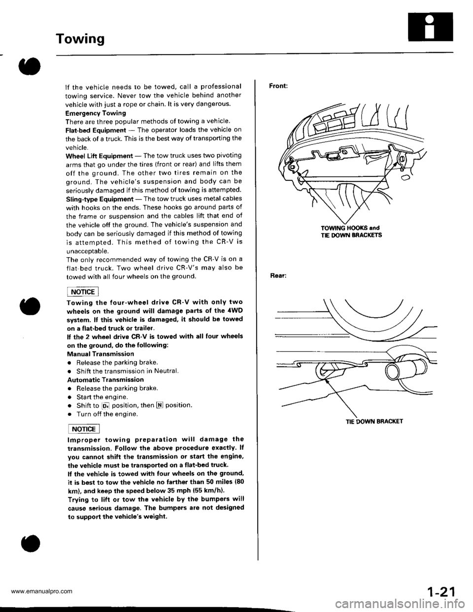
Front:
Rear:
lOwlNG HOOKS .ndTIE DOWN BRACKETS
TIE DOWN BRACKET
1-21
www.emanualpro.com
Page 902 of 1395

Wheel Alignment
Caster
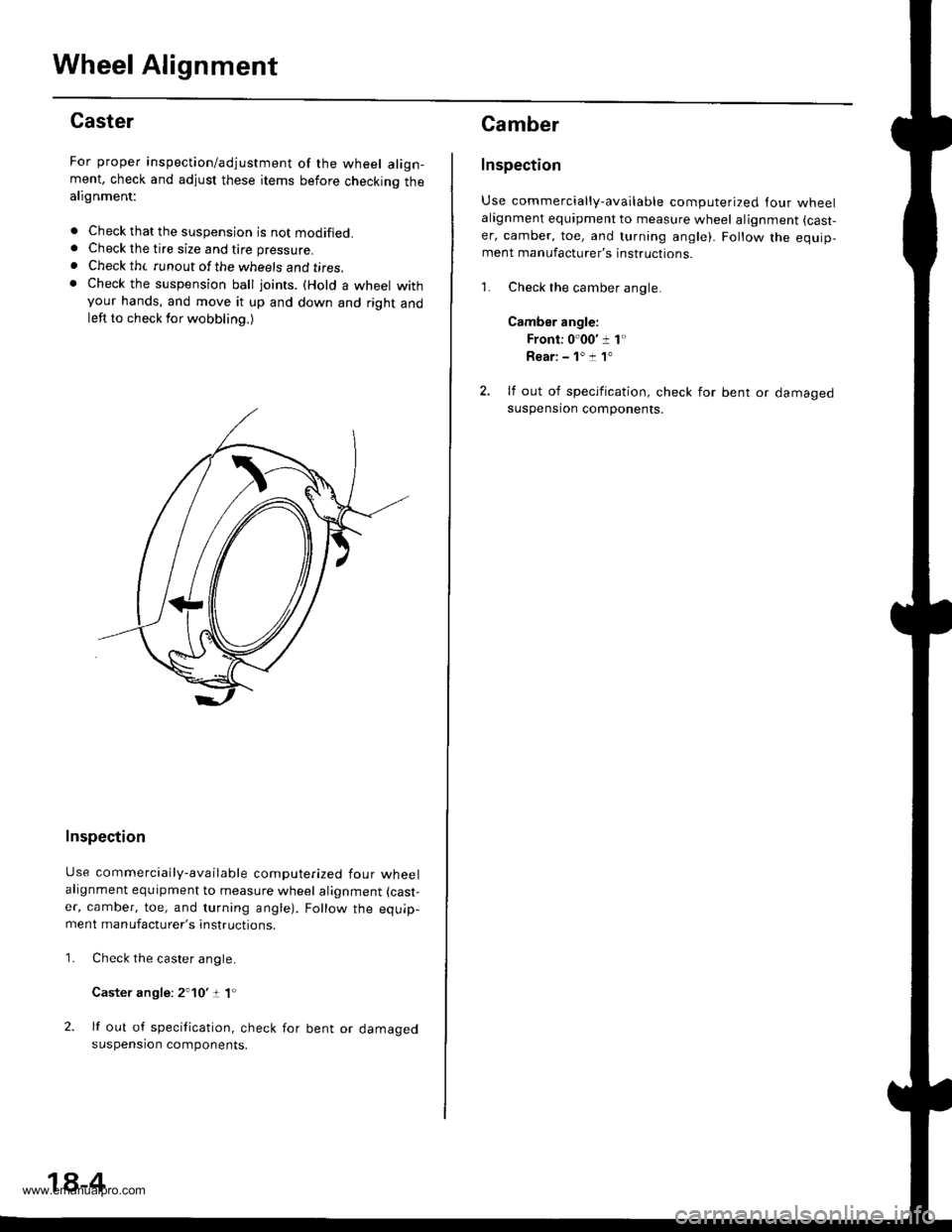
For proper inspection/adjustment of the wheel align-ment, check and adjust these items before checkinq thealignment:
. Check that the suspension is not modified.. Check the tire size and tire pressure.
. Check th( runout of the wheels and t;res,. Check the suspension ball joints. (Hold a wheel withyour hands, and move it up and down and right andleft to check for wobbling.)
Inspection
Use commercially-available computerized four wheelalignment equipment to measure wheel alignment (cast-
er, camber, toe, and turning angle). Follow the equip-ment manufacturer's instructions.
Check the caster angle.
Caster angle: 2'10':t 1"
lf out of specification, check for bent or damagedsuspension components.
1.
18-4
Camber
Inspection
Use commercially-available computerized lour wheelalagnment equipment to measure wheel alignment (cast,
er, camber, toe, and turning angle). Follow the equip,ment manufacturer's instructions.
1. Check the camber angle.
Camber angle:
Front: 0'00' 1 1"
Rear: - 1' :! 1"
2. lf out of specification, check for bent or damagedsuspensron components.
www.emanualpro.com
Page 914 of 1395

Front SuspensionFront Damper
Ball Joint Boot Replacement
1.
BALL PIT{ TAPEFEO S€CTION
B{rcY HSISECTIO BOOT |NSTSECTIONwip6 off tho gr6aso.Wipo otf th6 grors€.
Wipe the grease off the sliding surface of the ball
pin, and pack it with fresh greass. Keep grease off
the boot installation section and the taoered section
of the ball pin.
Do not allow dust, dirt, or other foreign materials to
enter the boot.
Install the boot in the groove of the boot installation
section securelv, then bleed air.
Install the upper and lower ball joint boot set rings
using the special tools as follows:
Lower ball joint: Adjust the special tool with the
adjusting bolt until the end of the tool aligns with
the groove on the boot. Slide the set ring over the
tool and into oosition.
Upper ball joint: Hold the tool over the ball joint,
then slide the set ring over the tool and into position.
EAII JOINTAD'USN G BOLTAdjust th6 depth byturning the bolt.
Remove the set ring and the boot.
Pack the interior of the boot and lip with grease. Do
not contaminate the boot installation section with
grease.
B(X)T CUPGUttrE
UPPER BAI.IJott'tr Boor:07GAG - SO407q)LOWEF BATIJOIIYI EOOTI0t97il - SA507lXl
After installing the boot, check the ball pin tapered
section for grease contamination, and wipe it if nec-gssary.
18-16
Removal
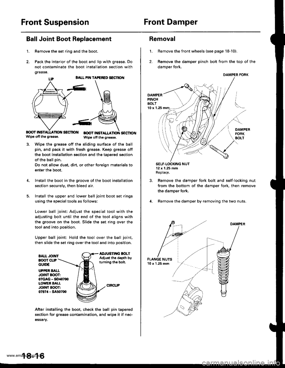
1, Remove the front wheels (see page 18-10).
2. Remove the damper pinch bolt from the top of the
damper fork.
DAMPERPINCHBOLT'10 x 1.25
SELF.LOCKING NUT12x 1.25 fifiReplace.
Remove the damper fork bolt and self-locking nut
from the bottom of the damper fork, then remove
the damper fork.
Remove the damper by removing the two nuts.
DAMPER
DAMPER FORK
www.emanualpro.com