horn HONDA CR-V 1999 RD1-RD3 / 1.G Workshop Manual
[x] Cancel search | Manufacturer: HONDA, Model Year: 1999, Model line: CR-V, Model: HONDA CR-V 1999 RD1-RD3 / 1.GPages: 1395, PDF Size: 35.62 MB
Page 77 of 1395
R'oR
l
u
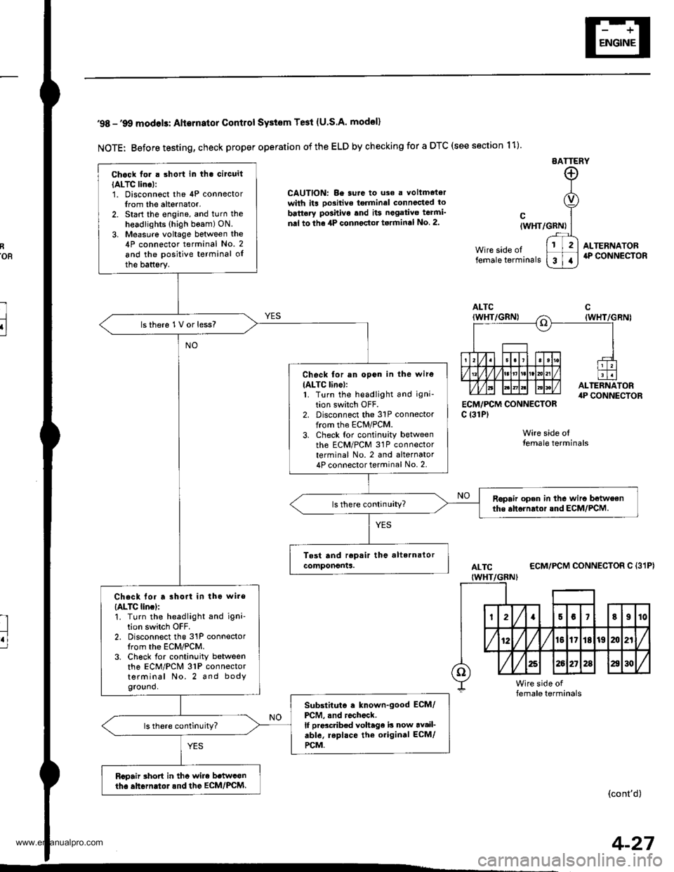
'98 -'9O modols: Alternator Contlol SYstem Te3t (U.S.A' model)
NOTE: Before testing, check proper operation of the ELD by checking for a DTC (see section 11)
EATTERY
CAUTION: Be surc to uso a voltmetorwith its oo3itive torminel connccted to
battery po3hivo tnd its negativo teami'
nal to the 4P connector torminal No 2.
ECM,/PCM CONNECTORc {31P)
Wire side olfemale terminals
cIWHT/GRN)
Wire side oltemale terminals
ALTERNATOR4P CONNECTOR
ALTC
IWHT/GBNI
ECM/PCM CONNECTOR C {31P}
(cont'd)
Chock tor . short in tha circuit
IALTC lino):1. Disconnoct the 4P connectorIrom the alternator.2. Start the engine, and turn the
headlights (high beam) ON.
3. Measure voltage between the4P connector terminal No. 2
and the positive terminal oIthe battsry.
lsthere 1V or less?
Check for an opon in the wire
IALTC line):1. Turn the headlight and igni-
tion switch OFF.2. Disconnect the 31P connectorfrom the ECM/PCM.3. Check tor continuity betweenth6 ECM/PCM 31P connectorterminal No. 2 and alternator4P connector terminal No. 2.
Ropair open in the wiro betweenthe ahornrtor and ECM/PCM.
Chack lor a rhort in tho wire
{ALTC lincl:'!. Turn the headlight and igni'tion switch OFF.2. Disconnect the 31P connectorIrom the ECM/PCM.3. Ch6ck for continuity betweenthe ECM/PCM 31P connectorterminal No. 2 and bodyground.
Substituto . known-good ECM/
PCM, .nd rochock.lf prdcdb€d voltage b now av.il-able, repl.ce the original ECM/
rcM.
Rcpair rhort in thc wire b.twconth. ahGrn.tol.nd the EcM/PcM.
4-27
www.emanualpro.com
Page 79 of 1395
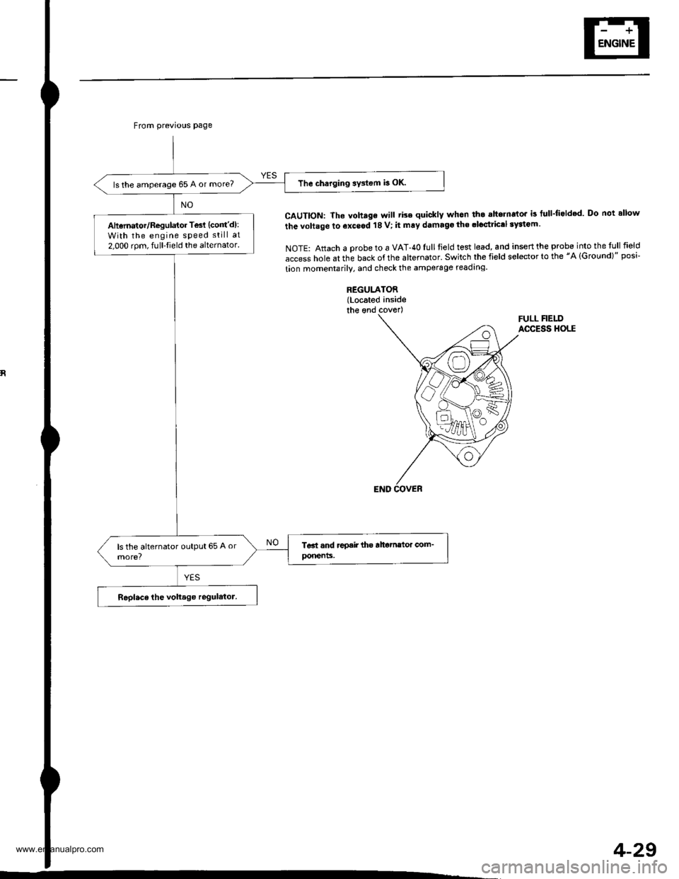
From previous page
The charging sy3tem b OK.ls the amperage 65 A or more?
Aharnator/Regulator Tesl (cont'd):
With the engine speed still at
2.000 rom, fulllield the alternator.
CAUTION: The voh.ge will tise quickly whon th. ahornato. is tull-li.lded Do not allow
the voltage to exceod 18 V; it mry damago the .loctrictl 3yaiGm.
NOTE: Attach a probe to a VAT-40Iull tield test lead, and inseft the probe into the tull field
access hole at the back of the altemator' Switch the field selector to the "A lGround)" posi-
tion momentarily. and check the amperage readrng.
REGULATOR(Located insidethe ond coverlFULL FIELDACCESS HOLE
4-29
www.emanualpro.com
Page 89 of 1395

Disconnest the lilP connector from the control unit.
Csvity WireTest condition
R€conn€ct tho 14P connGctor to the control unit.
Test: Desired resultPossible cause it result is not obtained
BRNAr'VHTUnder all conditionsCheck for resistance to groundl
There should be 80 - 120 o.
Faulty actuator solenoid
Poor ground (G202)
An open in the wire1BRNUnder all conditionsCheck for resistance to groundl
There should be 40 - 60 0.
11BRN/BLKUnder all conditionsCheck for resistance to ground:
There should be 70 - 110 O.
2GRY
lgnition switch ON (ll),
main switch ON and
brake pedal depressed,
then released
Check for voltage to ground:
There should be 0 V with the pedal
depressed and battery voltage with
the pedal released.
. Faulty brake switch. An open in the wire
BLKUnder all conditionsCheck for continuity to ground:
There should be continuity.
. Poor ground (G401). An open in the wire
5GRNMHT
Brake pedal depressed,
then released
Check for voltage to ground:
There should be battery voltage with
the pedal depressed, and 0 V with
the pedal released.
Blown No.52 1'15 Alfuse in the
under-hood fuse/relay box
Faulty brake switch
An open in the wire
LT GRN/
RED
Set button pushedCheck for voltage to ground:
There should be battery voltage.Blown No. 52 {'15 A} fuse in the
under-hood fuse/relay box
Faulty horn relay
Faulty sevresume switch
Faulty cable reel
An open in the wire7LT GRN/
BLK
Resume button pushed
10RED/BLU
lgnition switch ON lll)Attach to ground:
Cruise indicator light in the gauge
assembly should come on.
Elown bulbBlown No. 25 (7.5 A) tuse in theunder-dash fuse/relay box
Faulty dimming circuit in the gauge
assembly
An open in the wire
ELU^r'r'HT
lgnitjon switch ON {ll}and main switch ON;
raise the front of the
vehicle, block one wheel
and rotate the other
wheel slowly.
Check for voltage between the
ELUA/VHT @ and BLK O terminalsl
There should be 0 - 5 V or more-0 - 5 V or more repeatedly.
Faulty vehicle speed sensor (VSS)
An open in the wire
r3LT GRN
lgnition switch ON {ll}and main switch ONCheck for voltage to ground:
There should be battery voltage.
Blown No. 14 (7.5 A) fuse in theunder-dash fuse/relay box
Faulty main switch
An open in the wire
l4PNK
A'/T: Shift lever in E, EotE
lvl/T: Clutch pedal
releaseo
Check for continuity to ground:
There should be continuity.NOTE: There should be no continu-
ity when the shift lever is in otherpositions or when the clutch pedal is
oepresseo.
Faulty A/f gear position switch 1A,/TlFaulty or misadjusted clutch switch
fi{/r)Poor ground (G101)
An open in the wire
BLU
Start tho engine. turnthe main switch ON, anddrive the vehicle over 25
mph (40 km/h)with the
crurse control set
Check for voltage to ground:
There should be approx.5 V
. Faulty cruise control unit. Shod to ground
*: '98 - 00 models with Automatic Transmission.
4-39
www.emanualpro.com
Page 368 of 1395
ldle Control System
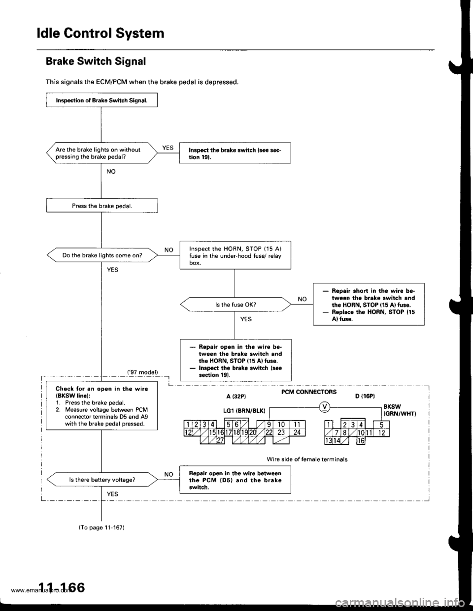
Brake Switch Signal
This signals the ECM/PCM when the brake pedal is depressed.
('97 model)'- - - - -_- Il
PCM CONNECTORSa t32P) D ll6Pl
BKSW(GRN/WHT)
Wire side of female terminals
Insp€ction of Brak. Switch Signal.
Are the brake lights on withoutpressing the brake pedal?
Inspect the HORN, STOP {15 A)fuse in the undeFhood luse/ relaybox.Do the brake lights come on?
Reoair short in the wire be-tween th€ b.ake switch andth6 HoRN, STOP {15 A)luso,Replaco the HoRN, STOP (15
Al fuse.
Repair op6n in the wir€ be-tween the brake switch andtho HORN, STOP (15 Allus6.Inspect the brrke switch (see
aection l9l.
Check tol .n open in the wire{BXSW linel:1. Press the brake pedal.2. Measure voltage between rcMconnector terminais D5 and Agwith the brake pedal pressed.
Reprir open in the wire betweenthe PcM lD5l rnd the brakeswitch.
(To page 11-167)
1 1-166
www.emanualpro.com
Page 863 of 1395
Steering Wheel
Removal
SRS components are located in this area. Review the
SRS component locations, precautions, and procedures
in the SRS section (24) before performing repairs or ser-
vice.
1. Align the front wheels straight ahead. then remove
the driver's airbag assembly (see section 24) from
the steering wheel.
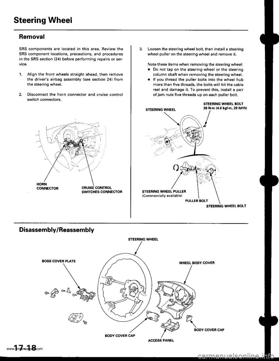
2. Disconnect the horn connector and cruise control
switch connectors.
CONTROLSWITCHES CONNECTOR
3. Loosen the steering wheel bolt, then install a steering
wheel puller on the steering wheel and remove it.
Note these items when removing the steering wheel:
. Do not tap on the steering wheel or the steering
column shaft when removing the steering wheel.
. lf you thread the puller bolts into the wheel hub
more than five threads, the bolts will hit the cable
reel and damage it. To prevent this, install a pair
of jam nuts five threads up on each puller bolt.
STEERING WHEEL BOLT39 N.m 14.0 kgt.m,29 lbtftl
STEERING WHEEL EOLT
Disassembly/Reassembly
EOSS COVER PLATE
_^M
STEERING WHEEL
WHEEL BODY COVER
17-18
@,
ACCESS PANEL
h"\
BODYCOVER CAP
www.emanualpro.com
Page 864 of 1395
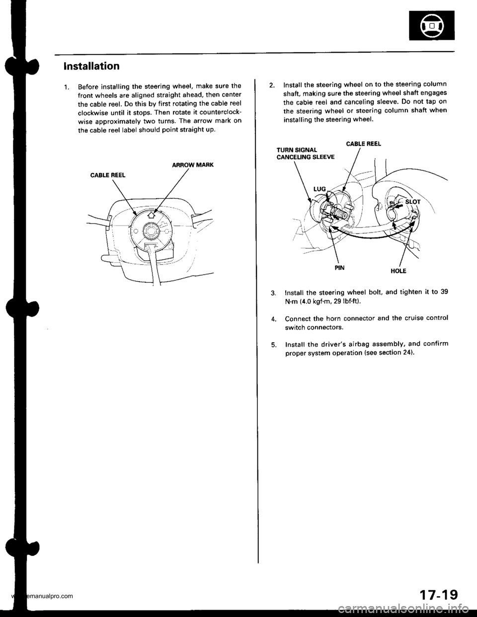
lnstallation
1. Before installing the steering wheel, make sure the
front wheels are aligned straight ahead, then center
the cable reel. Do this by first rotating the cable reel
clockwise until it stops. Then rotate it counterclock-
wise approximately two turns. The arrow mark on
the cable reel label should point straight up.
ARROW MARK
2. Install the steering wheel on to the steering column
shaft, making sure the steering wheel shaft engages
the cable reel and canceling sleeve. Do not tap on
the steering wheel or steering column shatt when
instailing the steering wheel
HOLE
Install the steering wheel bolt, and tighten it to 39
N.m (4.0 kgf.m, 29 lbf.ft).
Connect the horn connector and the cruise control
switch connectors,
Install the driver's airbag assembly, and confirm
proper system operation (see section 24).
CABLE REEL
17-19
www.emanualpro.com
Page 1161 of 1395

Body Electrical
Speciaf Toofs ,...,..,.............-.23-2
Troubleshooting
Tips and Precautions ......,.,..........,.................. 23-3
Five-step Troubleshooting ........,.,.,...,,.,......... 23-5
Wire Color Codes ...,....,.. 23-5
Relay and Control Unit Locations
Engine Compartment ..,.,......,......................... 23-6
Dashboard ,.,.,..............-.- 23-7
Door ....................... .........23-10
Index to Cilcuits and Sysiems
Accessory Socket .. ,....,.,..,.,. 23-95*Airbags ................ .,....,. Sestion 24
Air Conditioning ,.,.,.... Section 22
Alternator ................... Section 4
Anti-lock Brake System {ABSI ................... Section 19'A/T Gear Position Indicator ....................... Section 1,1
Automatic Transmission System ...........,.. Section 14
Battery ................... ..............23-50
Blower Controls .,...,.,, Section 22
Charging System ....... Seqtion il
Clock -'98 Model ................ 23-98
Connector ldentification and Wire HarnessRouting .................. ......... 23.11
Cruise Control ............ Ssction 4
Dash Lights Brightness Contlo||er ..................... 23-90
Fan Conlrols ...,......,.... Section 10
Fuel Pump ,..,.,...,....,.... Section 11
Fuses...................... .,,.,.,.,.,,.,23-40*Gauges
Circuit Diagram ......-....-..23-58
Fuel Gauge .....,.,..... Section 11
Speedometer ..,..........,... 23-56
Ground Distribution ,....,.,...23-46
Hatch Glsss ODenor .........................,.,.,.,.,..,.,.,.,,. 23-121
Heater Controls .-........ Soction 21*Horns.,...,..,.,.,....... ................23"104*fgnition Switch ,,.,.,..,.,.,,.,.,.,23-51
lgnition Key Light System -'97 Mod6l .............. 23.88
-+
BODY
www.emanualpro.com
Page 1169 of 1395
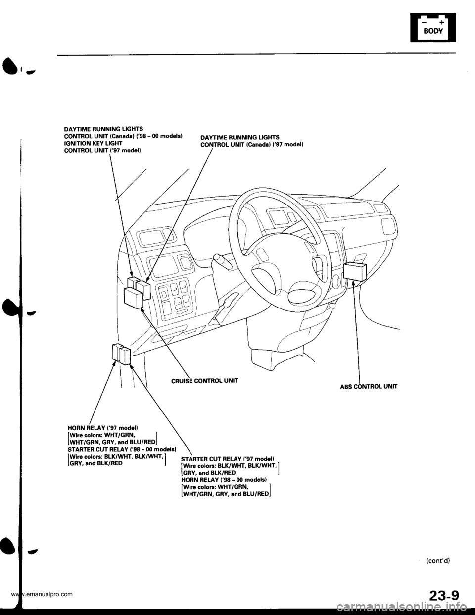
DAYTIME BUNNING LIGHTSCONTROL UNIT (Canrda) {'98 - (X) modok)IGNITION KEY LIGHTCONTROL UNIT l€7 model)
OAYTIME RUNNING LIGHTSCONTROL UNIT lcanad!l l'97 modell
CRUISE CONTNOL UNIT
HORN BELAY 137 modellIwiro color3: WHT/GRN, IIWHT/GBN, GRY, and BLU/REDI
IWir6 color3: BLK/WHT, BLK^ UHT,I
lGRY,.nd BLx/nED I
STARTER CUT RELAY {'98 - 00 modelsl
STARTEn CUT RELAY l€7 mod€ll
lwire colors: BLK/WHT, BLK/WHY,l
IGRY, and BLK/RED IHORN FELAY l'98 - 00 modcb)lwire coloF: WHT/GRN, lLWHT/GRN, GRY, and BLU/REDI
{cont'd)
23-9
www.emanualpro.com
Page 1176 of 1395
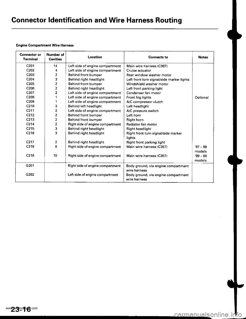
Gonnector ldentification and Wire Harness Routing
Engine Compartment Wire Harness
Connector ol
Terminal
Number of
CavitiesLocationConnects toNotes
c20'l
c202
c203
c204
c205
c206
c207
c208
c209
c210
c212
c213
c2't4
c215
c216
c217
c21A
c218
14
2
2
1'l
2
10
Left side of engine compartment
Left side of engine compartment
Behind front bumper
Behind right headlight
Behind front bumper
Behind right headlight
Left side of engine compartment
Left side of engine compartment
Left side of engine compartment
Behind left headlight
Left side of engine compartment
Behind front bumper
Behind front bumper
Right side of engine compartment
Behind right headlight
Behind right headlight
Behind right headlight
Right side of engine compartment
Right side of engine compadment
Main wire harness (C307)
Cruise actuator
Rear window washer motor
Left front turn signal/side marker lights
Windshield washer motor
Left front parking light
Condenser fan motor
Front fog lights
IVC compressor clutch
Left headlight
IVC pressure switch
Left horn
Right horn
Radiator fan motor
Right headlight
Right front turn signal/side marker
lights
Right front parking light
Main wire harness 1C357)
Main wire harness (C357)
Optional
'97 - 98
models'99 - 00
mooets
G201
G202
Right side of engine companment
Left side of engine compartment
Body ground, via engine compartment
wire harness
Body ground, via engine compartment
wire harness
23-16
www.emanualpro.com
Page 1180 of 1395

Connector ldentification and Wire Harness Routing
Main Wire Harn€ss (left side of dash and floor branchesl {cont,dl
c401
c402
c403
c404
c404
c405
c406
c407
c408
c409
c410
c410
c411
c412
c413
c413
c414
c415
c416
c416
c417
c418
c419
c420
c420
c421
c422
c423
c424
c425
c42A
c426
c437
c438
c438
c439
c440
c441c442
5
20
20
24
't4
8
5
3
12
10'1
18
20'18
10
15
1
4
8
5
5
22
Behind left kick panel
Behind left kick panel
Behind left kick panel
Behind left kick panel
Behind left kick panel
Under left side of dashUnder left side of dashUnder left side of dashUnder left side of dashUnder left side of dashUnder left side of dashUnder left side of dash
Under left side of dashUnder left side of dashUnder left side of dash
Under left side of dash
Under left side of dashUnder left side of dashUnder left side of dashUnder left side of dashUnder left side of dashUnder left side of dashUnder left side of dashUnder left side of dash
Under left side of dashUnder left side of dashUnder left side of dashUnder middle of dashUnder middle of dashUnder middle of dashUnder middle of dashUnder middle of dash
Under left side of dashUnder left side of dash
Under left side of dashUnder left side of dashUnder left side of dashUnder left side of dashUnder left side of dash
Under left side of dash
Under left side of dashUnder left side of dashUnder left side of dashUnder left side of dash
Starter cut relay
Horn relay
Left side wire harness (C558)
Left side wire harness (C559)
Left side wire harness (C559)
Cruise control unitDaytime running lights control unitDaytime running lights control unitlgnition key light control unitInterior wire harness {C701)Cable reel
Cable reel
lgnition key switchlgnition key switch
Combination switch sub-harness {C753)
Combination switch sub-harness (C753)
SRS main harness (C803)
Dashboard wire harness (C503)
Dashboard wire harness (C501)
Dashboard wire harness {C501)Under-dash fuse/relay box (C922)
Under-dash fuse/relay box (C920)
Under-dash fuse/relay box (C919)
lntegrated control unit
Integrated control unitFront fog lights switchBrake switch
Interlock control unitReverse relay
Rear accessory socket relayRear accessory socket relayRear heated oxygen sensor sub-harness (C722)
Security control unitSecurity starter cut relay (for securityalarm system)
Junction connector (for interlock system)Security wire harnessSecurity wire harnessRear window wiper control unitCombination switch sub-harness (C760)
Combination switch sub-harness (C760)
Securlty indicatorSecurity valet switchClutch interlock switchClutch switch (for cruise control)
'97 model'98 - 00mooets
Canada
Canada'97 model
'97 model'98 - 00models
'97 - 98models'99 - 00
moqets
'97 model'98 - 00mooets
Optional
Optional
Optional
Optional
Optional'97 model
'97 - 98mooels'99 - 00models
OptionalOptional
Mfi
Mlr
Under left side of dashBody ground, via main wire harness
23-20
www.emanualpro.com