low beam HONDA CR-V 1999 RD1-RD3 / 1.G Workshop Manual
[x] Cancel search | Manufacturer: HONDA, Model Year: 1999, Model line: CR-V, Model: HONDA CR-V 1999 RD1-RD3 / 1.GPages: 1395, PDF Size: 35.62 MB
Page 143 of 1395
Cylinder Head
Installation
Installthe cylinder head in the reverse order of removal:
1. Clean the cylinder head and block surfaces.
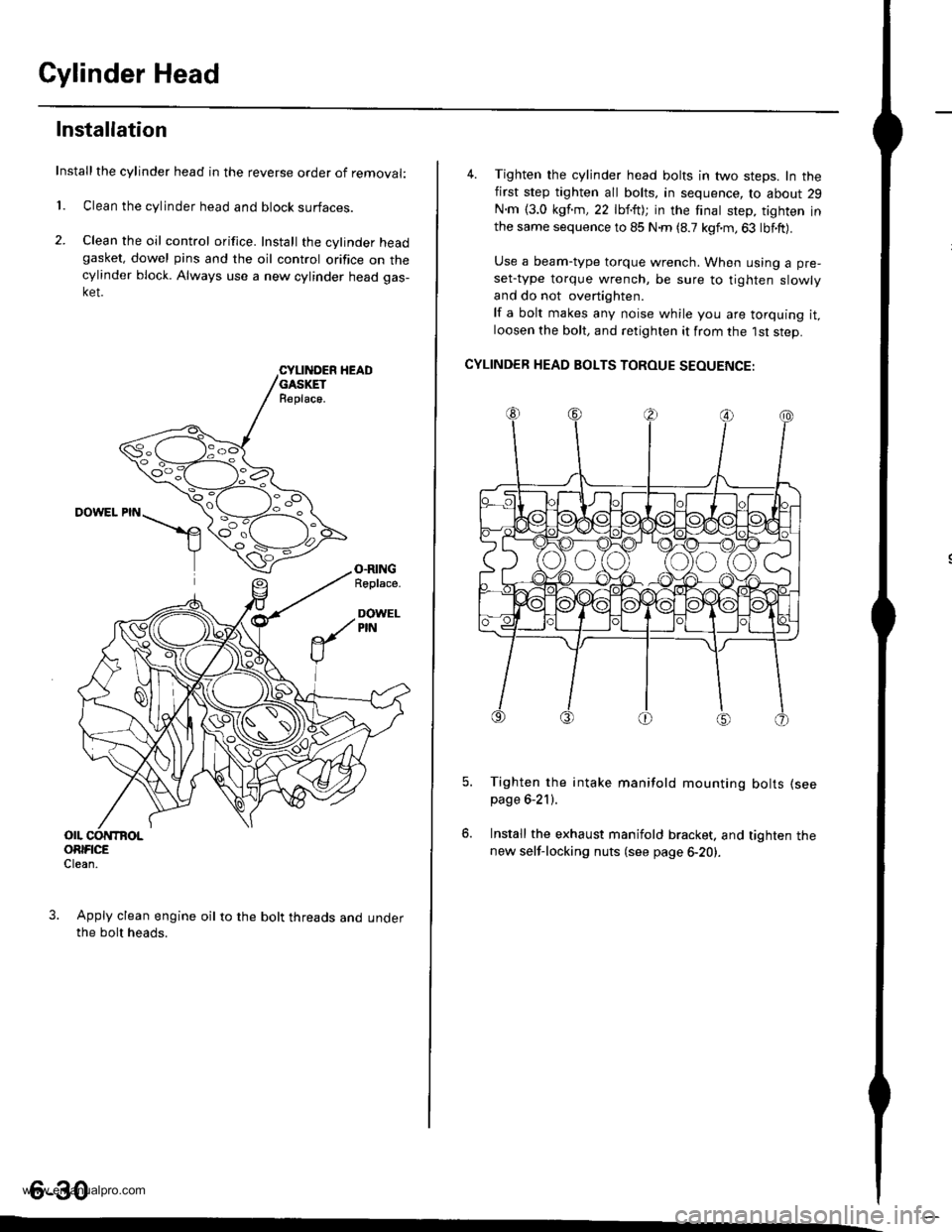
2. Clean the oil control orifice. Install the cylinder headgasket, dowel pins and the oil control orifice on thecylinder block. Always use a new cylinder head gas-ket.
CYLII{DER HEADGASKETR€place.
DOWEL PIN
O.RINGRoplace.
DOWELPIN
OIL CONTBOLORIFICEClean.
Apply clean engine oil to the bolt threads and underthe bolt heads.
4. Tighten the cylinder head bolts in two steps. In thefirst step tighten all bolts, in sequence, to about 29
N.m {3.0 kgf.m,22 lbf.ft); in the finat step, tighten inthe same sequence to 85 N.m (8.7 kgf.m,63 lbf.ft).
Use a beam-type torque wrench. When using a pre-
set-type torque wrench, be sure to tighten slowly
and do not overtighten.
lf a bolt makes any noise while you are torquing it,loosen the bolt, and retighten it from the 1st step.
CYLINDER HEAD BOLTS TOROUE SEOUENCE:
Tighten the intake manifold mounting bolts (see
page 6-21).
Install the exhaust manifold bracket. and tighten thenew self-locking nuts (see page 6-20).
6-30
www.emanualpro.com
Page 272 of 1395
Troubleshooting
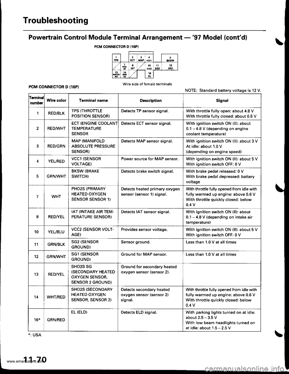
Powertrain Gontrol Module Terminal Arrangement -'97 Model (cont'd)
PCM CONNECTOR O {16PI
PCM CONNECTOR D (I6P)Wire side of f6male terminals
NOTE: Standard battery voltage is 12 V.
f.rminal
numbcrWir! colorT€rminal nam6DescriptionSignal
1RED/BLKTPS ffHROTTLE
POSITION SENSOR}
Detects TP sensor signal.With throttle fullv oDen: about 4.8 V
With throttle fullv closed: about 0.5 V
RE D,4/VHT
ECT (ENGINE COOLANT
TEMPERATURE
SENSOR
Detects ECT sensor signal.With ignition switch ON {ll): about
0.1 - 4.8 V (depending on engine
coolant temperature)
RED/GRN
MAP (MANIFOLD
ABSOLUTE PRESSURE
SENSOR)
Detects MAP sensor signal.With ignition switch ON (ll): about 3 V
At idle; about 1.0 V(depending on engine speed)
YEUREDVCCl (SENSOR
VOLTAGE)
Pow€r source for MAP sensor.With ignition switch ON (ll): about 5 V
With ignition switch OFF: 0 V
EG R N/WHT
BKSW (BRAKE
SWITCH)
Detects brake switch signal.With brake pedal released:0 V
With brake pedal depressed: battery
voltage
7WHT
PHO2S (PRIMARY
HEATED OXYGEN
SENSOR SENSOR 1)
Detects heated primary oxygen
sensor (sensor 1) signal.
With throttle fully opened from idle with
fully warmed up engine: above 0.6 V
With throttle quickly closed: below
0.4 v
8RED//E L
IAT (INTAKE AIR TEM.
PERATURE SENSOR)
Detects IAT sensor signal.With ignition switch ON lll): about
0.1 - 4.8 V (depending on intake air
temperaturel
10YEUBLUVCC2 (SENSOR VOLT-
AGEI
Provides sensor voltage.With ignition switch ON (ll): about 5 V
With ignition switch OFF: 0 V
11GRN/BLKSG2 (SENSOR
GROUND)
Sensor ground.Less than 1.0 V at all times
12GRN/WHTSGl (SENSOR
GROUND)
Ground for MAP sensor.Less than 1.0 V at all times
13RED/YE L
SHO2S SG(SECONDARY HEATED
OXYGEN SENSOR,
SENSOR 2 GROUND)
Ground for secondary heated
orygen sensor (sensor 2).
14WHT/RED
SHO2S (SECONDARY
HEATED OXYGEN
SENSOR, SENSOR 2)
Detects secondary heated
orygen sensor (sensor 2)
signal,
With throttle fully opened from idle with
fully warmed up engine; above 0.6 V
With throttle quickly closed: below
0.4 v
16*GRN/RED
EL (ELD)Detects ELD signal.With parking lights turned on at idle
about 2.5 - 3.5 V
With low beam headlights turned on
at idle: about 1.5 - 2.5V
1-70
www.emanualpro.com
Page 273 of 1395

Engine/Powertrain Control Module Terminal Arrangement - 38 - 00 Models
ECM/PCM CONNECTOR A (32P}
,/./5aIsca
,/ l,/t5ItsTs
n2ls!uCI
Wire side ot female terminalsECM/FCM CONNECTOR A {32P)NOTE: Standard baftery voltage is '12 V.
D93criptionSignal
3BLU2WBS {EVAP BYPASSSOLENOID VALVE)Drives EVAP bvoass solonoid valve.With ignirion switch ON {ll)r battery voltage
LT GRNMHTVSV {EVAP CONTROL CANISTEB VENT SHUT VALVE)D.ives EVAP controlcanisler vent shutWith ig^ition switch ON (ll): battery voltage
5',BLUCRS (CRUISE CONTROL SIG'NAL)Shift Oown signalinputfrcm cruise conWhen cruise control is used: pulses
6RED/YEL
PCS (EVAP PURGE CONTROLSOLENOID VALVE)Drives EVAP purge controlsolonoid valve.With engins running, engine coolant, below 154'F(68'C)r battery voltageWith engine running, engine coolant, above 154"F{6a'C}r duty conl.olled
8ELIOWHTSO2SHTC (SECONDARVHEATED OXYGEN SENSORHEATER CONTROL)
Drives sacondary heated oxygen sensorWith ignition switch ON (ll): banery voltageWith fully warmed up engine running: duty
10BRNSCS (SERVICE CHECX SIGNAL)Detects seNics check conneclor signal(he signalcausing a DTC indicatjon)with rhe lerminal connected:0 vWith the rerminaldisconnectedrabout 5 v or
l4'rGRN/8LKD4IND (D4INDICATOR)+3DIND (D INDICATORTIDrives D4*3. Dr'indicaior light.W,rh 04' , O" indrcator light turned O batter,
With D4*3, D*. indicator light turned OFFr0 V
16GRNI/ELFLR (FUEL PUMP RELAY)Drivss fusl pump relay.0 V for iwo seconds after ru'nin9 ign'lion swilchON lll), then banery voltage
17AL|(/REDACC (I/C CLUTCH RELAY}Drives l,/C clurch rclay.With compressor ONr0 VWith compressor OFF: battery voltage
18GRN/ORNMIL (MALFUNCTION INDICA.TOR LIGHT)Driv€s MlL.With MlLturned ON:0 VWith MIL turned OFF: battery voltage
19BLUNEP (ENGINE SPEED PULSE)Outputs engine spsed pulse.With sngine runnin9: pulses
20GRNFANC {RADIATOR FAN CONTROL)Drives r6diator fan rslay.With radaator fan running:0 VWith radaatorfan stopped: battery vollage
218LU/t/ELK-LINESends and receiv€s scan toolsignal.With ignition switch ON (ll): p'rlses
23WHT/REDSHO2S (SECONDARY HEATEDOXYGEN SENSOR. SENSOR 2iDetects secondary h€at€d oxygen sensorWith throttle fully opened from idle wilh fullywalmed up engine: above 0.6 Vwith rhrottle quickly closed: below 0-4 V
21BLU/WHTSTS (STARTER SWITCH SIG,NAL}Dotocts srarter switch signal.Whh staner switch ON (lll): batlery voltageWith srarter switch OFF: 0 V
26GBNPSPSW {P/S PsESSUFESWITCH SIGNAL)Detecrs PSP switch signal.At idle with steeing wh€el in stBighl ahead position: 0 VAt idls with nee ng wheel al full lockr banory voltage
2fBLU/BEOACS (Ir'C SWTCH SIGNAL}D€tects ly'C switch signal.With Ay'C switch ON:0 VWith l/C swil€h OFF: about 5 V
2A'\WHT/NEDSLU {INTERLOCK CONTROLUNIT)Orives interlock control unil.With ignilion switch ON (ll)and brake pedaldepressed: battery vohage
29LT GRNPTANK (FUEL TANK PRES'SURE SENSOR)Detocts fueltank pressure sensor signal.With agnition switch ON (ll) and fuel fill capopensd; about 2.5 v
GBN/FEDEL (ELD}Detects ELD signal.Wirh paaing rightstumed on at idle:about 2.5 - 3.5 VWith low beam headlights tumed on at idle:about 1.5-2.5V
GRN/WHTBKSW (BRAKE SWTTCH)Dst€cts brake switch signal.Wirh brake pedal released:0 VWith brake pedal depressed: battery vollage
13: '98 modsl
15: USA(cont'd)
11-71
www.emanualpro.com
Page 393 of 1395
Fuel Tank
Replacement
1. Relieve the fuel pressure (see page 11-178).
2. Fold the left rear seat cushion forward, and remove the base frame cover {see section 20).
3. Remove the access panel from the floor.
4. Disconnect the 5P connector 1C562) and 6P connector (C580) ('98-00 models)'
5. Disconnect the fuel return hose and quick-connect fittings {see page 11-175}
6. Jack up the vehicle, and support it with jackstands.
7. Remove the middle floor beam.
8. Remove the drain bolt, and drain the fuel into an approved contaaner.
g. Disconnect the hoses (see page 11-173, 174). slide back the clamps. then twist hoses as you pull, to avoid damaging
them.
10. Place a jack, or other suppon, under the tank
11. Remove the strap nuts, and let the straps fall free
12. Remove the fuel tank. lf it sticks on the u ndercoat applied to its mount, carefu lly pry it off the mount,
'13. lnstallthe drain bolt with a new washer, then coat the drain bolt with Noxrust 1248'
Allow the Noxrust to dry for 20 minutes.
14. Install parts in the reverse order of removal.
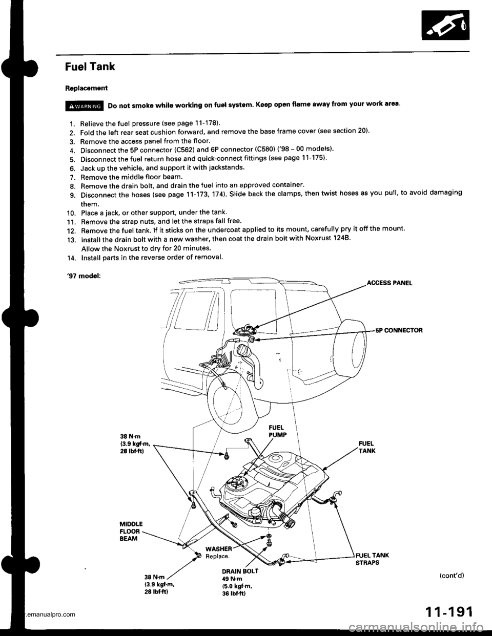
'97 modol:AOCESS PANEL
CONNECTOR
@ Do not smoke while working on fuol systam Keep open flame away from your work area'
DRAIN EOLT49 N.m15.0 kgf'm,36 rbt frl
(cont'd)
1 1-191
www.emanualpro.com
Page 876 of 1395
Power Steering Gearbox
Removal
Note these items during removal:
. Using solvent and a brush, wash any oil and dirt off
the valve body unit its lines, and the end if the gear-
box. Blow dry with compressed air.
. Be sure to remove the steering wheel before discon-
necting the steering joint. Damage to the cable reel
can occur.
. With 4WD. tilt the engine with a jack to expand the
clearance between the transfer assembly and rear
beam when removing the steering gearbox from the
rear oeam.
Do not remove the steering gearbox by removing the
transfer assembly from the transmission.
1. Drain the power steering fluid as described on page'17-15.
Raise the vehicle, and suppon it on safety stands in
the proper locations (see section 1).
Remove the front wheels,
Remove the drive/s airbag assembly {see section 24).
Remove the steering wheel {see page 17-18).
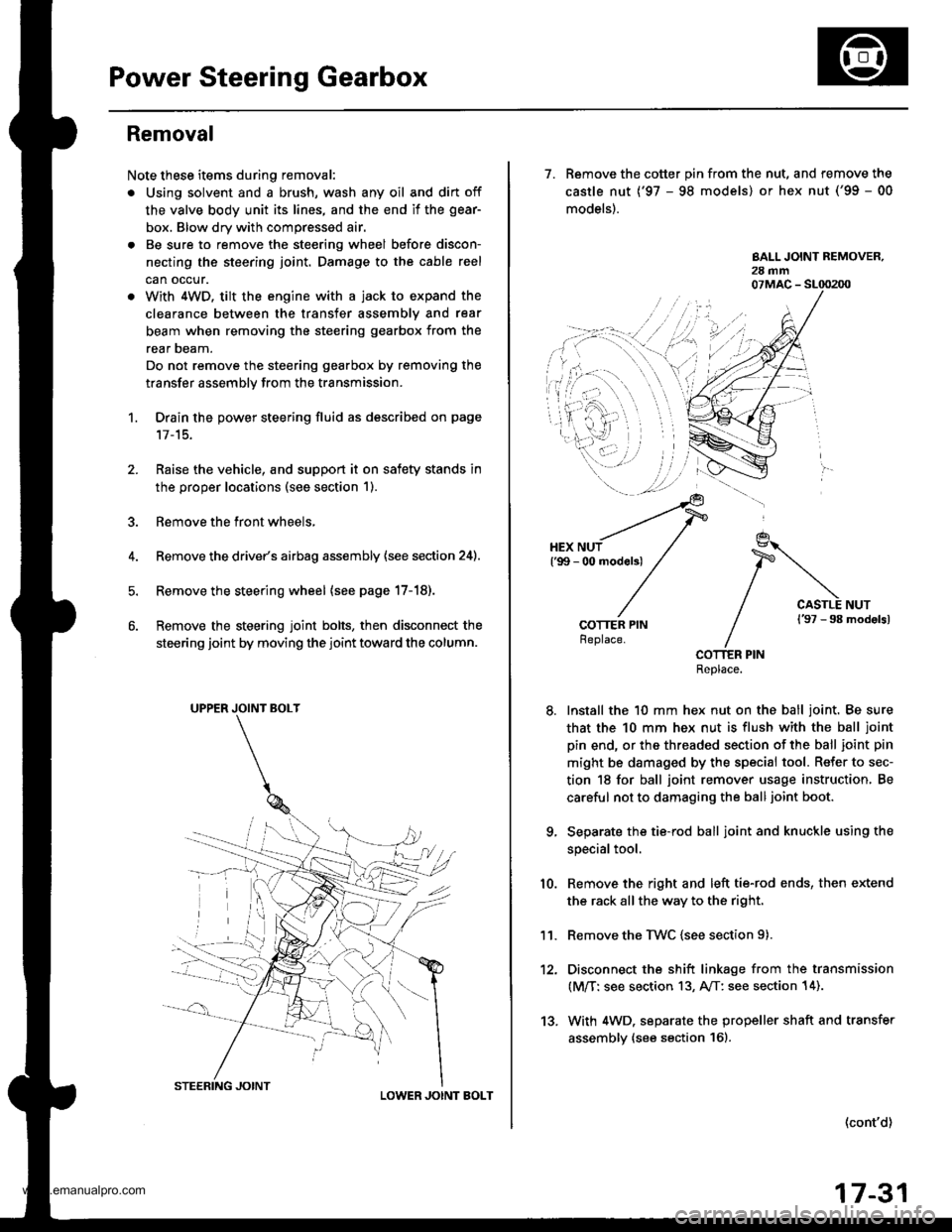
Remove the steering joint bolts, then disconnect the
steering joint by moving the joint toward the column.
UPPER JOINT BOLT
LOWER JOINT BOLT
13.
7. Remove the cotter pin from the nut, and remove the
castle nut {'97 - 98 models) or hex nut ('99 - 00
models).
COTTER PINReplace.
Install the 10 mm hex nut on the ball joint. Be sure
that the 10 mm hex nut is flush with the ball joint
pin end, or the threaded section of the ball joint pin
might be damaged by the special tool. Refer to sec-
tion 18 for ball joint remover usage instruction, Be
careful not to damaging the ball joint boot.
Separate the tie-rod ball joint and knuckle using the
special tool.
Remove the right and left tie-rod ends, then extend
the rack all the way to the right.
Remove the TWC (see section 9).
Disconnect the shift linkage from the transmission
(M/T: see section 13, A/T: see section 14).
With 4WD. separate the propeller shaft and transfer
assembly (see section 161.
10.
11.
(cont'd)
17-31
www.emanualpro.com
Page 879 of 1395
Power Steering Gearbox
Removal (cont'dl
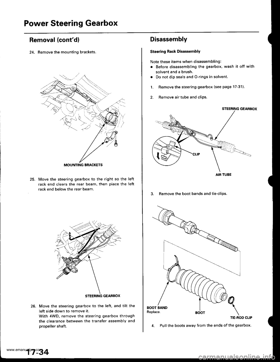
24. Remove the mounting brackets.
25.lvlove the steering gearbox to the right so the
rack end clears the rear beam, then place the
rack end below the rear beam.
left
left
Move the steering gearbox to the left, and tilt the
left side down to remove it.
With 4WD. remove the steering gearbox through
the clearance between the transfer assembly and
propeller shaft.
MOUNTING BRACKETS
STEEBING GEARBOX
17 -34
4. Pull the boots away from the ends of the gearbox.
Disassembly
Steering Rack Disassembly
Note these items when disassembling:
. Before disassembling the gearbox, wash it off with
solvent and a brush.
. Do not dip seals and O-rings in solvent.
1. Remove the steering gearbox (see page 17-31).
2. Remove airtube and clips.
3. Remove the boot bands and tie-clips.
AIR TUBE
www.emanualpro.com
Page 896 of 1395
lnstallation
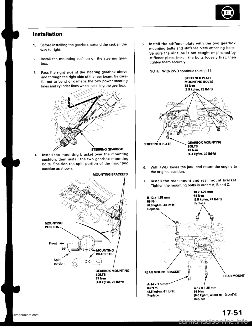
1. Before installing the gearbox, extend the rack all the
waY to right.
2. lnstall the mounting cushion on the steerlng gear-
box.
3. Pass the right side of the steering gearbox above
and through the right side of the rear beam. Be care-
ful not to bend or damage the two power steering
STEERING GEARBOX
Install the mounting bracket over the mounting
cushion. then install the two gearbox mounting
bolts. Position the split portion of the mounting
cushion as shown.
MOUNTING BBACKETS
GEARBOX MOUNTINGBOLTS39 N.m14.0 kgf.m, 29 lbf.ft)
:-
/
5. Install the stiffener plate with the two gearbox
mounting bolts and stiffener plate attaching bolts.
Be sure the air tube is not caught or pinched by
stiffener plate. Install the bolts loosely first. then
tighten them securely.
NOTE: With 2WD continue to step 11.
STIFFENER PLATEMOUNTING BOLTS38 N.m
1.
With 4WD, lower the iack, and return the engine to
the original Position.
lnstall the rear mount and rear mount bracket.
Tighten the mounting bolts in order: A, B and C.
8.12 x 1,25 mm
59 N.m(6.0 kgt.m. *l lb{'ftlReplace.
10 x 1.25 mm6,a N.m
16.5 kst.m, 47 lbl'ft)R€place.
)\^
o(]
17-51
www.emanualpro.com
Page 1088 of 1395
Frame Repair Chart
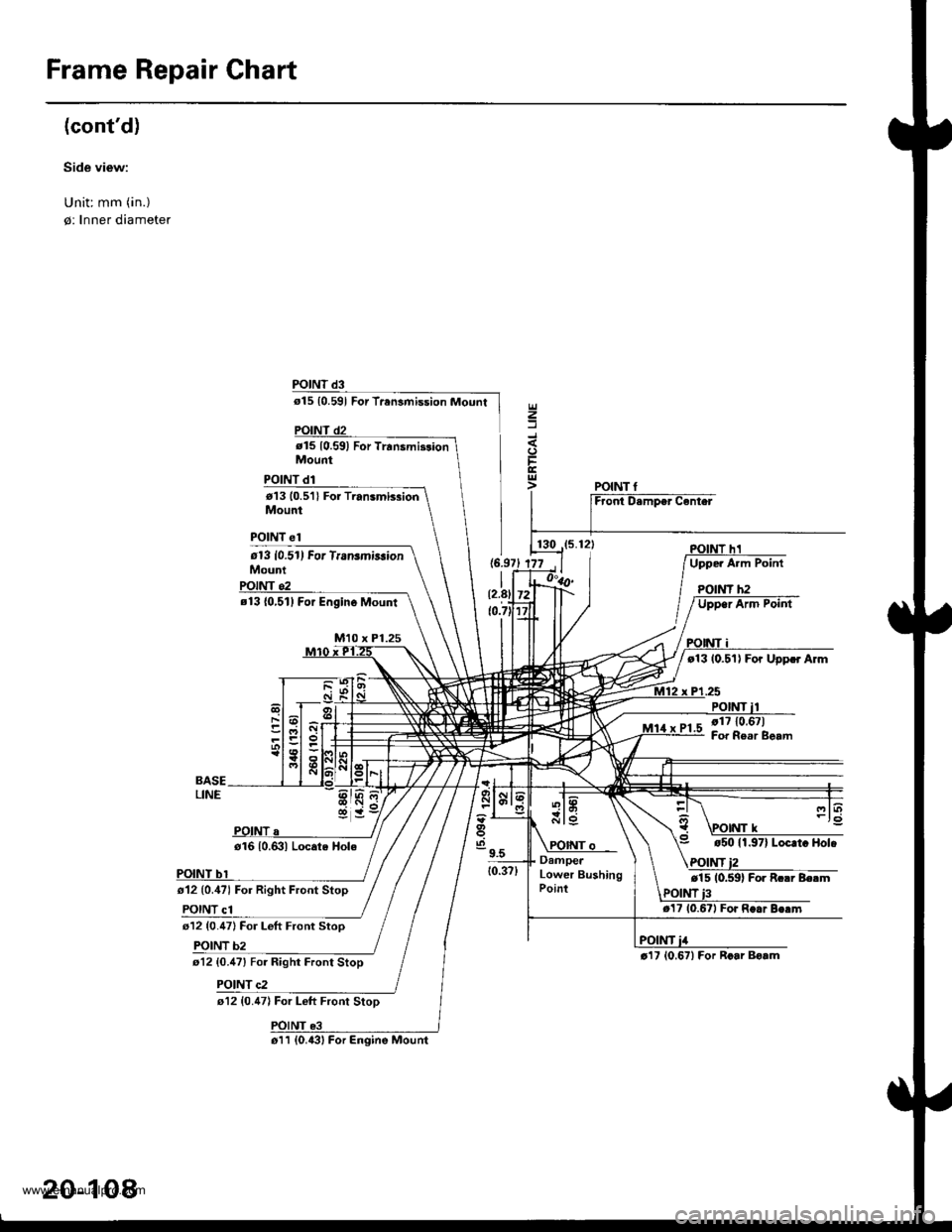
(cont'd)
Side view:
Unit: mm (in.)
0: Inner diamete.
POINT d3
o15 {0.591 For Trensmission Mount
d15 10.591 For Trrnsmi3donMount
POINT d1
t13 10.5'll For Transmb3ionMount
POINT el
613 10.51) For TransmirsionMouni
z
t13 {0,511 For Engin6 Mount
M10 x Pl.25
t13 10.51) For Uppcr Arm
.25
POINT,1710.67)Fof Re.r Beam
o12 (0.,171 For Right Front Stop
POINT c1
o16 10.631 Locate Hole
612 {0.47} For Left Front Stoo
b2
r12 {0.47) For Left Front StoD
t5011.97| Locrt. Hol.
POINT
t17 10.671 Fo. R..r
r'17 10.671 For Rcar Bo.mt12 {0.47} For Right Front Stop
POINT c2
130POINT h1
DamperLower BushingPoint
o11 (0.{31 For Engine Mount
20-108
www.emanualpro.com
Page 1089 of 1395
POlNTx.y / I
'sad
POINT m3, m4
Upper Arm
M12 x P1.25
Locate Hole
POINT 3, s1
o14 {0.551 For Trailing Aim
POINT v
Fuel Tank Strap Poinr
2700.5 (106.32)SECTION BBRear Damoer Center
POINT n
FOINT
rg (0.3) Fuel TStrap Center
271,1(10,6.9)
o2010.8| Locate Hole
For Rear Cros3 Beam
For Reer Cross Beam
POINT w
Bear Damper LowerBushing Point
I
\-
ql
ol
.df
20-109
www.emanualpro.com
Page 1204 of 1395

Power Distribution
Fuse
1
3
5
6
7
I
9
10
11
12
13
14
"^
RED/B LU
RED/GRN
WHT/BLK
RED/VVHT
YEUBLK
RED
GRN/BLK
BLU/BLK
YEVBLK
YEUGRN
RED
BLK/YE L
BLK/VVHT
17
7.5 A
7.5 A
BLVBLU
BLKA/EL
18
19
20
22
7.54
7.54
l0 A
10 A
YEUBLK
YEVRED
BLKAr'YHT
RED /VHT
RED/YE L
Fuse-to-Component(sl Index (numerical sequencel (cont'dl
Under-dash Fuse/Relay Box:
Capacity
10 A
10 A
10 A
10 A
20A
204
15A
204
204
7.5 A'15 A
7.5 A
7.5 A
Wire ColorCircuit{s) Protected
Not used
Not used
Rear window washer motor (via switch)
Rear window wiper control unit ('97 model)
Rear window wiper motor
Daytime running rights resister {Canada)
Right headlight {High beam}
Daytime running rights resister (Canada)
High beam indjcator light
Left headlight (High beam)
Rear accessory socket (via relay)
Left rear power window motor (via switch)
Right rear power window motor (via switch)
Distributor (ignition control module)
Front passenger's power window motor (via switch)
Driver's power window motor {via switch)
Power window master switch (power window control unit)
Turn signal/hazard relay (via switch)
PGM-FI main relay
SRS unit (VA)
Cruise control unit (via switch)
Cruise main switch indicator light
Alternator
Charging system light
ELD unit (USA)
EVAP bypass solenoid valve ('98 - 00 models)
EVAP control canister vent shut valve ('98 - 00 models)
EVAP purge control solenoid valve
Primary HO2S
Secondary H02S
VSS
ABS control unit
Option connector (lG2)
Ay'C compressor clutch relay
Blower motor high relay
Blower motor relay
Condenser fan relay
Heater control panel
Left power mirror actuators (via switch)
Mode control motor
Radiator fan relay
Recirculation control motor
Right power mirror actuators (via switch)
Daytime running lights control unit (Canada)
Back-up lights
Reverse relay (A"/T)
Daytime running lights control unit (Canada)
Right headlight (Low beam)
Left headlight (Low beam)
23-44
www.emanualpro.com