speedometer HONDA CR-V 1999 RD1-RD3 / 1.G Workshop Manual
[x] Cancel search | Manufacturer: HONDA, Model Year: 1999, Model line: CR-V, Model: HONDA CR-V 1999 RD1-RD3 / 1.GPages: 1395, PDF Size: 35.62 MB
Page 267 of 1395

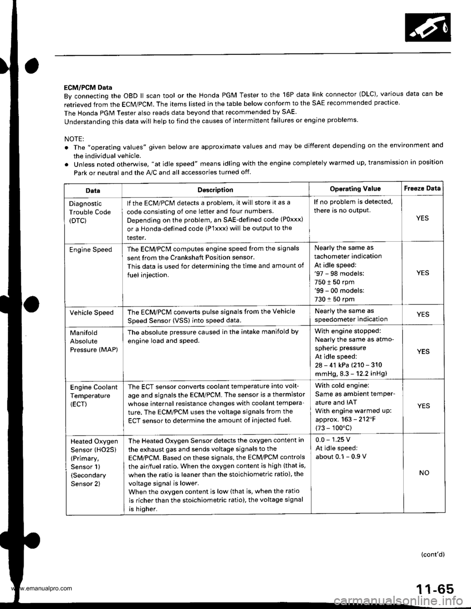
ECM/PCM Data
By connecting the OBD ll scan tool or the Honda PGM Tester to the 16P data link connector (OLC), various data can be
retrieved from the ECM/PCM. The items listed in the table below conform to the SAE recommended practice
The Honda PGM Tester also reads data beyond that recommended by SAE.
understanding this data will help to find the causes of intermittent failures or engine problems.
NOTE:
The ',operating values" given below are approximate values and may be different depending on the environment and
the individual vehicle.
Unless noted otherwise. "at idle speed" means idling with the engine completely warmed up, transmission in position
Park or neutral and the A,./C and all accessories turned otf.
DataDesc.iptionOp€rating ValuoFreeze Data
Diagnostic
Trouble Code
(DTC)
lf the ECM/PCM detects a problem, it will store it as a
code consisting of one letter and tour numbers
Depending on the problem, an SAE-defined code (Poxxx)
or a Honda-defined code (P'lxxx) will be output to the
tester.
lf no problem is detected,
there is no output.
YES
Engine SpeedThe ECN4/PCN4 computes engine speed from the signals
sent from the Crankshaft Position sensor.
This data is used for determining the time and amount of
fuel iniection.
Nearly the same as
tachometer indication
At idle speed:'97 - 98 models:
750 t 50 rpm'99 - 00 models:
730 f 50 rpm
YES
Vehicle SpeedThe ECM/PCM converts pulse signals from the Vehicle
Speed Sensor (VSSI into speed data.
Nearly the same as
speedometer indicationYES
Manifold
Absolute
Pressure (MAP)
The absolute pressure caused in the intake manifold by
engine load and speed.
With engin6 stopped:
Nearly the same as atmo-
spheric pressure
At idle speed:
2a - 41 kPa {210 - 310
mmHg, 8.3 - 12.2 inHg)
YES
Engine Coolant
Temperature
{ECT)
The ECT sensor converts coolant temperature into volt-
age and signals the ECM/PCM. The sensor is a thermistor
whose internal resistance changes with coolant tempera-
ture. The ECM/PCM uses the voltage signals from the
ECT sensor to determine the amount of injected fuel
With cold engine:
Same as ambient temPer-
ature and IAT
With engine warmed uP:
approx. 163 - 2'12'F
(73 - 100"c)
YES
Heated Oxygen
Sensor (HO25)
(Primary,
Sensor 1)
(Secondary
Sensor 2)
The Heated Oxygen Sensor detects the oxygen content in
the exhaust gas and sends voltage signals to the
ECMiPCM. Based on these signals, the ECM/PCM controls
the airlfuel ratio. When the oxygen content is high (that is.
when the ratio is leaner than the stoichiometric ratio), the
voltage signal is lower.
When the orygen content is low (that is, when the ratio
is richer than the stoichiometric ratio), the voltage signal
is higher.
0.0 - 1.25 V
At idle speed:
about 0.1 - 0.9
NO
(cont'd)
1 1-65
www.emanualpro.com
Page 738 of 1395

Differential
lllustrated Index
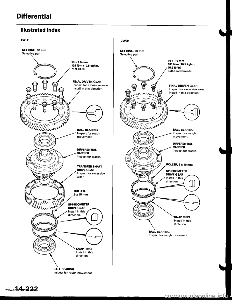
'lWD:
SET RING, 80 mmSelective part
10 x 1.0 mm103 N.m (10.5 kgt.m,?5.9 tbtftl
FINAL ORIVEN GEARlnspect for excessive wear,Install in this direction.
BALL BEARINGInspect for rough
DIFFERENTIAI.CARRIERlnspect for cracks.
TRANSFER SHAETDNlvE GEARInspect for excessive
SPEEDOMETERDRIVE GEARInstall in thisdirection.
SNAP RINGInstall in thisdirection.
BALL BEARINGInspect for rough movement,
14-222
2WDl
SET nlNG, 80 mmSel6ctive part
A,U
,gBc
10 x 1.0 mm103 N.m {10.5 kg[.m,75.9 tbt.ftlLeft-hand threads
FINAL ORIVEN GEARInspect for excessive wear,Install in thls direction.
BALL BEABINGInspect for rough
DIFFERENTIAI.CARRIERInspect for cracks.
ROLLER,5 x 10 mm
SPEEDOMETERDRIVE GEARInstall in thisdirection.
SNAP RINGInstall in thisdirection.
BALL BEARING
www.emanualpro.com
Page 740 of 1395

Differential
Differential Carrier Replacement
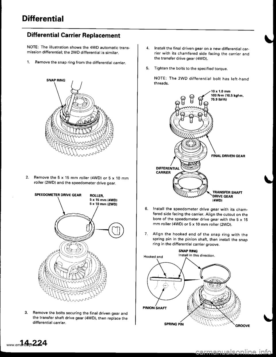
NOTE: The illustration shows the 4WD automatic trans-mission differential; the 2WD differential is similar.
1. Remove the snap ring from the differential carrier.
Remove the 5 x 15 mm roller (4WD) or 5 x 10 mmroller (2WDl and the speedometer drive gear.
SPEEDOMETER DRIVE GEAR RoI I FP
Remove the bolts securing the final driven gear andthe transfer shaft drive gear (4WD), then replace thedifferential carrier.
5 x 15 mm (/tWD)5 x 10 mm {2WDl
14-224
SPRING PINGROOVE
Install the final driven gear on a new differential car-rier with its chamfered side facing the carrier andthe transfer drive gear (4WD),
Tighten the bolts to the specified torque.
NOTE: The 2WD differentiat bolt has left-handthreads,
10 x 1.0 mm103 N.m 110.5 kd.m,7s.9 rbr.ft)
7.
FINAL DRIVEN GEAR
TRANSFER SHAFT
Install the speedometer drive gear with its cham-fered side facing the carrier. Align the cutout on thebore of the speedometer drive gear with the 5 x 15mm roller (4WD) or 5 x 10 mm roller (2WD).
Align the hooked end of the snap ring with thespring pin in the pinion shaft. then install the snaoring in the differential carrier groove
SNAP RINGInstall in this direction.Hooked end
PINION SHAFT
{4WDl
www.emanualpro.com
Page 1161 of 1395

Body Electrical
Speciaf Toofs ,...,..,.............-.23-2
Troubleshooting
Tips and Precautions ......,.,..........,.................. 23-3
Five-step Troubleshooting ........,.,.,...,,.,......... 23-5
Wire Color Codes ...,....,.. 23-5
Relay and Control Unit Locations
Engine Compartment ..,.,......,......................... 23-6
Dashboard ,.,.,..............-.- 23-7
Door ....................... .........23-10
Index to Cilcuits and Sysiems
Accessory Socket .. ,....,.,..,.,. 23-95*Airbags ................ .,....,. Sestion 24
Air Conditioning ,.,.,.... Section 22
Alternator ................... Section 4
Anti-lock Brake System {ABSI ................... Section 19'A/T Gear Position Indicator ....................... Section 1,1
Automatic Transmission System ...........,.. Section 14
Battery ................... ..............23-50
Blower Controls .,...,.,, Section 22
Charging System ....... Seqtion il
Clock -'98 Model ................ 23-98
Connector ldentification and Wire HarnessRouting .................. ......... 23.11
Cruise Control ............ Ssction 4
Dash Lights Brightness Contlo||er ..................... 23-90
Fan Conlrols ...,......,.... Section 10
Fuel Pump ,..,.,...,....,.... Section 11
Fuses...................... .,,.,.,.,.,,.,23-40*Gauges
Circuit Diagram ......-....-..23-58
Fuel Gauge .....,.,..... Section 11
Speedometer ..,..........,... 23-56
Ground Distribution ,....,.,...23-46
Hatch Glsss ODenor .........................,.,.,.,.,..,.,.,.,,. 23-121
Heater Controls .-........ Soction 21*Horns.,...,..,.,.,....... ................23"104*fgnition Switch ,,.,.,..,.,.,,.,.,.,23-51
lgnition Key Light System -'97 Mod6l .............. 23.88
-+
BODY
www.emanualpro.com
Page 1216 of 1395

Gauge Assembly
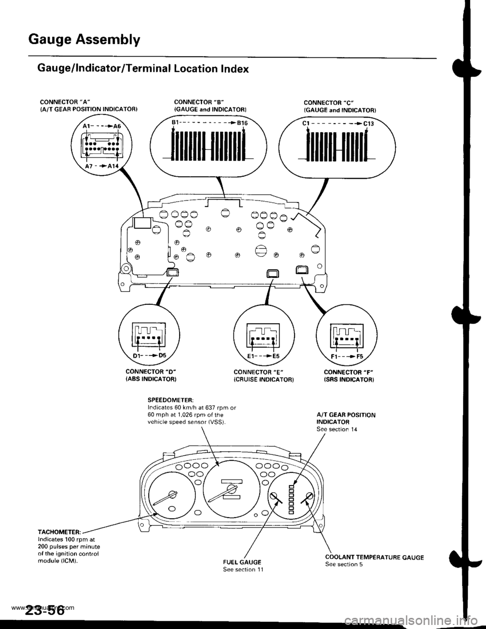
Gau ge/lndicator/Terminal Location Index
CONNECTOR "A"
{A/T GEAB POSITION INDICATOR)
CONNECTOR "D-
{ABS INDICATOR)CONNECTOR "E"
{CBUISE INDICATOR'CONNECTOR "F"
{SRS INDICATOR}
SPEEDOMETER:Indicates 60 km/h at 637 rpm or60 mph at 1,026 rpm ofthevehicle speed sensor (VSS).
TACHOMETER:lndicates 100 rpm at200 pulses per minuteof the ignition controlmodule (lCM).
23-56
a1___-__-____>816
JilililIJililil1
cl --------->cl3
JililtHililL
,
.. "€""^
o o ue ou
t)1- --->t)5E1- - -->E5Fl---->F5
oo/ \oo
www.emanualpro.com