transmission troubleshooting HONDA CR-V 1999 RD1-RD3 / 1.G Workshop Manual
[x] Cancel search | Manufacturer: HONDA, Model Year: 1999, Model line: CR-V, Model: HONDA CR-V 1999 RD1-RD3 / 1.GPages: 1395, PDF Size: 35.62 MB
Page 390 of 1395
![HONDA CR-V 1999 RD1-RD3 / 1.G Workshop Manual
Fuel Supply System
PGM-FI Main Relay (contdl
Troubleshooting
lc(}21PGM.FI MAIN RELAY 7P CONNECTOR
GND
trTr]--Flq
FI,TilI A
Y
Wire side ot female terminals
- Engine will not start.- InsDection ol PG HONDA CR-V 1999 RD1-RD3 / 1.G Workshop Manual
Fuel Supply System
PGM-FI Main Relay (contdl
Troubleshooting
lc(}21PGM.FI MAIN RELAY 7P CONNECTOR
GND
trTr]--Flq
FI,TilI A
Y
Wire side ot female terminals
- Engine will not start.- InsDection ol PG](/img/13/5778/w960_5778-389.png)
Fuel Supply System
PGM-FI Main Relay (cont'dl
Troubleshooting
lc(}21PGM.FI MAIN RELAY 7P CONNECTOR
GND
trTr]--Flq
FI,Til'I A
Y
Wire side ot female terminals
- Engine will not start.- InsDection ol PGM-FI mainrelay and relay harness,
Check fo. an open in the wireIGND linol:1. Turn the ignition switch OFF.2. Disconnect the PGM Fl mainrelay 7P connector.3. Check for continuity betweenthe PGM'FI main relay 7P con-nector terminal No. 3 and bodyground.
Repair opcn in th€ wire betweenthe PGM-FI main relav and G101.
Check tor an open or short in thewiro (BAT line):Measure voltage between thePGM'FI main relay 7P connectorterminal No. 7 and body ground.- Repai. open or short in lhewir6 belween the PGM-FImain relay and the Fl E/M (15Al fu3e.- Replace th6 FIE/M (15 Altus6in th€ under-hood fuse/.6lay
ls there baftery voltage?
Check lor an open or short in thewire (lGl line):L Turn the ignition switch ON (ll).2. Measure the voltage betweenthe PGM-FI main relay 7P connectorterminal No. 5 and bodyground.- Repair open or shorl in thewire between the FGM-FI mainrelay and the No. 13 FUELPUMP 115 A) tuse.- Replaco the No. 13 RJEL PUMP115 A) luse in the und6.-d$hfuso/ relav box.Check for an open or short in thewire {STS line):1. Turn the ignition switch to theSTART (lll) position.NOTE:. M/T: Clutch pedal must bedepressed.. A/T: Transmission in E orElposition.2. Measure the voltage betweenthe PGM-Fl main retay 7Pconnector terminal No. 2 andbody ground.- Repair open or short in thewire betwe€n the PIGM-FI m.inrclay and th€ No. 31 STARTERSlGllAL 17.5 A) tuse.- Repl.ce the No. 31 STARTERSIGNAL 17.5 Al tuse in theunder-dash tuse/relay box.('97 model: To page 11-189)('98 00models:To page 1l 190)
1 1-188
www.emanualpro.com
Page 407 of 1395

'97 model:
The scan tool indicates Diagnostic Trouble Code (DTC) P0441: Evaporative Emission (EVAP) control system
insufficient purge flow.
Description
By monitoring the purge line vacuum with the MAP sensor, the PCM can detect insufficient EVAP control system purge
flow.
Possiblo Cause
. EVAP Purge Control Solenoid Valve
. EVAP Purge Control Solenoid Valve Circuit
. EVAP Control Canister
. Vacuum Lines
. PCM
Troubleshooting Flowchart
EVAP PURGE CONTROL
SO1TNOID VALVE 2P
CoNNECTOR (C108)
(v)
YL
Wire side of female
termrnals
(cont'd)
11-205
Th€ MIL has b€en reooited on.DTC P0441 is .tored.
Problem verificationl1. Start the engine. Hold theengine at 3,000 rpm with noload (in Park or neut.al) untilthe radiator fan comes on.2. Do the PCM Reset Procedure.3. Connect the SCS service con-nector,4. Test drive under following con'ditions on the road.- without any electrical load- Transmission in @ or @position- Engine speed between1 ,2OO - 2,4OO rpfi.- Decelerate from 50 mph (80
km/h)to 15 mph (24 km/h)Intermittent trilure, sydern is OKat this time. Check for Door con-nections or loose wir€3 at C108
IEVAP purge control solonoidvalvol .nd at the PCM.
ls DTC P0441 indicated?
Check tor an open in the wire (lcl
linel:1. Turn the ignition switch OFF.2. Disconnect the EVAP purge
control solenoid valve 2P con-nector.3. Turn the ignition switch ON (ll).
4. Measure voltage between bodyground and the EVAP purge
control solenoid valve 2P con-nector terminal No. '1,
R€pafu open in thc wir6 b€tw€enthG EVAP purge control solenoidvalve and the No. 15 ALTEBNA-TOR SP SENSOR (7.5 A)fuse.
ls there batlery voltage?
(To page 11'206)
www.emanualpro.com
Page 517 of 1395

Automatic Transmission
Special Tools . 14'2OescriptionGeneral Operation . .... 14 3Power Flow . . .. '14_6
Electronic Control System .. .. . . .. .14_15Hydraulic Control .. 14 24Hydraulic Flow....-....... .. . .... .. .. . 14_29Lock'up Syslem .. .'t4'39Electrical SystemComponenl Locdlrons 14 45
PCM Circuil Dragram (A/T Control Svstem)'97 Model ....................... . . .. - . ... .14-46'98Model ................. . ... .. .. .1450'99 00Models.... . .... . . . 1452
PCM Terminal Voltage/Measuring ConditionsA"/T Control System-'97Model ...... ..14'48A,/T Control System -'98 00 Models . . .. . . 14 54
Troubleshooting Procedures .. ..... ... - 14_56Svmotom to comoonent CharlEiectr,cal Syslem -'97 Model . . 14 60Electrical System -'98 - OO Models . .. . . 14_62Electrical Troubleshooting ('97 Model)Troubleshooting Flowaharts .... ..... . .. . . 14_64
Electrical Troubleshooting ('98 - 00 Models)Troubleshootinq Flowclt"n" .... . ....- . .14-93ElectricalTroublesliooting('99 00Models)Troubleshootino FlowchartO/D OFF Indicator Light Does Not Come On 14 131
O/D OFF Indicator Liaht On ConstantlY . . . .1!-132O/D OFF Indicator Light Does Not Come OnEven Though O/D Switch ls Pressed . .... - 14_133
Lock up Control Solenoid Valve A,/B AssemblyTest....................-......... . .14-135Replacement . .ll_135Shifr ControlSolenoid Valve Ay'B Assembl,Test .............................. . .. 14-136
Replacement..............- . .14'136Linear Solenoid AssemblYTest.............................................. .. .... . 14_137Replacement .. . 14138Marnshaftlcountershafl Speed SensorsReplacement ...-... 14_138A/T Gear Position SwitchTest ..........................-... . .. 14-139ReplacementA/T Gear Positionlndicator.................. 14-140
Valve Eodynepair ............................... ..... . . .. - . .. ... 14 192
Assembly .................... .. 1{_193
Valve CapsDesciiption....-........................ .. ...... 14194
tnspeition ................... .. 14' 195
N4ain Valve BodyDisassembly/lnspection/Reassemblv - ...... .. 14_196
Secondarv Valve BodYDisassemblv4nspectron/ReassemblY .. . 14 198
Reoulator Valve Bodvbisassembtv,lnspiction/Reassemblv . 14199
Servo EodvDisassembly/lnspection/Reassembly ... ....14'200
Lock'uo Valve BodYDis;ssembly/lnspection/Reassembly .... . 14_201
MainshaftDisassembly/lnspection/Reassembly .. .. .. ..14'202
Inspection ....-.............. ..11_203
Sealing RingsReilaceient ...... ..... . 14'204
CountershaftDisassembly/lnspection/Reassembly .. . . . . . 11-205
Disassembly/Reassemb|y . . ........ ...... . .. 14_206Inspedron ................ . .... . 14 207
One wav ClutchDisassembly/lnspection/ReassemblY ... 11_209
Sub-shaftDisassembly/lnspection/Reassembly ... . .. . 14-210
oisassembly/Re6ssembly . . ... .-...... . . ..14-211
Sub-shaft BearingsReplacement .......14'212
Clutchllfustrated Index .......... . . .14-213
Disassembly .... .. .....14-216Reassembfy .... . .. .. . 14'218
Differentialllfustrated Index " 14-222Backlash Inspection . .... . .14'223
Bearing Repiacement .. 11-223
Differe-ntial Carrier Replacement .. .. . . . .. ..11-2?4
OifSeal Replacement. . .. 14'225
Side Clearance lnspection . . - .. ... . - ...... . .. 11'226
Transmission Housing BearingsMainshaJVCountershaft EearingsRepfacement .......14221Sub'siralt Eearing Replacement . . . . . . . . . ..11'224
Toroue Converter Housing BearingsMainshattEearing/OilSe6lReplacement . .. l4229
Countershaft Bea;ing Replacement.. .... .. ..14-230
Input Test - '97 - 98 ModelsInput Test '99 - 00 Models
Symptom to-Component ChartHydraulic System ...............
Checking
Removal ...,lllustrated Index (4WD)
Interlock SystemInterlock ControlUnit lnputTest. -..... -.. .... . - 14 144* Key Interlock Solenoid Test .- .. . . . - . . . ..... 14_146* Shift Lock Solenoid Test ..............-.-. . .. . ... .... 14 147*Shift LockSolenoidReplacement...... .. . .. .. 14 148* park pin Switch Test ......... 14 119' Park Pin Switch Replacement- '97 - 98 Models ....... 14-150* Park Pin Swirch/Over Drive (O/Di SwitchReplacemenl '99-00Models . .. 14_151over-Drive (O/D) Switch {'99 00 [4odels]Test........_..................... .......14-152Hydr.ulic System
..............._............... t4 142.................................. 14-143
Control Lever AssemblyR6placement ......,.,Reverse ldler Gear
lllustrated lndex
.......... 14-230
14 231
11-231
1nsta1|ation ..................Park StopInspeclion/AdjustmenlTransfer AssemblY.......14.232
RoadTest.............-.... ........ .StallSpeedTest ....._........................ ....... 14-159Fluid Level......_................... 14'160
Disessembly .................... 14-235Transfer Drive Gear BearingReplacementTrans{er Driven Gesf Shaft BearingReplacementTransfer Housing Roller BearingReplacementTransfer Cov€r A Bearing Outer RaceReplacementTransfer Housing Bearing Outer RaceReplacement ......-..,,,,,.....ReassemblvTransmassaonBeassembly ... -.. .... .14 250
Torque Converier/Drive Plate . .-. .... .. . ... .....14_258
Transmissionlnstatlation .................. ....... 14'259
Cooler Flushing . . ......11-261ATF Cooler HosesConnection.................. ....... 14-266I Shift LeverRemoval/lnstallation . .. 14'261
Disassemblv/Reassemblv - '97 - 98 Models . . 14_264
Disassembli/Reassemblv -'99 - 00 Models . 14-269
Over'Orive (O/D) Switch WireClearanceAdjustment. - ... . . . .. .. . 14'270
Detent Spring Replscement . . -.. ... .14'271*Shift CableAdiustment ....... 14'272
Repfacement.............. . 11'273
14 15711-237
11-237
14-238
$-234
11-23914-240
Transmigrion
Inspeclron ....., ...........Transfer AssemblyRemova1,.,,,..............,lnstallalion ........... .. ...Transmission
14 164
14-16514,167
14-169
End Cover/Transmissio . 14'174Transmission Housing .... ... .. . . .... .. 14-176Torque Converter Housingly'alve Body.. - ... -. 14 178
lllustrated lndex (2WD)End Cover/Transmissio ....... 14 180Transmission Housing . . ... . .. .... ... 14'182Torque Convener Housing/r'alve Body ......- 14-184
End CovefRemovat ...................... ....... 14'186Transmission HousingRemoval ...................... .. 14_188Torque Convener HousingA/alve BodYRemovat ................-..... .-..... 14-190
www.emanualpro.com
Page 594 of 1395
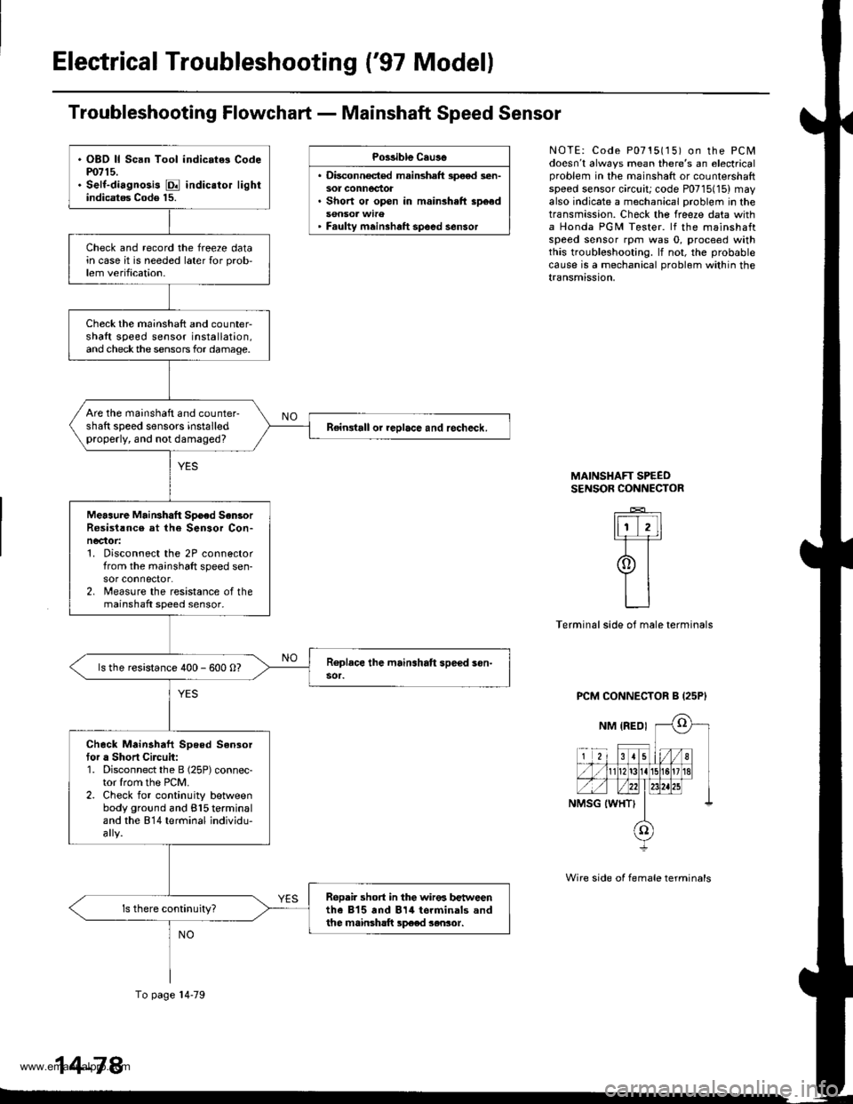
Electrical Troubleshooting {'97 Model)
Troubleshooting Flowchart - Mainshaft Speed Sensor
Po$ible Cau3o
. Disconnocted mainshaft speod sen-sot connectot. Short or open in mainsh.ft sp6ed
' Faulty meinshaft spoed sensor
NOTE: Code P0715115) on the PCMdoesn't always mean there's an electricalproblem in the mainshaft or counlersharlspeed sensor circuit; code P0715(15) mayalso indicate a mechanical problem in thetransmission. Check the freeze data witha Honda PGM Tester. lf the mainshaftspeed sensor rpm was 0, proceed withthis troubleshooting. lf not, the probablecause is a mechanical problom within thetransmission,
MAINSHAFT SPEEOSENSOR CONNECTOR
_E_
ItiT,ll-F=r
9t
LJ
Terminal side of male terminals
PCM CONNECTOR B {25P'
Wire side of female terminals
. OBD ll Scan Tool indic.t6 Codem715.. Self-diagnosis E indic.tor lightindicatag Code 15.
Check and record the freeze datain case it is needed later {or prob,lem verification.
Check the mainshaft and counter-shaft speed sensor installation,and checkthe sensors for damage.
Are the mainshaft and counter-shaft speed sensors installedproperly, and not damaged?Reingtall or reolace and recheck.
Meaaure MaiNhatt Spoed Sen3orR6sist!nce at the Sensor Con-necaor:1. Disconnect the 2P connectorfrom the mainshaft speed sen-sor connector.2. lreasure the resistance of themainshaft speed sensor.
ls the resistance 400 - 600 O?
Check Mainahaft Speed Sensortor a Short Circuit:1. Disconnect the B (25P) connec-tor lrom the PCM.2. Check for continuity betlveenbody ground and 815 terminaland the 814 terminal individu-
ReDair short in the wir€6 b€t reenthe 815 and 814 torminals andthe mainsh!ft sp€ed sensor.
To page l4-79
14-78
www.emanualpro.com
Page 630 of 1395
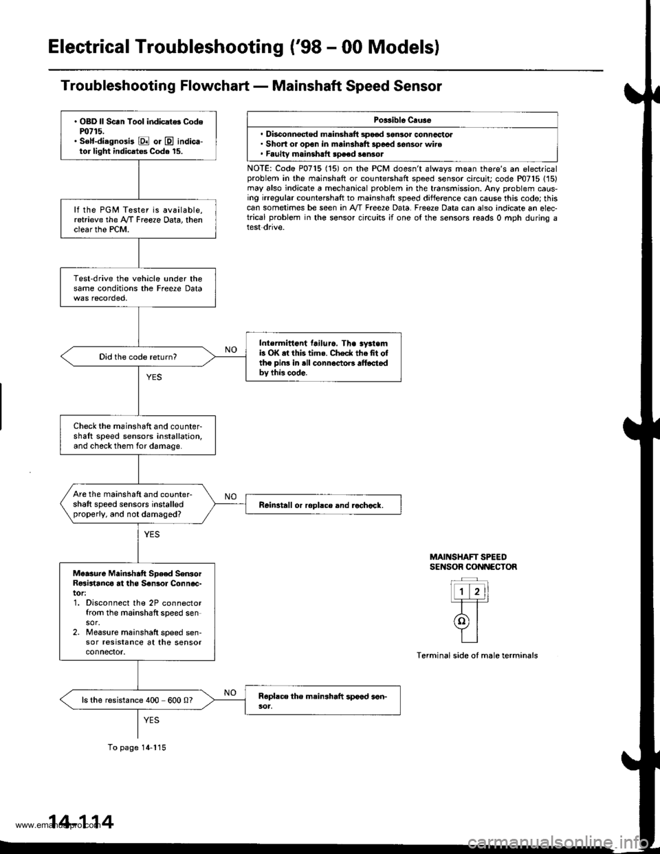
Electrical Troubleshooting ('98 - 00 Modelsl
Troubleshooting Flowchart - Mainshaft Speed Sensor
Porsible Cruse
. Disconnsct€d msinsh.ft 3pood 3gnlor conncctol. Short or open in mainshaft 3poed sensor wire. Faultv mainshrtt speed sonsot
NOTE: Codo P0715 (15) on the PCM doesn't always moan there's an electricalproblem in the mainshaft or countershaft speed sensor circuit; code P07'15 (15)may also indicate a mechanical problem in the transmission. Any problem caus-ing irregular countershaft to mainshaft spoed difference can cause this codo; thiscan sometimes be seen in A'/T Free2e Data. Freeze Data can also indicate an elec-trical problem in the sensor circuits ;f one of the sensors reads 0 mph during atest dnve.
MAINSHAFT SPEEDSENSOR CONNECTOR
Terminal side of male terminals
. OBD ll Scan Tool indicat$ Codem715.. S€lf-diagnosi3 E or @ indica-tor light indicatos Code 15.
lf the PGM Tester is available,retrieve the A/f Freeze Data, thenclear the PCM.
Test-drive the vehicle under thesame conditions the Freere Data
Intermittont tailuro. Tha sy3temb OK at this tims. Check thefit oftho pins in .ll connoctoB alt6ctedbv this code.
Did the code return?
Check the mainshaft and counter-shaft speed sensors installation,and check them for damage.
Are the mainshaft and counter-shaft speed sensors installedproperly, and not damaged?Reinstall or ropllce and rochock.
Moasure Mainshatt Spe€d SenrorR€sirtanco at ths S€nsol Connoc-tor:1. Disconnect the 2P connectorfrom the mainshaft speed sensor.2. Measure mainshatt speed sen-sor resrstance at the sensorconnefior.
ls the resistance 400 600 0?
To page 14-115
14-114
www.emanualpro.com
Page 669 of 1395
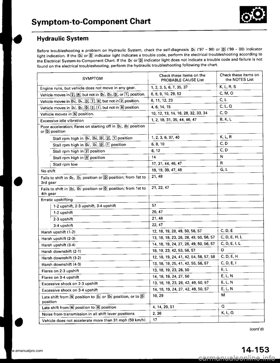
Symptom-to-Component Chart
Hydraulic System
Before troubleshooting a problem on Hydraulic system, check the self-diagnosis Dl ('97 - 98) or Lq ('99 - 00) indicator
light indication. lf the El or E indicator light indicates a trouble code, perform the electrical troubleshooting according to
the Electrical System-to-Component Chart. lf the Ol or E indicator light does not indicate a trouble code and failure is not
found on the electrical troubleshooting, perform the hydraulic troubleshooting following the chart.
SYMPTOMCheck these items on the
PROBABLE CAUSE List
Check these items on
the NOTES List
Engine runs, but vehicle does not move in any gear.1r2FAt?82?K,L.R,S
Vehicle moves in El. @, but not in lE. E, E, or E, position6, 8, 9, 10, 29, 52c,M,o
Vehicle moves in [D!. E, E. E, E, but not in E] position.al
Vehicle moves in .&1, E. E, E, E, but not in E position4,6, 14, 15c,L.o
Vehicle moves in E position.10 , 12, 13, '�l4, '16, 2A, 32, 33, 34
Excessive idle vibration1,2, 18,3'1,35, 44, 46, 41B,K,L
Poor acceleration; flares on starting off in E, Di position
or E position
Stall rpm hish in El, El, E, E, E Position
Stall rpm hiqh in E, E, E, E position
1,2,3,6,37, 40K,L,R
6, 8, 10C,D
Stall rpm high in E positionc,D
Stall rpm high in hl position14N
Stall rpm low17,31, 44, 46, 47R
No shift18, 19, 39, 47, 48G,L
Fails to shift in Pr, E position or E position; from 1st to
3rd gear
21, 48
Fails to shift in EJ, E position or E position; from 1st to
4th gear
21,22, 47
Erratic upshifting
fz upshlft. ,3 ripshlft, 3r. up+ilft57
ffi20, 47
il21, 4A
3-4 upshift22, 47
Harsh upshift ('l-2)12, 18, 19,2A,49, 50, 56, 57
Harsh upshift (2-3)13, 1A, 19,23,26,28, 49, 50, 56, 57C,D.E,H,L
Harsh upshift {3-4)14,1A, 19,24,27,28, 49, 50, 56. 57C, D, E, I,L
Harsh downshitt (2-1)18, 19,23, 42,53,56,51o
Harsh downshift (3-2)12, 18,19,24,41,42, 54. 56, 57, 58
Harsh downshift (4-3)13,'1A, 19, 25, 41, 42, 55, 56, 57C, D, E, I
Flares on 2-3 upshift13,1A,19,23,26,50FI
Flares on 3-4 upshift14, 1A, 19,24,27,50E,L,N
Excessive shock on 2-3 upshift13. '18, 19 , 23, 26, 42, 49 , 50, 51E.L.N
Excessive shock on 3-4 upshift14, 1A, 19,24,27 , 42, 49,50,51E,L,N
Late shift from N position to ld or Erl position. or to E
position
10, 29M
Late shift from E position to E position4, 14,20,51o
Noise from transmission in all shift lever positions2,36K,L.O
Vehicle does not accelerate more than 3l mph (50 km/h).11
(cont'd)
14-153
www.emanualpro.com
Page 800 of 1395
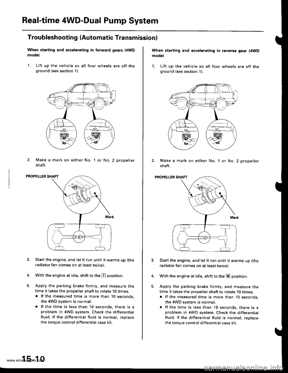
Real-time 4WD-Dual Pump System
Troubleshooting (Automatic Transmissionl
When starting and accelerating in forward gesrs {4WDmodel
1. Lift up the vehicle so all four wheels are off theground (see section 1).
2. Make a mark on either No.
shaft.
'I or No.2 propeller
PROPELLER SHAFT
Start the engine, and let it run until it warms up (the
radiator fan comes on at least twice).
With the engine at idle. shift to the E position.
Apply the parking brake firmly. and measure thetime it takes the propeller shaft to rotate 10 times.. lf the measured time is more than 10 seconds,
the 4WD system is normal.
. lf the time is less than 10 seconds, there is aproblem in 4WD system. Check the differential
fluid. lf the differential fluid is normal, replace
the torque control differential case kit.
15-10
When starting and accelerating in revGrsg gear {4WDmodel
1. Lift up the vehicle so all four wheels are off theground (see section 1).
Make a mark on either No.
shaft.
1 or No. 2 propeller
PROPELLER SHAFT
Start the engine. and let it run until it warms up (the
radiator fan comes on at least twicei.
With the engine at idle, shift to the E position.
Apply the parking brake firmly, and measure the
time it takes the proDeller shaft to rotate 10 times,. lf the measured time is more than 10 seconds,
the 4WD system js normal.. lf the time is less than 10 seconds, there is aproblem in 4WD system. Check the differential
fluid. lf the differential fluid is normal, reolace
the torque control differential case kit.
www.emanualpro.com
Page 801 of 1395
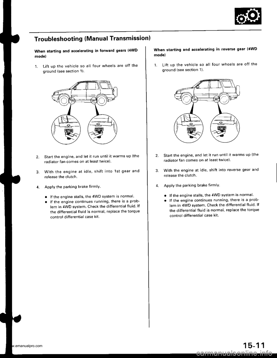
Troubleshooting (Manual Transmissionl
When starting and accelerating in forward gears (4WD
mode)
1. Lift up the vehicle so all four wheels are off the
ground {see section 1)
3.
Start the engine, and let it run until it warms up (the
radiator fan comes on at least twlce).
With the engine at idle, shift into 1st gear and
release the clutch.
Apply the parking brake firmlY
. lf the engine stalls, the 4WD system is normal.
. lf the engine continues running, there is a prob-
lem in 4WD system. Check the differential fluid. lf
the differential fluid is normal, replace the torque
control ditferential case kit.
2.
When starting and accelerating in reverse gear (4WD
model
1. Lift up the vehicle so all four wheels are off the
ground (see section 1).
Start the engine, and let it run until it warms up (the
radiator fan comes on at least twice)
With the engine at idle, shift into reverse gear and
release the clutch.
Apply the parking brake firmlY
. lf the engine stalls, the 4WD system is normal.
. lf the engine continues running, there is a prob-
lem in 4WD system. Check the differential fluid lf
the differential fluid is normal, replace the torque
control differential case kit.
3.
www.emanualpro.com
Page 802 of 1395
Real-time 4WD-Dual Pump System
Troubleshooting (Automatic Transmission/Manual Transmission)
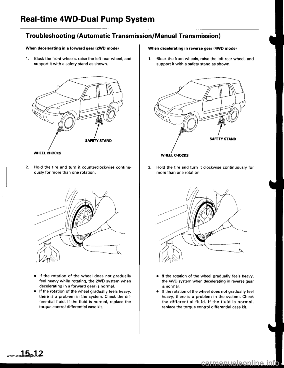
Whon d6c6l6rating in a torward gear {2WD mode}
1. Block the front wheels, raise the left rear wheel. and
support it with a safety stand as shown.
Hold the tire and turn it counterclockwise continu-
ouslv for more than one rotation.
lf the rotation of the wheel does not gradually
feel heavy while rotating, the 2WD system when
decelerating in a forward gear is normal.
lf the rotation of the wheel gradually feels heavy,
there is a problem in the system. Check the dif-
ferential fluid, lf the fluid is normal, reDlace the
toroue control differential case kit.
WHEEL CHOCKS
15-12
When decelerating in reverse gear (4WD mod€)
1. Block the front wheels. raise the left rear wheel, and
suppo( it with a safety stand as shown.
Hold the tire and turn it clockwise continuouslv for
more than one rotation.
lf the rotation of the wheel gradually feels heaw.
the 4WD system when decelerating in reverse gear
is normal,
lf the rotation of the wheel does not gradually feel
heavy, there is a problem in the system. Check
the differential fluid. lf the fluid is normal.
reolace the torque control differential case kit,
WHEEL CHOCKS
www.emanualpro.com
Page 1161 of 1395

Body Electrical
Speciaf Toofs ,...,..,.............-.23-2
Troubleshooting
Tips and Precautions ......,.,..........,.................. 23-3
Five-step Troubleshooting ........,.,.,...,,.,......... 23-5
Wire Color Codes ...,....,.. 23-5
Relay and Control Unit Locations
Engine Compartment ..,.,......,......................... 23-6
Dashboard ,.,.,..............-.- 23-7
Door ....................... .........23-10
Index to Cilcuits and Sysiems
Accessory Socket .. ,....,.,..,.,. 23-95*Airbags ................ .,....,. Sestion 24
Air Conditioning ,.,.,.... Section 22
Alternator ................... Section 4
Anti-lock Brake System {ABSI ................... Section 19'A/T Gear Position Indicator ....................... Section 1,1
Automatic Transmission System ...........,.. Section 14
Battery ................... ..............23-50
Blower Controls .,...,.,, Section 22
Charging System ....... Seqtion il
Clock -'98 Model ................ 23-98
Connector ldentification and Wire HarnessRouting .................. ......... 23.11
Cruise Control ............ Ssction 4
Dash Lights Brightness Contlo||er ..................... 23-90
Fan Conlrols ...,......,.... Section 10
Fuel Pump ,..,.,...,....,.... Section 11
Fuses...................... .,,.,.,.,.,,.,23-40*Gauges
Circuit Diagram ......-....-..23-58
Fuel Gauge .....,.,..... Section 11
Speedometer ..,..........,... 23-56
Ground Distribution ,....,.,...23-46
Hatch Glsss ODenor .........................,.,.,.,.,..,.,.,.,,. 23-121
Heater Controls .-........ Soction 21*Horns.,...,..,.,.,....... ................23"104*fgnition Switch ,,.,.,..,.,.,,.,.,.,23-51
lgnition Key Light System -'97 Mod6l .............. 23.88
-+
BODY
www.emanualpro.com