windows HONDA CR-V 1999 RD1-RD3 / 1.G Workshop Manual
[x] Cancel search | Manufacturer: HONDA, Model Year: 1999, Model line: CR-V, Model: HONDA CR-V 1999 RD1-RD3 / 1.GPages: 1395, PDF Size: 35.62 MB
Page 1016 of 1395
22.
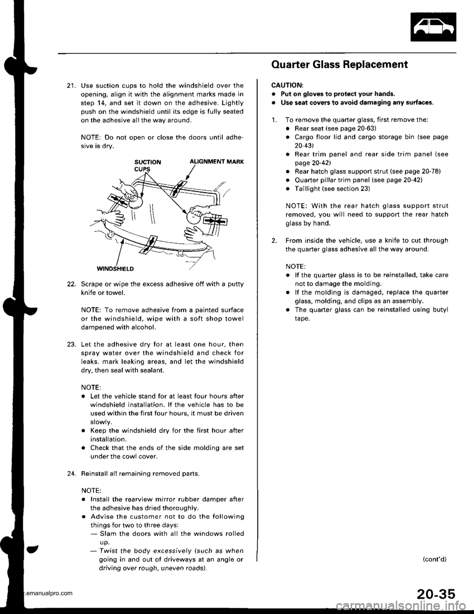
21. Use suction cups to hold the windshield over the
opening, align it with the alignment marks made in
step 14, and set it down on the adhesive. Ljghtly
push on the windshield until its edge is fully seated
on the adhesive all the way around.
NOTEr Do not open or close the doors until adhe-
sive is dry.
SUCTTON ALIGNMENT MARK
Scrape or wipe the excess adhesive off with a putty
knife or towel.
NOTE: To remove adhesive from a painted surface
or the windshield, wipe with a soft shop towel
dampened with alcohol.
Let the adhesive dry for at least one hour, then
spray water over the windshield and check for
leaks. mark leaking areas, and let the windshield
dry, then seal with sealant.
NOTE:
. Let the vehicle stand for at least four hours after
windshield installation. lf the vehicle has to be
used within the first four hours, it must be driven
. Keep the windshield dry for the first hour after
installation.
. Check that the ends of the side molding are set
under the cowl cover.
Reinstall all remaining removed parts.
NOTE:
. Install the rearview mirror rubber damper after
the adhesive has dried thoroughl,.
. Advise the customer not to do the following
things for two to three days:- Slam the doors with all the windows rolled
up.- Twist the body excess,vely {such as when
going in and out of driveways at an angle or
driving over rough. uneven roads).
24.
Ouarter Glass Replacement
CAUTION:
. Put on gloves to prot€ct your hands.
. Use seat covers to avoid damaging any surfaces.
1. To remove the quarter glass, first remove the:
. Rear seat (see page 20-63)
. Cargo floor lid and cargo storage bin (see page
20 431
. Rear trim panel and rear side trim panel (see
page 20-421
. Rear hatch glass support strut (see page 20-78)
. Ouarter pillar trim panel (see page20-421
. Taillight (see section 23)
NOTE: With the rear hatch glass support strut
removed, you will need to support the rear hatch
glass by hand.
2. From inside the vehicle, use a knife to cut through
the quarter glass adhesive all the way around.
NOTE:
. lf the quaner glass is to be reinstalled, take care
not to damage the molding.
. lf the molding is damaged. replace the quarter
glass, molding, and clips as an assembly.
. The quarter glass can be reinstalled using butyl
tape.
(cont'd)
20-35
www.emanualpro.com
Page 1020 of 1395
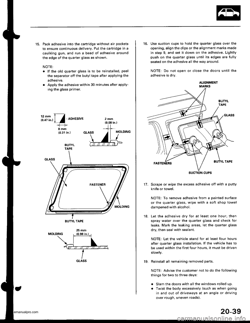
15. Pack adhesive into the cartridge without air pockets
to ensure continuous delivery, Put the canridge in a
caulking gun, and run a bead of adhesive around
the edge of the quarter glass as shown.
NOTE:
. lf the old quarter glass is to be reinstalled, peel
the separator off the butyl tape after applying the
adhesive.
. Apply the adhesive within 30 minutes after apply-
ing the glass primer.
i:.8T".,1,/:AoHEsrvE
I rnm(0.31 in.)
BUTYLTAPE
GLASS19.
20-39
16. Use suction cups to hold the quarter glass over the
opening, align the clips or the alignment marks made
in step 9, and set it down on the adhesive. Lightly
push on the quaner glass until its edges are fully
seated on the adhesive all the way around.
NOTE: Do not open or close the doors until the
adhesive is drv.
Scrape or wipe the excess adhesive off with a putty
knife or towel,
NOTE: To remove adhesive from a painted surface
or the quarter glass, wipe with a soft shop towel
dampened with alcohol.
Let the adhesive dry for at least one hour. then
spray water over the quarter glass and check for
leaks. Mark the leaking areas, let the quarter glass
dry, then seal with sealant.
NOTE: Let the vehicle stand for at least four hours
after quarter glass installation. lf the vehicle has to
be used within the first four hours, it must be driven
slowly.
Reinstall all remaining removed parts.
NOTE: Advise the customer not to do the following
things for two to three days:
. Slam the doors with all the windows rolled up.
. Twist the body excessively (such as when going
in and out of driveways at an angle or driving
over rough, uneven roads).
11.
18.
AUGNMENT
SUCTION CUPS
www.emanualpro.com
Page 1292 of 1395
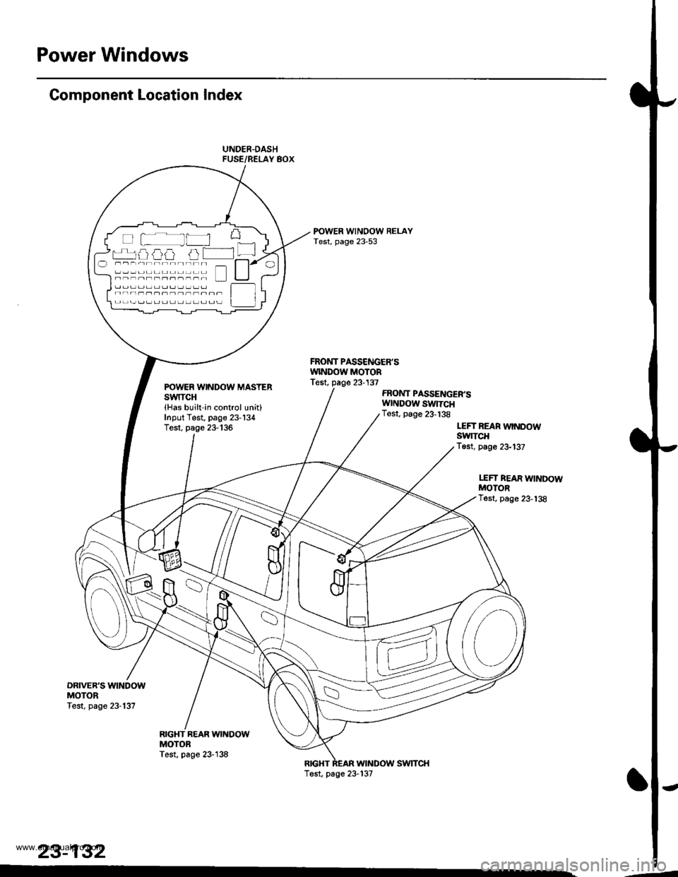
Power Windows
Component Location Index
FRONT PASSCNGER'SWINDOW MOTORTest, page 23-137POWER WINDOW MASTERSWITCH(Has built in control unit)Input Test, page 23-'134Test, page 23-135
RIGHT REAR WINDOWMOTOBTest. page 23-138
FBOI{T PASSENGER'SWI{DOW SWTTCHTest, page 23-138
LEFT REAN WWDOWSwlTCHTest, page 23-137
LEFT REAR WINDOWMOTORTest, page 23-'t38
DRIVER'S WINDOWMOTORTest, page 23-137
RIGHTwtNDow swTcHT6sr, page 23-137
tt
L--JIJJ'JJL J 1J 15-- --------------) ------------ t_.1
--.-\-.--t
\-
23-132
.-
www.emanualpro.com
Page 1294 of 1395
Power Windows
Master Switch Input Test
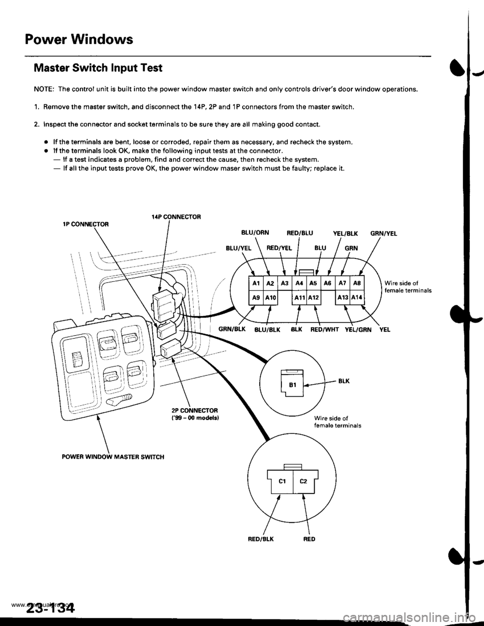
NOTE: The control unit is built into the power window master switch and only controls driver's door window operations.
1. Remove the master switch, and disconnect the 14P,2? and 1P connectors from the master switch.
2. Inspect the connector and socket terminals to be sure they are all making good contact.
. lf the terminals are bent, loose or corroded, repair them as necessary, and recheck the system,
. lf the terminals look OK, make the following input tests at the connector.- lf a test indicates a problem, find and correct the cause, then recheck the system.- lf all the input tests prove OK, the power window maser switch must be faulty; replace it.
1P CONNECTOR
BLU/ORN RED/BLUYEL/BLK
BLU/YEL RED/YELGRN
GRN/YEL
POWER WINDOW MASTEB SWITCH
GRN/BLK aLu/BLK BLK RED/WHT YEL/GRN YEL
Wire side offemale terminals
RED/BLK
lirP CONNECTOR
23-134
Wire side oIfemale terminals
.-
www.emanualpro.com
Page 1296 of 1395
Power Windows
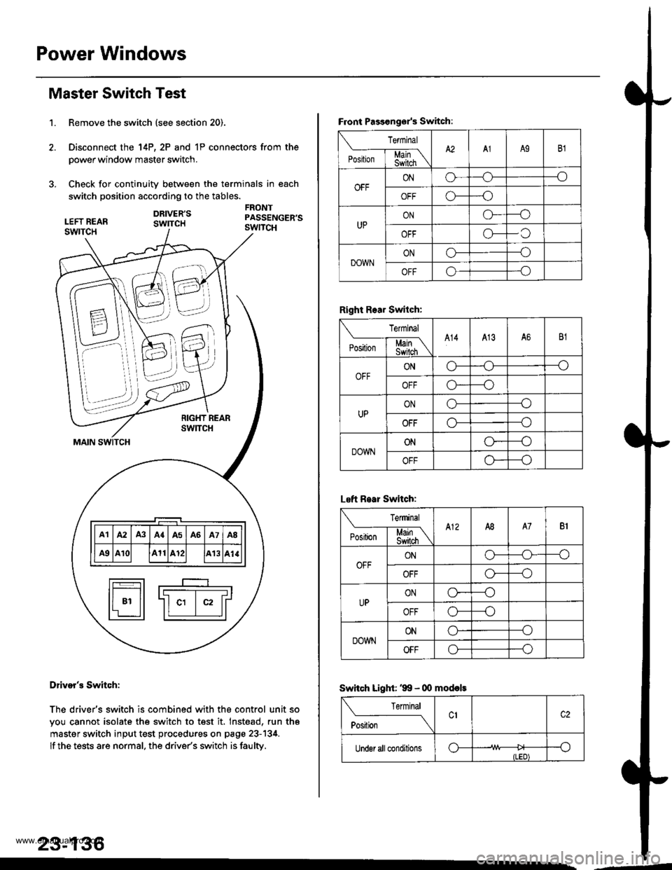
1.
Master Switch Test
Remove the switch (see section 20).
Disconnect the 14P, 2P and 1P connectors from the
power window master switch.
Check for continuity between the terminals in each
switch position according to the tables.
DRIVER'SswrTcH
FRONTPASSENGER'SswncH
B \\N
7-.i::,,,
\\'. )),,
t-_____r-__I F---T-----r-----r----r-----T---------T-----'r Illal lA2 lA3 lA{lA5 lA6 lA7 laB ll
lF#lll ae lA10l lA11lA12l lA13lal.llI r________r_____J t-t___Jl
fr---r-l r----
I t-------- -------r l
ll 81 ll -ll c1 | c2 lrl'r ll ll I llL--:J
Dliver's Switch:
The driver's switch is combined with the control unit so
you cannot isolate the switch to test it. Inst€ad, run th6
master switch input test procedures on page 23-134.
lf the tests are normal. the drive/s switch is faulty.
23-136
--d
F.ont Passongsr's Switch:
rermrnal
'**[ffiA2A1A9B1
OFFONo--_o
o---o
UPONG---o
OFFo-C
DOWNONo---o
OFFo---o
Right Rear Switch:
Terminal
'".'*l-$j[\A14413A6B1
OFFONo---o
OFFo*--o
UPONo---o
OFFo---o
DOWNONo----o
OFFo---o
Left R.ar Switch:
Terminal
e*Li*l$[\A12A8A7B1
OFFONo-o--o
OFFo---o
UPONo----o
OFFo---o
DOWNONo--_o
OFFo---o
Swhch Light: '99 - 00 mod€ls
Terminal
ti.*----_\
Under all conditionso--o
ILED)
www.emanualpro.com
Page 1298 of 1395
Power Windows
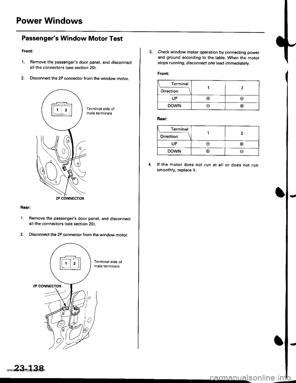
Passenger's Window Motor Test
Front:
l. Remove the passenger's door panel, and disconnect
allthe connectors (see section 20).
2. Disconnect the 2P connector from the window motor.
Rear:
1. Remove the passenger's doo. panel, and disconnect
allthe connectors (see section 20).
2. Disconnectthe 2P connectorfrom the window motor.
23-138
3. Check window motor operation by connecting power
and ground according to the table. When the motor
stops running, disconnect ohe lead immediatelv.
Front:
Terminal
;."b"
.l\
UP@
DOWNo@
R€ar:
I Terminal
;*r*
-l\
UPo@
DOWN@o
lf the motor does not run at all or does not runsmoothly, replace it.
www.emanualpro.com