Air Control HONDA CR-V 2000 RD1-RD3 / 1.G Workshop Manual
[x] Cancel search | Manufacturer: HONDA, Model Year: 2000, Model line: CR-V, Model: HONDA CR-V 2000 RD1-RD3 / 1.GPages: 1395, PDF Size: 35.62 MB
Page 789 of 1395
Replacement
SRS components are located in this area. Review the SRS
component locations, precautions, and procedures in the
SRS section {24} before performing repairs or service.
1. Remove the instrument panel lower cover and the
column covers (see section 17).
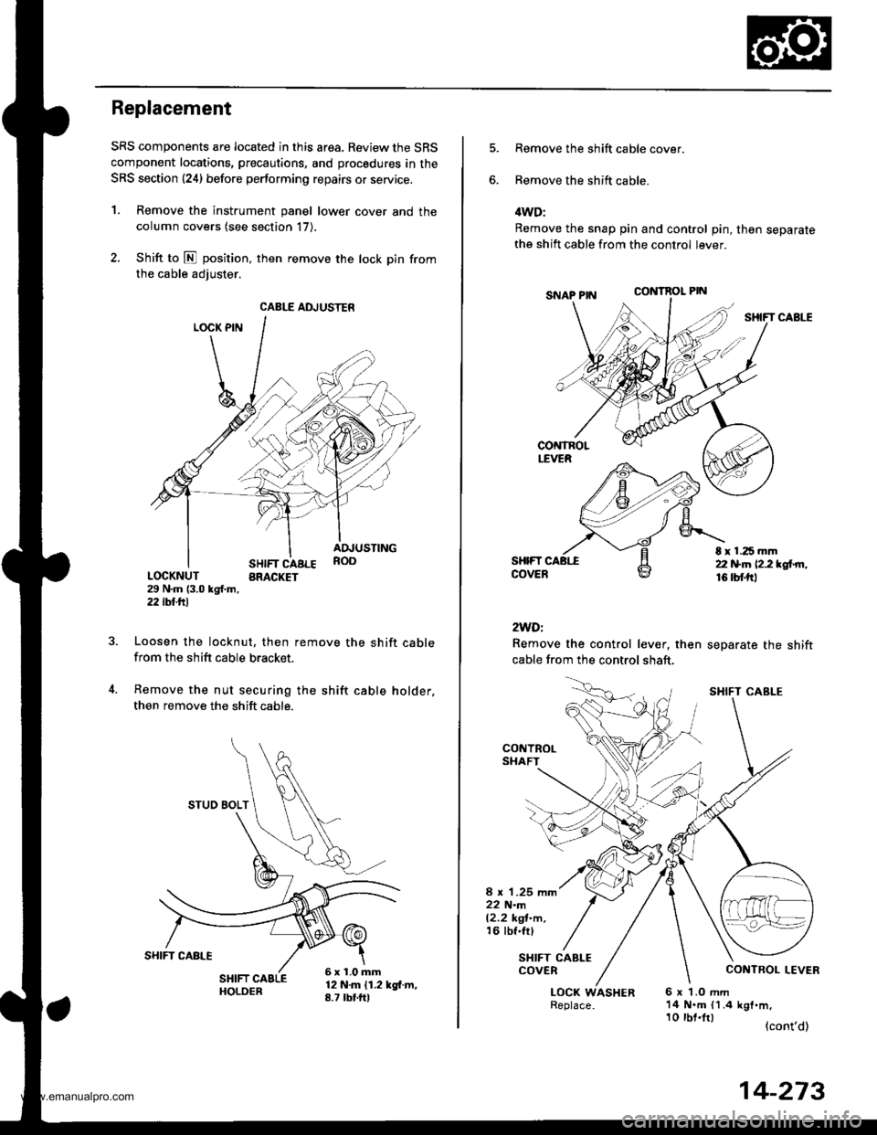
2. Shift to E position, then remove the lock pin from
the cable adiuster.
LOCK PIN
SHIFT CABLEBRACKET
ADJUSTINGROO
LOCKNUT29 N.m {3.0 kgl.m,2j2lbf.trl
Loosen the locknut, then remove the shift cablefrom the shift cable bracket.
Remove the nut securing the shift cable holder,
then remove the shift cable.
12 N.m {1.2 kgf.m,8.7 tbtfrl
CABLE ADJUSTER
STUO BOLT
6x1.0mm
Remove the shift cable cover.
Remove the shift cable.
4WD:
Remove the snap pin and control pin, then separatethe shift cable from the control lever.
CONTROL PIN
SHIFT CABLE
SHIFTCOVER
2WDi
Remove the control lever, then
cable from the control shaft.
separate the shift
t r 1.25 mm22 N.n 12.2 *glrn.16 tbf.trl
CONTROLSHAFT
8 x 1.25 mm22 N.m12.2 kgl-m,16 tbf.frl
SHIFT CABLECOVER
LOCK WASHER6x LOmm14 N.m {1.4 kgf.m,
(cont'd)
SHIFT CABI-E
10 tbt.lrl
14-273
www.emanualpro.com
Page 849 of 1395
Troubleshooting
General Troubleshootin g
Check the following before you begin:
. Has the suspension been modified in a way that would affect steering?
. Are tire sizes, tire variety and air pressure correct?
. ls the steering wheel original equipment or equivalent?
. ls the power steering pump belt properly adjusted?
. ls steering fluid reservoir filled to proper level?
. ls the engine idle speed correct and steady?
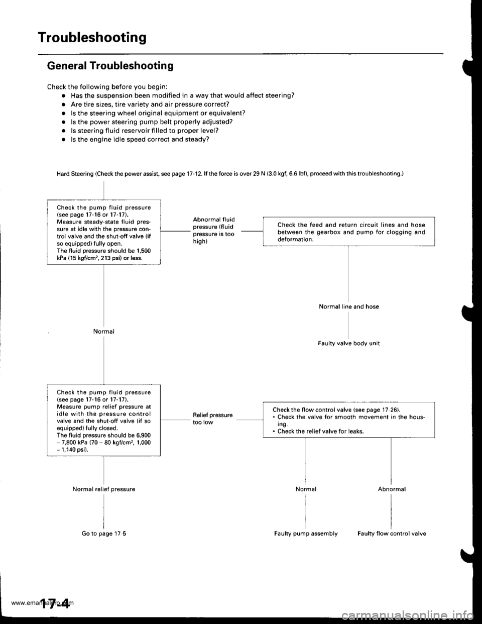
Hard Steering (Check the power assist, see page 17-12. lf the force is over 29 N (3.0 kgl 6.6 lbfl, proceed with this troubleshooting.i
Abnormalthiidpressure (Iluidpressure is toohigh)
Relief pressuretoo low
Faulty valve body unit
Abnormal
Check the teed and return circuit lines and hosebetween the gearbox and pump for clogging anddeformation.
Normal line and hose
Check the pump fluid pressure(see page 17-16 or 17-17).Measure steady state lluid pres-
sure at idle with the pressure con-trol valve and the shut-off valve (it
so equipped) fully open.The fluid pressure should be 1,500kPa (15 kgf/cm,,213 psi)or less.
Normal
Check the flow control valve (see page 17 26).. Check the valv€ lor smooth movement in the hous-ing.. Check the relief valve for leaks.
Check the pump fluid pressure(see page 17-16 or l7-17).Measure pump relief pressure atidle with the pressure controlvalve and the shut'off valve lil soequipped) fully closed.The fluid pressure should be 6,9007,800 kPa (70 - 80 kgflcm,, 1,000- 1,140 psi).
Normal relief pressure
17-4
Go to page 17 5Faulty pump assemblyFaulty flow control valve
www.emanualpro.com
Page 852 of 1395
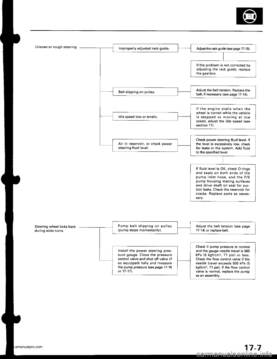
Uneven or rough steering.Ad,ust the rack gu ide (see page 17- 15).
ll the problem is not corrected byadjusting the rack guide, replacethe gearbox.
Adjust the belttension. Replace thebelt, if necessary (see page 17-14).Belt slipping on pulley.
lf the engine stalls when thewheel is turned while the vehicleis stopped or moving at lowspeed, adjust the idle speed (seesection 111.
ldle speed low or erratic.
Check power steering lluid level. lfthe level is excessively low checkfor leaks in the system. Add fluidto the specified level.
Air in reservoir, or check powersteering tluid level.
lf fluid level is OK, check O-ringsand seals on both ends of thepump inlet hose, and the P/Spump housing mating surlacesand drive shaft oil seal for suction leaks. Check the reservoir forcracks, Replace parts as neces-
Pump belt slipping on pulley(pump stops momentarily).Adjust the belt tension (see page17-14) or replace belt.
Check if pump pressure is normaland the gauge needle travel is 500kPa (5 kgl/cm,, 71 psi) or less.Check the flow control valve if theneedle travel exceeds 500 kPa (5kgflcm'�, 71 psi). lI the flow controlvalve is normal, replace the pumpas an assembly,
Install the power steering pres-sure gauge, Close the pressurecontrol valve and shut off valve (if
so equipped) fully and measurethe pump pressure (see page 17-16ot 17 17).
Steering wheel kicks backduring wide turns.
7-7
www.emanualpro.com
Page 861 of 1395
lnspection and Adjustment
Pump Pressure Gheck With T/N 07406 - 0010001
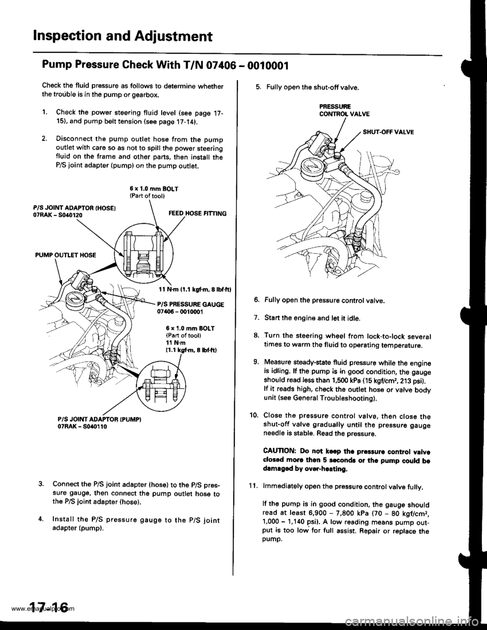
Check the fluid pressure as follows to determine whetherthe trouble is in the pump orgearbox.
1. Check the powsr steering fluid level (see page 17-15), and pump belt tension (see page 17-14).
2. Disconnect the pump outlet hose from the pump
outlet with care so as not to spill the pow€r steeringiluid on the frame and other pans. thon install theP/S joint adapter (pumpl on the pump outlet.
6 x 1.0 mm BOLT{Part oftool)
FEED HOSE FITTING
PUMP OUTLET HOSE
11 N.m ll.1 kgl.m, E lbf.ftl
P/S PRESSURE GAUGE07('6 - 0010001
6 x t.0 mm BOLT{Part oftool)11 N.m(1.1 kgt m, 8 lbf.tr)
Connect the P/S joint adapter (hose) to the p/S pres-
sure gauge, then connect the pump outlet hose tothe P/S ioint adspter (hose).
Install the P/S pressure gauge to the p/S joint
adapter (pump),
17-16
5. Fully open the shut-off valve.
PRESSURECONTROL VALVE
6. Fully open the pressure controlvatve.
7. Start the engine and let it idle.
8. Turn the steering wheel from lock-to-lock severaltimes to warm the fluid to operating temperature.
9, Measure steady-state fluid pressure while the engineis idling. lf the pump is in good condition, the gauge
should read less than 1,500 kPa (15 kgf/cmr, 213 psi).
lf it reads high, check the outlet hose or valve bodvunit (see General Troubleshooting).
10. Close the pressure control valve, then close theshut-off valve gradually until the pressure gauge
nsedle is stable. Read the pressure.
CAUTION: Do not k€ap tha prca3un control valvoclorod mo.c thon 5 srconds or thc pump cluld bodamEgod by ovor-hoating.
11. lmmodiately open the pressure controlvalve fullv.
lf the pump is in good condition, the gauge shouldread at least 6,900 - 7,800 kpa (70 - 80 kgflcmr,'1,000 - 1.140 psi). A low reading means pump out-put is too low for full assist. Repair or replace theDUMD.
www.emanualpro.com
Page 862 of 1395
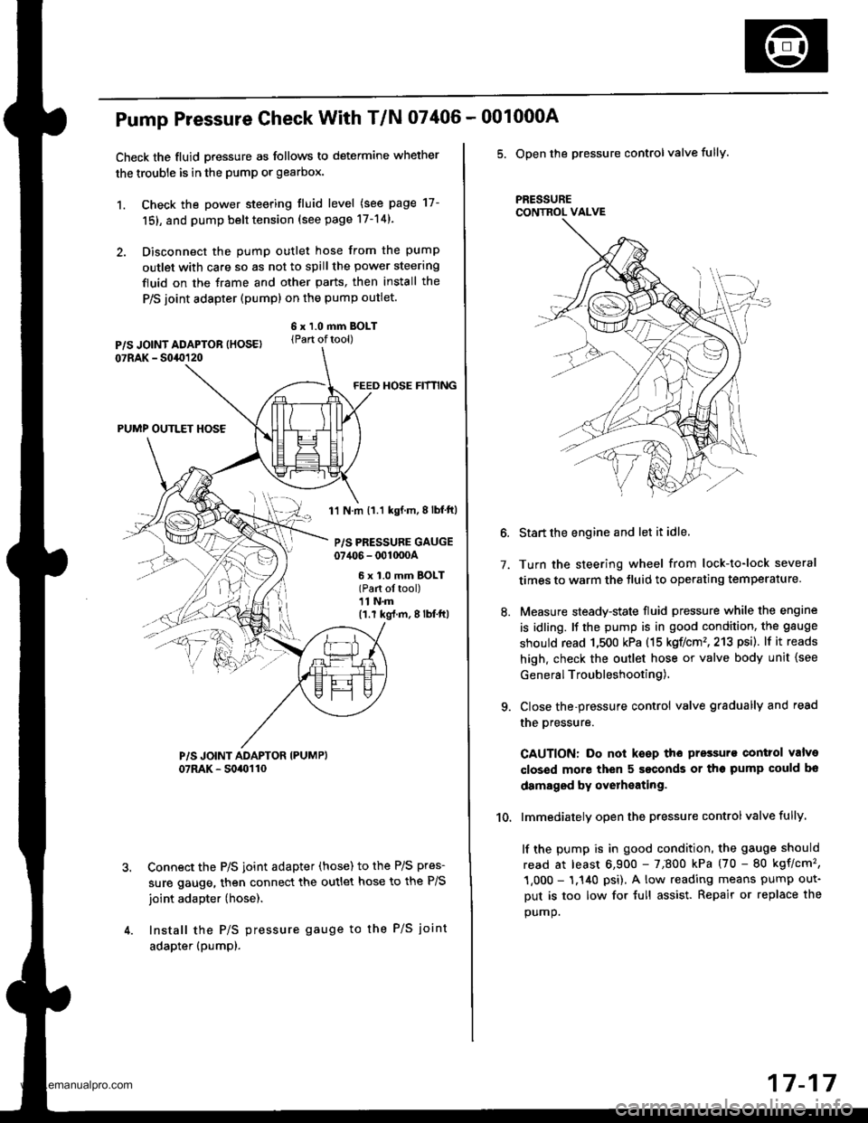
Pump Pressure Check With T/N 07406 -
Check the fluid pressure as follows to determine whether
the trouble is in the pump or gearbox.
1. Check the power steering tluid level (see page 17-
151, and pump belt tension (see page 17-14).
2. Disconnect the pump outlet hose from the pump
outlet with care so as not to spill the power steering
fluid on the frame and other parts, then install the
P/S joint adapter (pump) on the pump outlet.
6 x 1.0 mm BOLT(Part oftool)
FEED HOSE HfNNG
PUMP OUTLET HOSE
1'l N.m 11.1 kgf.m,8lbf ft)
P/S PRESSURE GAUGE07406 - 001000A
6 x 1.0 mm BOLT(Part ol tool)11 N.m(1.r kg{.m,8lbf'ft|
Connect the P/S joint adapter (hose) to the P/S pres-
sure gauge, then connect the outlet hose to the P/S
joint adapter (hose).
Install the P/S pressure gauge to the P/S joint
adapter (pumpl.
001000A
5. Open the pressure controlvalve fully.
PRESSURECONTROL VALVE
7.
10.
Start the engine and let it idle.
Turn the steering wheel from lock-to-lock several
times to warm the tluid to operating temperature.
Measure steady-state fluid pressure while the engine
is idling. It the pump is in good condition, the gauge
should read 1,500 kPa (15 koflcm'�,213 psi). lf it reads
high. check the outlet hose or valve body unit {see
General Troubleshooting),
Close the-pressure control valve gradually and read
the oressure.
CAUTION: Do not keep the pressurs control valve
closed more then 5 seconds or the pump could bo
damaged by overheating.
lmmediately open the pressure controlvalve fully.
lf the pump is in good condition, the gauge should
read at least 6,900 - 7;800 kPa (70 - 80 kgflcm'�,
1,000 - 1.140 psi), A low reading means pump out-
Dut is too low for {ull assist. Repair or replace the
oumo.
17-17
www.emanualpro.com
Page 863 of 1395
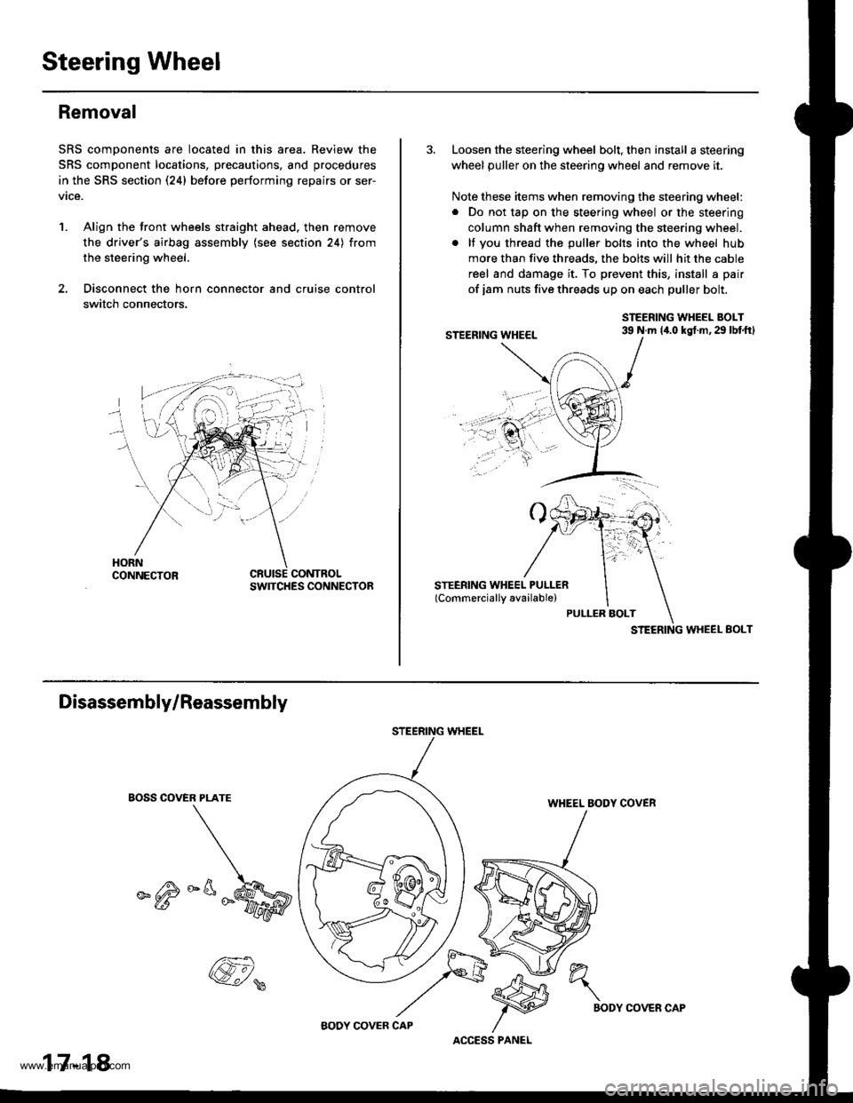
Steering Wheel
Removal
SRS components are located in this area. Review the
SRS component locations, precautions, and procedures
in the SRS section (24) before performing repairs or ser-
vice.
1. Align the front wheels straight ahead. then remove
the driver's airbag assembly (see section 24) from
the steering wheel.
2. Disconnect the horn connector and cruise control
switch connectors.
CONTROLSWITCHES CONNECTOR
3. Loosen the steering wheel bolt, then install a steering
wheel puller on the steering wheel and remove it.
Note these items when removing the steering wheel:
. Do not tap on the steering wheel or the steering
column shaft when removing the steering wheel.
. lf you thread the puller bolts into the wheel hub
more than five threads, the bolts will hit the cable
reel and damage it. To prevent this, install a pair
of jam nuts five threads up on each puller bolt.
STEERING WHEEL BOLT39 N.m 14.0 kgt.m,29 lbtftl
STEERING WHEEL EOLT
Disassembly/Reassembly
EOSS COVER PLATE
_^M
STEERING WHEEL
WHEEL BODY COVER
17-18
@,
ACCESS PANEL
h"\
BODYCOVER CAP
www.emanualpro.com
Page 864 of 1395
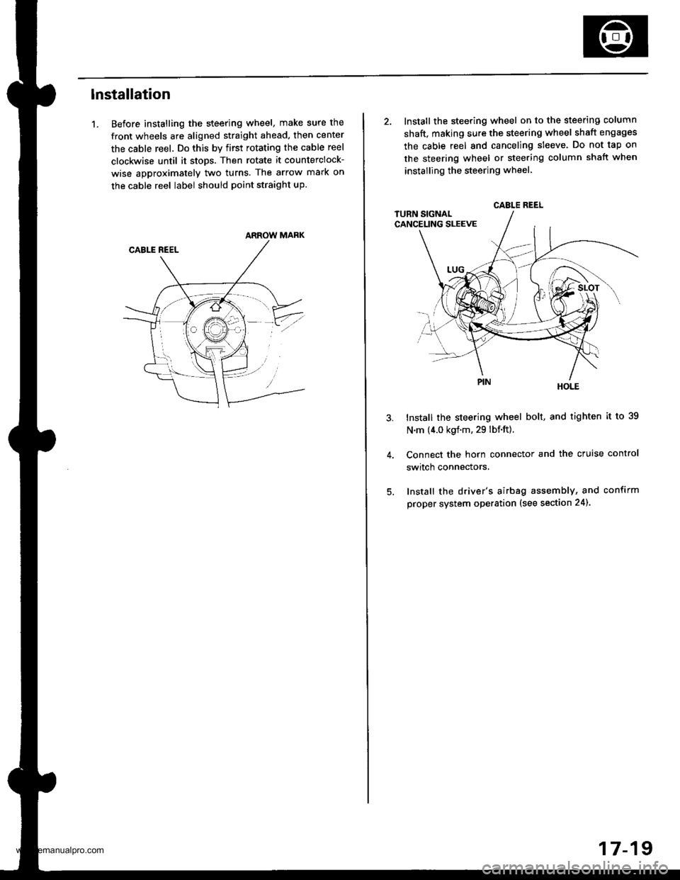
lnstallation
1. Before installing the steering wheel, make sure the
front wheels are aligned straight ahead, then center
the cable reel. Do this by first rotating the cable reel
clockwise until it stops. Then rotate it counterclock-
wise approximately two turns. The arrow mark on
the cable reel label should point straight up.
ARROW MARK
2. Install the steering wheel on to the steering column
shaft, making sure the steering wheel shaft engages
the cable reel and canceling sleeve. Do not tap on
the steering wheel or steering column shatt when
instailing the steering wheel
HOLE
Install the steering wheel bolt, and tighten it to 39
N.m (4.0 kgf.m, 29 lbf.ft).
Connect the horn connector and the cruise control
switch connectors,
Install the driver's airbag assembly, and confirm
proper system operation (see section 24).
CABLE REEL
17-19
www.emanualpro.com
Page 872 of 1395
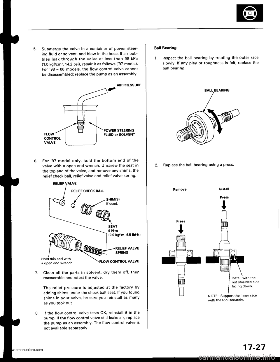
5. Submerge the valve in a container of power steer-
ing fluid or solvent, and blow in the hose. lf air bub-
bles leak through the valve at less than 98 kPa
(1.0 kgflcm'�, 14.2 psi), repair it as follows ('97 model).
For'98 - 00 models, the flow control valve cannot
be disassembled; replace the pump as an assembly
AIR PRESSURE
POWER STEENINGFLUID or SOLVENT
6.For'97 model only, hold the bottom end of the
valve with a open end wrench. Unscrew the seat in
the top end of the valve, and remove any shims, the
reliel check ball, relief valve and relief valve spring.
RELIEFALVE
RELIEF CHECK BALL
{w@r
7.
SEAT9 N.m(0.9 kgf.m, 6.5 lbfft)
RELIEF VALVESPRING
FLOW CONTBOL VALVE
Clean all the parts in solvent, dry them otf, then
reassemble and retest the valve.
The relief pressure is adjusted at the factory by
adding shims under the check ball seat lf you found
shims in your valve, be sure you reinstall as many
as you took out.
lf the flow control valve tests OK, reinstall it in the
pump. It the flow control valve still leaks air, replace
the pump as an assembly. The flow control valve is
not available separately.
8,
Hold this end witha open eno wrencn.
Ball Bearing:
'1. Inspect the ball bearing by rotating the outer race
slowly. lf any play or roughness is felt, replace the
ball bearing.
2. Replace the ball bearing using a press.
Removelnstall
Press
I
Press
I
lnstall with thered shaelded sidefacing down.
NOTEr SuPPort the inner race
with the tool securelY-
BALL EEARING
17-27
www.emanualpro.com
Page 952 of 1395
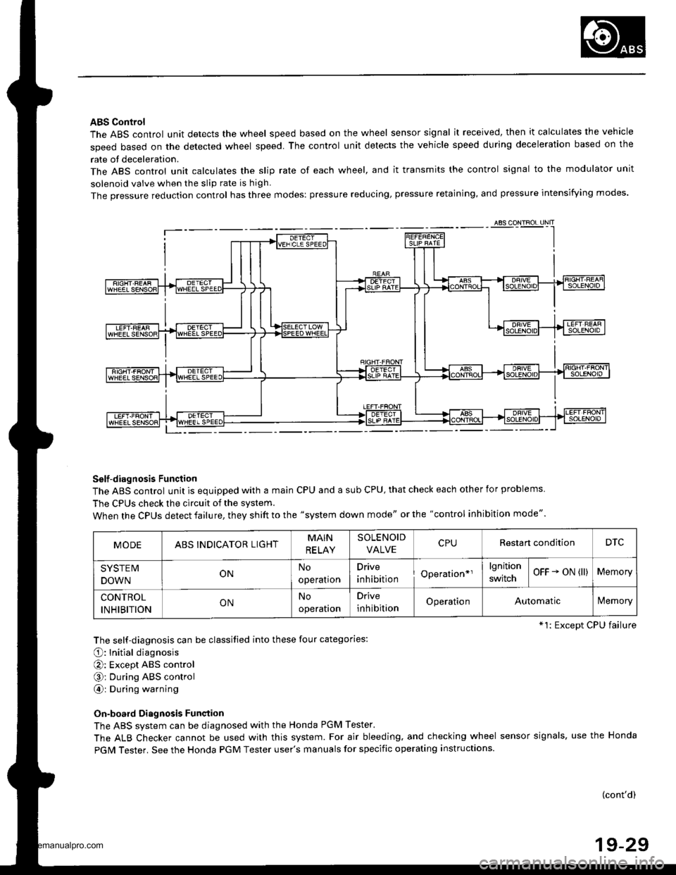
ABS Control
The ABS control unit detects the wheel speed based on the wheel sensor signal it received, then it calculates the vehicle
speed based on the detected wheel speed. The control unit detects the vehicle speed during deceleration based on the
rate of deceleration.
The ABS control unit calculates the slip rate of each wheel, and it transmits the control signal to the modulator unit
solenoid valve when the slip rate is high
The pressure reduction control has three modes: pressure reducing, pressure retaining, and pressure intensi{ying modes.
Self-diagnosis Function
The ABS control unit is equipped with a main cPU and a sub cPU, that check each other for problems.
The CPUs check the circuit of the system.
When the CPUS detect failure, they shift to the "system down mode" or the "control inhibition mode".
The self-diagnosis can be classitied into these four categories:
O: Initial diagnosis
O: Except ABS control
O; During ABS control
@: During warning
On-board Diagnosis Function
The ABS system can be diagnosed with the Honda PGM Tester.
The ALB Checker cannot be used with this system. For air bleeding. and checking wheel sensor signals, use the Honda
PGIM Tester. See the Honda PGM Tester user's manuals for specific operating instructions.
(cont'd)
19-29
ABS CONTROL I-INIT
MODEABSINDICATOR LIGHTMAIN
RE LAY
SOLENOID
VALVERestan conditionDTC
SYSTEM
DOWNONNo
operatron
Drive
inhibitionOperation*rlgnition
switchOFF - oN (ll)Memory
CONTROL
INHIBITIONONNo
operaton
Drive
inhibitionOperationAutomaticlVemory
*1: Except CPU failure
www.emanualpro.com
Page 960 of 1395
Kickback'1. The motor operates when the ABS is functioning. and the fluid in the reservoir is forced out to the master cylinder,
causing kickback at the brake pedal.
2. The ABS control unit operates the solenoid valve when the brake pedal is released after the initial diagnosis You may
hear the solenoid valve operate at this time, but it is normal
Pumo Motol
1. The pump motor operates when the ABS is functioning
2. The ABS control unit checks the pump motor operation during acceleration. You may hear the motor operate at this
time, but it is normal.
Brake Fluid Replacement/Ail Bleeding
L Brake fluid replacement and air bleeding procedures are the same as for vehicles without ABS To ease bleeding, start
with the front wheels.
Troubleshooting
1. The troubleshooting flowchart procedures assume that the cause of the problem is still present and the ABS indicator
is still on. Following the flowchart when the ABS indicator does not come on can result in incorrect diagnosis.
2. Ouestion the customer about the conditions when the problem occurred, and try to reproduce the same conditions
for troubleshooting.
Self-diagnosis is made at various times such as the initial diagnosis, except ABS control, during ABS control, during
acceleration, during the specified vehicle speed, etc. Therefore, the symptom canngt be checked unless the check
conditions match with the problem conditjons
3. When the ABS jndicator does not come on during the test-drive. but troubleshooting is performed based on the DTC,
check lor loose connectors, poor contact of the terminals, etc., before you start troubleshooting.
4. After troubleshooting, erase the DTC and test-drive the vehicle. Be sure the ABS indicator does not come on.
5. The connector illustratjons show the female terminals with a single outline and the male terminals with a double out-
l ne.
ABS Function Test
To simulate ABS operation and activate the solenoid valves and pump, use the Honda PGM Tester.
Connect the PGM Tester to the 16P Data Link Connector (DLC). When the System Select menu is displayed, select the ABS
Test Mode menu, and follow the tester's prompts.
19-37
www.emanualpro.com