Gauge HONDA CR-V 2000 RD1-RD3 / 1.G Workshop Manual
[x] Cancel search | Manufacturer: HONDA, Model Year: 2000, Model line: CR-V, Model: HONDA CR-V 2000 RD1-RD3 / 1.GPages: 1395, PDF Size: 35.62 MB
Page 1241 of 1395
Adjustment
Bstore adiusting the headlights:
. Park the vehicle on level ground
. Make sure the fuel tank is tull
. The driver or someone who weighs the same should
sit in the driver's seat.
. Load the trunk with the items you usually carry'
. Push down on the front and rear bumpers several
times to make sure the vehicle is sitting normally'
CAUTION: Halogen headlights become very hot in use;
do not touch them or the atiaching hardware immedi-
ately after they have been turned off.
1. ODen the hood.
2. Remove the left inner fender {see section 20).
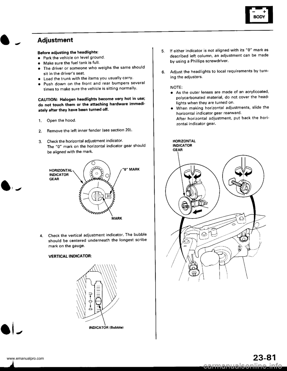
3. Checkthe horizontal adjustment indicator.
The "0" mark on the horizontal indicator gear should
be aligned with the mark.
"0" MARK
Check the vertical adjustment indicator. The bubble
should be centered underneath the longest scribe
mark on the gauge.
VERTICAL INDICATOR:
ol-
)
5.lf either indicator is not aligned with its "0" mark as
described left column, an adjustment can be made
by using a Phillips screwdriver.
Adjust the headlights to local requirements by turn-
ing the adjusters.
NOTE:
. As the outer lenses are made of an acrylicoated,
polycarbonated material, do not cover the head-
lights when they are turned on
. When making horizontal adiustments, slide the
horizontal indicator gear rearward.
After horizontal adjustment, put back the hori-
zontal indicator gear.
HORIZONTALINDICATORGEAR
23-A1
www.emanualpro.com
Page 1312 of 1395
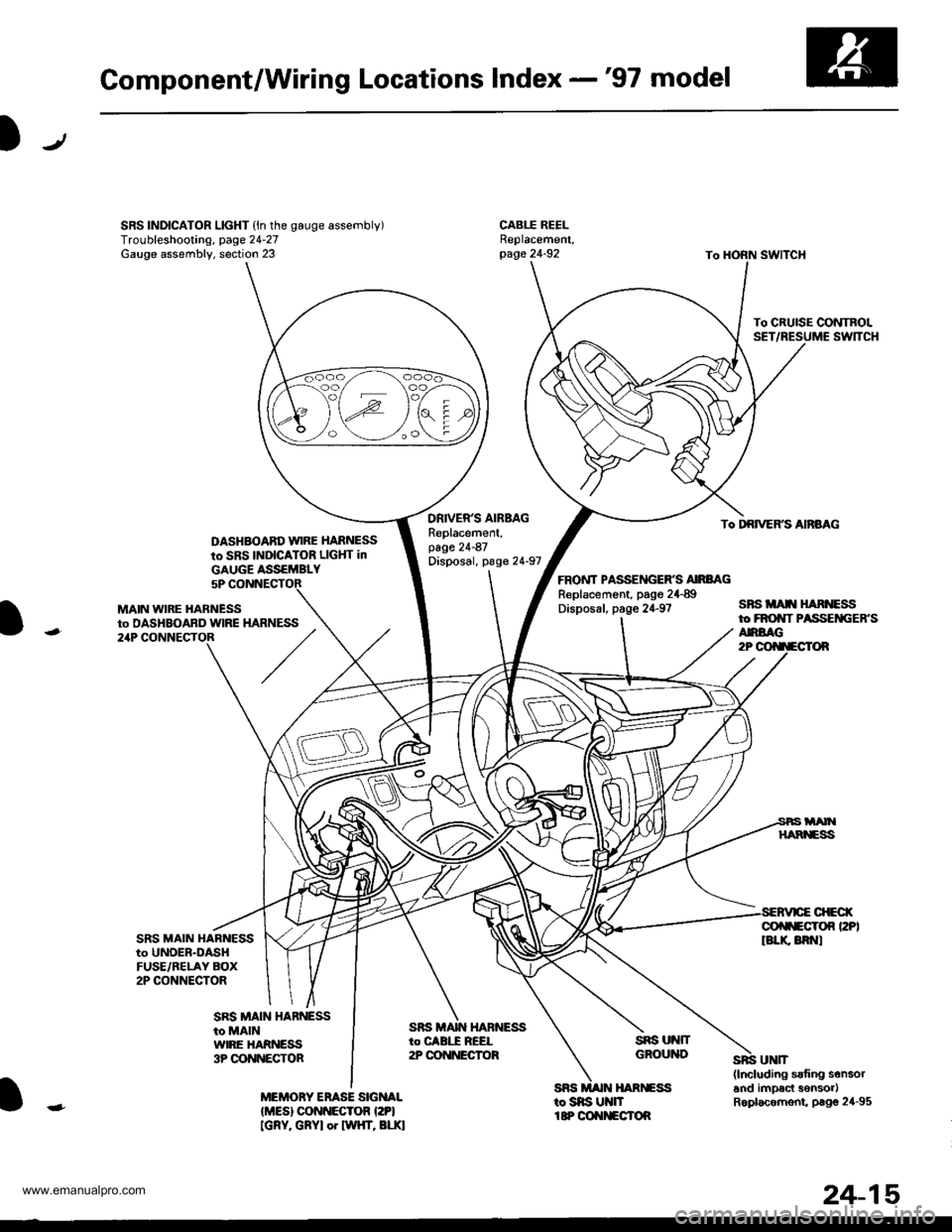
Component/Wiring Locations Index -'97 model
SRS INDICATOR LIGHT (ln the gauge assembly)Troubleshooting, page 24-27Gauge assembly, section 23
DASHBOABD w|RE HARNESS
to SBS INDICATOR LIGHT in
DRIVER'S AIBMGReplacement,page 21-87Disposal, page 24-97
To CRUISE CONTROLSET
To DRIVERS AnBAG
ANBAG2P
sBsitAr[ ] nNEssto FROI|T PASSEiIGEB.S
FRONT PASSEITGER'S AIRBAGReplacement, pago 24{9Disposal, page 24-97
sns ut{fTGROUND
SES MAIN HAR]GSStosns U nItP OOIIITECTOR
MAIN WIRE HABNESSto DASHBOABD wlRE21P
SRS MAIN HABNESSto UNOEB-DASHFUSE/BELAY BOX2P CONNECTOR
GOf$ECrOn PPIlBLr( 8R t
MEMORY ERASE SIGNALIMES) CONNECTOR I2PI[GRY. GRYI or twHT, BLr.l
GAUGE ASSEMBLY5P
HARNESS
SRS MAIN HARNESSto MAINWIRE HARNESS3P OONNECTOR
24-15
www.emanualpro.com
Page 1313 of 1395
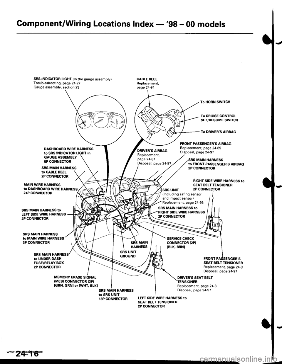
Gomponent/Wiring Locations Index -'98 - 00 models
SRS INDICAIOR LIcHT (ln the gauge assembty)Troubleshooting, page 24 27Gauge assembly. section 23
DASHBOARD WIRE HARNESSto SRS INDICATOR LIGHf inGAUGE ASSEMBLY5P CONNECTOR
FRONT PASSENGER'S AIRBAGReplacement, page 24-89Disposal, page 24 97
CABLE REELReplacement,page 24-91
To HORN SWITCH
To CRUISE CONTROLSET/RESUME SWTCH
To DRIVER'S AIRBAG
ro CABLE REEL2P CONNECTOR
MAIN VYIRE HARNESSto DASHBOARD WIRE HARNESS
SRS MAIN HARNESS
ORIVER'S AIRBAGReplacement,page 24-87Disposal, page 24-97
SRS UNIT
SRS MAIN HARNESSto FROI{T PASSENGER,S AIRBAG2P CONiIECTOR
RIGHT SIDE WIRE HARNESS toSEAI BELTTENSIONER2P CONNECTOR24P CONNECTOR
SRS MAIN
SRS MAIN HARNESS toLEFT SIDE WIRE HARNESS2P CONNECTOR
SRS MAIN HARNESSto MAIN WIRE HARNESS3P CONNECTOB
(lncluding safing sensorand impact sensor)Replacement, page 24-95
SRS MAIN HARNESS toRIGHT SIDE WIRE HARNESS2P CONNECTOR
SERVICE CHECKCONNECTOR I2PIIBLK BRNI
to UNDER-DASHFUSE/RELAY BOX2P CONNECTORSEAT BELT TENSIONERReplacement, page 24 3Disposal, page 24-97
ORIVER'S SEAT BELTMEMORY ERASE SIGNAL(MES) CONNECTOR I2PIIGRN, GRNI or IWHT, BLKIReplacement, page 24-3Disposal, page 24-97
LEFT SIDE WIRE HARNESS toSEAT BELTTENSIONER2P CONNECTOR
24-16
.4
www.emanualpro.com
Page 1315 of 1395
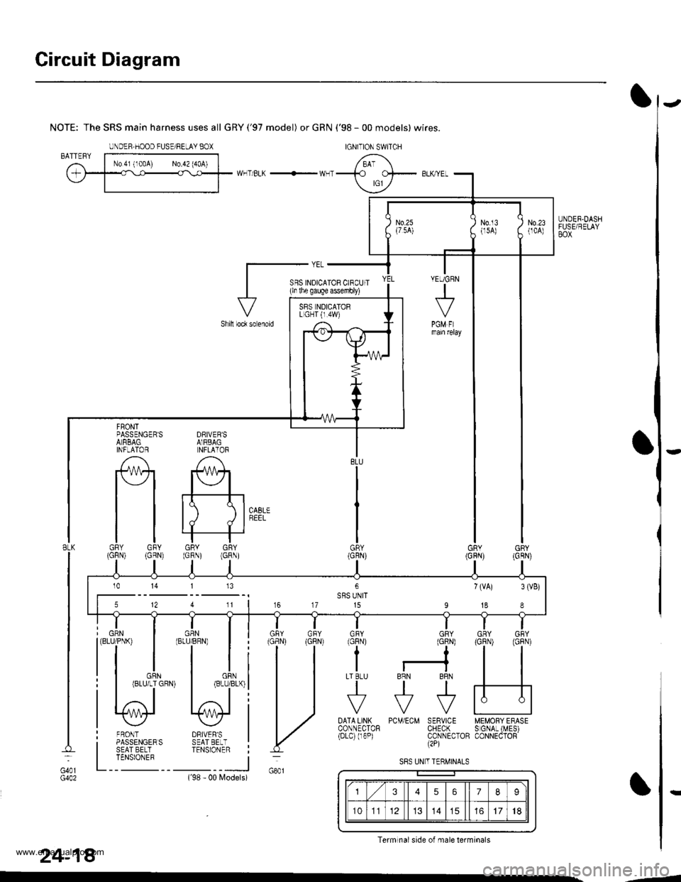
Circuit Diagram
UNDER.DASHFUSE/RELAYBOX
NOTE: The SRS main harness uses all GRY('97 model) or GRN ('98 - 00 models) wires.
WHT/BLK -'- WHT
DRIVEB'SAIRBAGNFLATOR
A
#+
tt tll./ d I
GRY GRY(GRN) (GRN)
FRONTPASSENGER'SALRBAGINFLAlOR
tlGRY GFY(GFN) (GRN)
DRIVER'SSEAT EELTTENSIONER
FRONTPASSENGERSSEAT BELTTENSIONEF
GRN(BLU/PNK)
BLK
G401
24-18
PCM/ECM SERVICE MEMORY ERASECHECK S GNAL (MES)CONNECTOB CONNECTOR(2P)
DATA LINXCONNECTOR(Drc) (r6P)
Models)('98 - 00
IGNITION SWITCHUNDEF,HOOD FUSE/RELAY BOX
YEUGRN
+
PGM FImam relay
SFS INDICATOR CIRCUIT(ln lhe gauge assembly)
Shill loc* so enoid
BLU
GR\
GNY GRY
H
GFY GRYlcFNt (GlN)
??
I r-?LT BLU BRN BRN
tttr?F?F
VVV
SRS NDICATORL GHT {r.4W)
5 12 4 11 | 16 17 15 I 18 I
10 14 113
U
S8S UN T TERMINALS
3567I
101114151718
Terminal side of male terminals
-4
www.emanualpro.com
Page 1330 of 1395
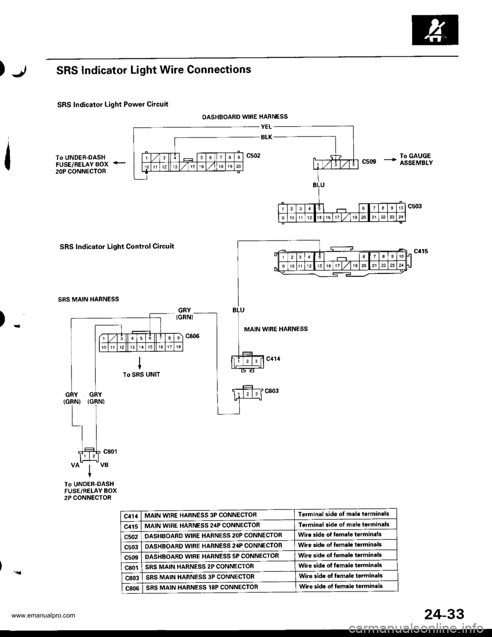
SRS Indicator Light Wire Connections
SRS Indicator Light Power Circuit
DASHBOARD WIRE HARNESS
YEL
BLK
To UNDER-DASHFUSE/RELAY BOX <_
20P CONNECTOR
To GAUGEcsog + assEMBLy
SRS Indicator Light Control Circuit
SRS MAIN HARNESS
)-MAIN WIRE HARNESS
VAIVBIt
To UNDER-DASHFUSE/BELAY BOX2P CONNECTOR
c414MAIN WIRE HARNESS 3P CONNECTORTerminal side of msle t€rminals
c415MAIN wlRE HARNESS 24P CONNECTORTerminal aide of male terminals
c502DASHBOARD WIRE HARNESS 2OP CONNECTORWire side of lemslo terminsls
c503OASHBOARD WIRE HARNESS 24P CONNECTORWire side of female t€rminal3
c509DASHBOABD WIRE HARNESS 5P CONNECTORWire sid€ ot lemale te.minals
c801SRS MAIN HARNESS 2P CONNECTORwire side ol f.male terminals
c803SRS MAIN HARNESS 3P CONNECTORWire side ol female terminals
c806SRS MAIN HARNESS T8P CONNECTORWire side of lomrle terminals
)
24-33
www.emanualpro.com
Page 1331 of 1395
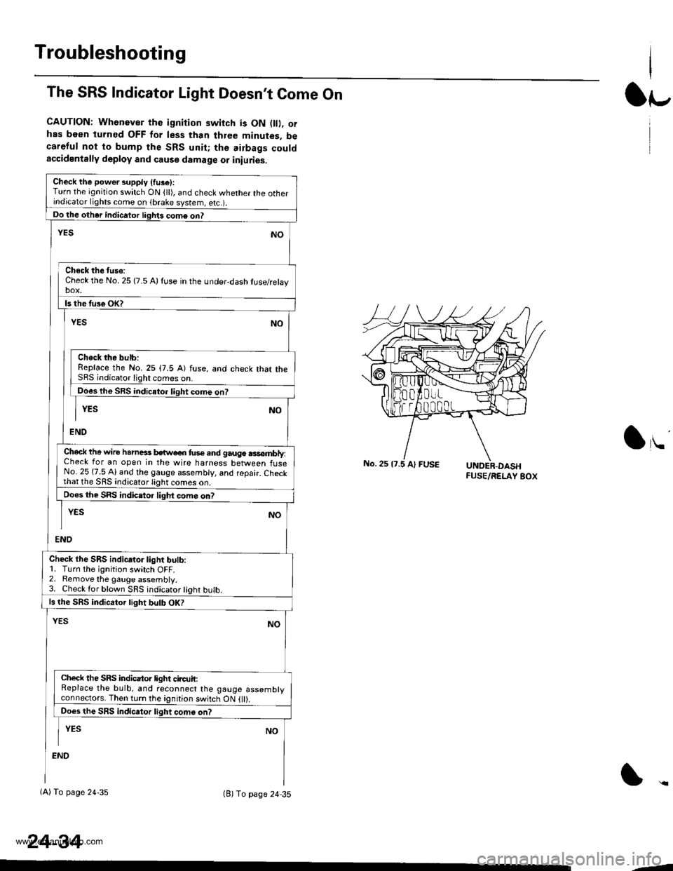
Troubleshooting
The SRS Indicator Light Doesn't Come On
CAUTION: Whenever the ignition switch is ON D, orhas been turned OFF for less than three minutes, becareful not to bump the SRS unit; the airbags couldaccidentally deploy and cause damage or iniuries.
Ch6ck the power supply (fuse):Turn the ignition switch ON {ll), and check whether the otherindicator lights come on (brake system, e(c.r.
Do the other indicator liglrts com6 on?
Check the No. 25 (7.5 A) fuse in the under-dash tuse/relayDOX.
ls the tus€ oK?
NO
Check the bulb:Replace the No.25 (7.5 A) fuse, and check that theSRS indicator light comes on.
Does the SRS indicator liqht come on?
YESNO
END
YES
Check the wire h.rnesi kwe€n fus€.nd gauge .3sembly:Check for an open in the wire harness between fuseNo. 25 (7.5 Al and the gauge assembly, and repair. Checkthat lhe SRS indicato.lighi
Does the SRS indic.tor liqht com6 on?
END
YESNO
Check the SRS indicator light bulb:1. Turn the ignition switch OFF.2. Remove the gauge assembly.3. Check lor blown SRS indicator tight bulb.
ls the SRS indicator tight bulb OK?
YESNO
Check the SRS indicator light circuit:Replace the bulb, and reconnect the gauge assemblyconneclors. Then turn the ignition switch ON {ll).
Does the SRS indicator light come on?
I YEs No
:ND
(A) To page 24-35(B) To page 24 35
24-34
lr-
lu
-J
www.emanualpro.com
Page 1332 of 1395
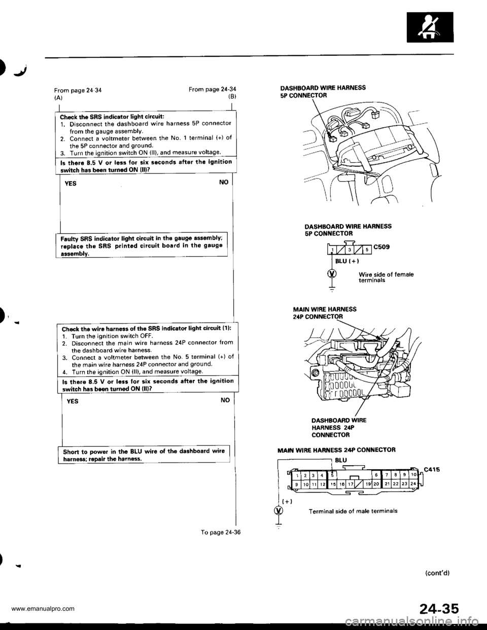
Chock th6 SRS indic.lor light circuit:1. Disconnect the dashboard wire harness 5P connector
from the gauge assembly.2. Connect a voltmeter between the No l terminal (+) o{
the 5P connector and grouncl.
3. Turn the ignition switch ON {ll), and measure voltage
ls thero 8.5 V or lats for 3ix second! aflsr the ignition
switch ha3 bo€n turnod ON (ll)7
YESNO
Fdulty SRS indicator light cilctlit in ths gauge sssomblY;
replaco tho SRS printod circuit board in the gauge
aasombly,
Chock th6 wire harn.$ of the SRS indicstor light circuh (11:
1. Turn the ignition switch OFF.2. Disconnect the main wire harness 24P connector from
the dashboard wire harness-3. Connect a voltmeter between the No 5 terminal (+) of
the ma;n wire harness 24P connecior and ground
4. Turn the ignition ON {ll), and measure voltage.
ls there 8,5 V or l€r3 tor six s€cond3 efter the ignilion
switch has bssn turnod ON llll?
YESNO
Short to powor in the BLU wire of tho dashbosrd wire
harne3s; Epait the harne3.s.
To page 24-36
Jt)
From page 24 34(A)From page 24-34(8)DASHBOARD WIRE HARNESS
5P CONNECTOR
DASHBOARD WIRE HARI{ESS5P CONI{ECTOR
c509
Wire side ol femaleterminals
)_
DASHBOARO WIREHARNESS 24PCONNECfOR
(cont'd)
MAIN WIRE HARNESS
MAIN WIRE HARI{ESS 2/tP COI{ ECTOR
Terminal side of male terminals
24-35
www.emanualpro.com
Page 1335 of 1395
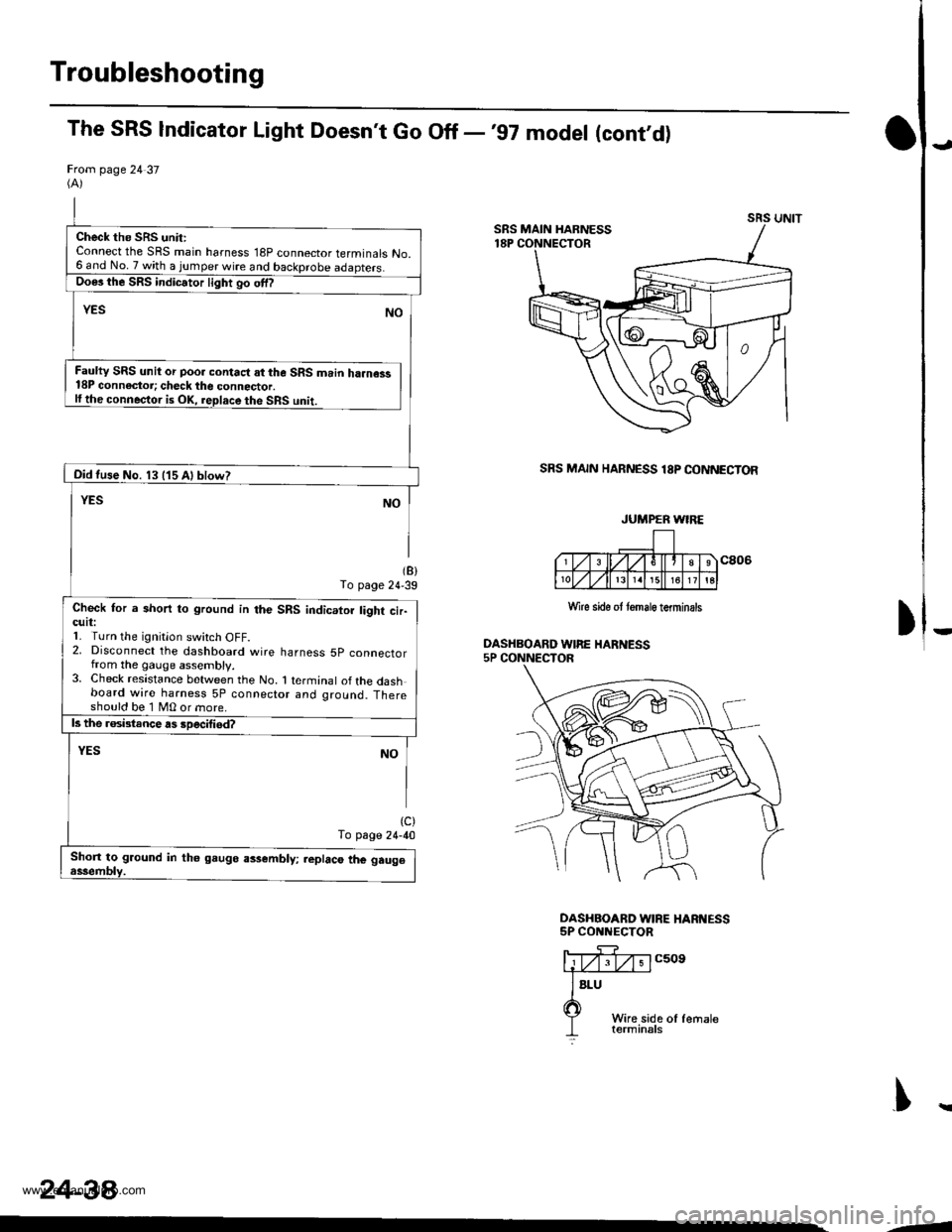
Troubleshooting
The SRS Indicator Light Doesn't Go Off - '97 model (cont,d)
From page 24 37(A)
SRS MAIN HARNESS 18P CONNECTOR
(B)To page 24'39
DASHBOARD WIRE HARNESS5P CONNECTOR
(c)To page 24-40
DASHBOAND WIRE HARI{ESS5P CONNECTOR
)
J
c509
Wire side ol femaleterminals
T
Check the SRS unit:Connect the SRS main harness 18P connector terminals No.6 and No.7 with a jumper wire and backprobe
Faulty SRS unit or poo. contact at the SRS main ha.ness18P connectoi; check the connector.lfthe conneqtor is OK, replace the SRS unit.
Oid tuse No. 13 (15 Al blow?
Check for a short to ground in the SRS indicator tight cir-cutl:1. Turn the ignitlon switch oFF.2, Disconnect the dashboard wire harness 5p connectorfrom the gauge assembly.3. Check resistance between the No. 1 terminal ofthe dashboard wire harness 5P connector and ground. Thereshould be 1 MO or more.
Shon to ground in th6 gaugo assembly; replaco the gau96
JUMPER WIRE
Wlre sido ot tomale terminsls
243a
--
www.emanualpro.com
Page 1336 of 1395
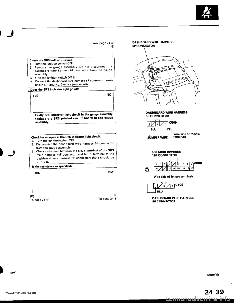
Check lhe SRS indicalor circuit:
1. Turn the ignition switch OFF
2. Remove the gauge assembly Do not disconnect the
dashboard wire harness 5P connector from the gauge
assemoly.3. Turn the ignition switch ON (ll).
4. Connect tie dashboard wire harness 5P connector termi-
nals No. I and No 5 with a iumper wire.
Does the SRS indicator light 90 otn
Faulty SRS indicator light circuit in the 9aug6 a$embly;
reolace the SRS printod circuit boa.d in th' gauge
Check tor rn open in the SRS indicator light circuit:
1. Turn the ignition switch OFF
2. Disconnect the dashboard wire harness 5P connector
from the gauge assemblY.
3. Check res]sta-nce between the No. 6 terminal ol the SRS
main harness 18P connector and No l terminal ol the
dashboard wire harness 5P connector; there should be
From page 24-38{B)
DASHBOARD WIRE HARNESS5P CONNECTOR
DASHBOARD WIRE HARNESS5P CONI{ECTOR
)
Y;yfivvcsosffi
I BLU IYELWir6.side of femaleJUMPER WIRE lormrna|s
SRS MAI HAN ESSt8P CO I{ECTOR
DASHBOARD WIRE HARNESS5P COI{NECTOR
{D)To page 24-41
1E)To page 24-41
)(cont'd)
Wire side oI fsmale terminals
24-39
www.emanualpro.com
Page 1340 of 1395
)
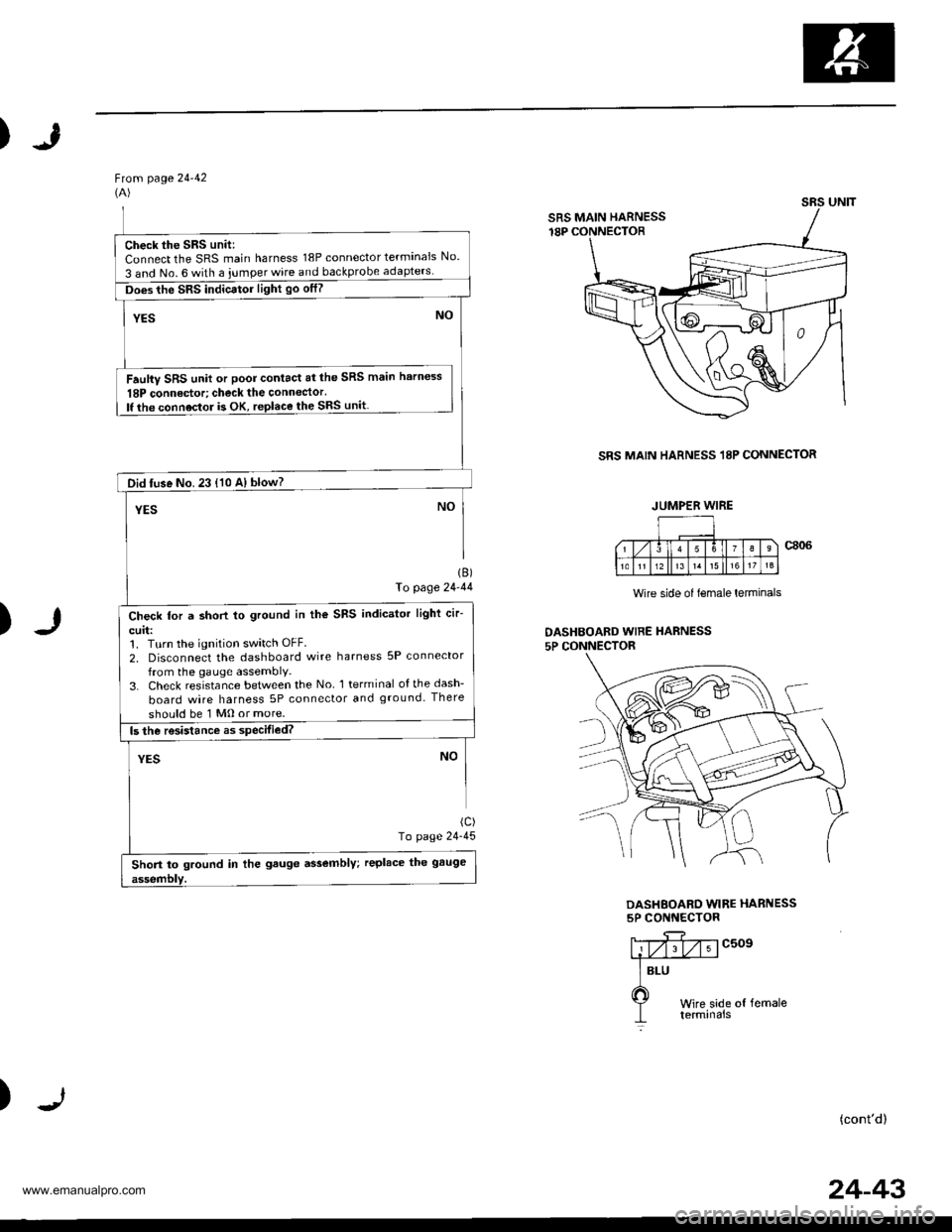
Ftom page 24-42(A)
SRS MAIN HARNESS 18P CONNECTOR
)
1B)fo page 24-44
(c)
To page 24-45
Wire side of lemale lerminals
DASHBOAED WIRE HARNESS5P CONNECTOR
DASHEOARD WIRE HARNESS5P CONNECTOR
c509
)(cont'd)
SRS UNIT
SRS MAIN HARNESS
Check the SRS unit:Connect the SRS main harness 18P connector terminals No.
3 and No. 6 with a iumper wire and backprobe
Does the SRS indicator light go otf?
Faulty SRS unit or poor contact at the SRS main harness
18P connedor; check the connector.lf the connoctor is OK, replace the SRS unit
Did tuse No. 23 {10 A} blow?
Check for a short to ground in the SRS indicator light cir-
curl:1. Turn the ignition switch OFF.
2, Disconnect the dashboard wire harness 5P connector
from the gauge assembly,3. Check resistance between the No l terminal ofthedash-
board wire harness 5P connector and ground. There
should be 1 Mo or more.
Short to ground in the gauge assembly; replace the gauge
JUMPER WIRE
24-43
www.emanualpro.com