Fluid HONDA CR-V 2000 RD1-RD3 / 1.G Workshop Manual
[x] Cancel search | Manufacturer: HONDA, Model Year: 2000, Model line: CR-V, Model: HONDA CR-V 2000 RD1-RD3 / 1.GPages: 1395, PDF Size: 35.62 MB
Page 1178 of 1395
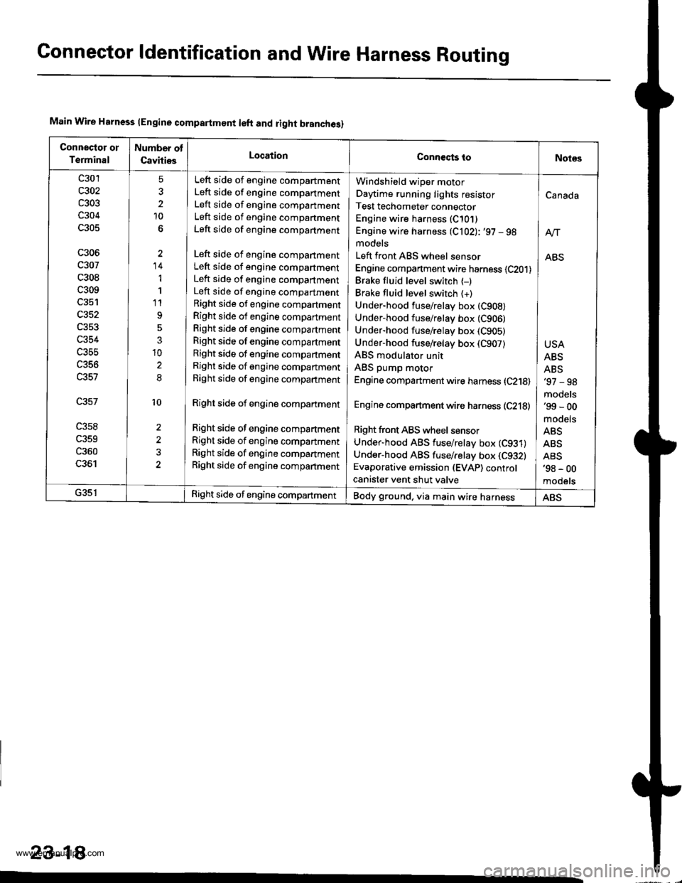
Gonnector ldentification and WireHarness Routing
Main Wire Harness lEngine compartmont left and right branches)
Connectot ol
Terminal
Number ot
CavitiesLocationConneqts toNot€s
c301
c303
c304
c305
c306
c307
c308
c309
c352
c354
c356
c357
c358
c359
c360
LJO I
5
2
10
'14
1
1
t1
3
10
8
10
2
Left side of engine compartment
Left side of engine compartment
Left side of engine compartment
Left side of engine companment
Left side of engine compartment
Left side of engine compartment
Left side of engine compartment
Left side of engine compartment
Left side of engine compartment
Right side of engine compartment
Right side of engine compartment
Right side of engine compartment
Right side of engine compartment
Right side of engine compartment
Right side of engine compartment
Right side of engine compartment
Right side of engine compartment
Right side of engine compartment
Right side of engine compartment
Right side of engine compartment
Right side of engine compartment
Windshield wiper motor
Daytime running lights resistor
Test techometer connector
Engine wire harness (C10])
Engine wire harness (C102): '97 - 98models
Left front ABS wheel sensor
Engine compartment wire harness (C201)
Brake fluid level switch {-)Brake fluid level switch (+)
Under-hood fuse/relay box (C908)
Under-hood fuse/relay box (C906)
Under-hood fuse/relay box (C905)
Under-hood fuse/relay box (C907)
ABS modulator unit
ABS pump motor
Engine compartment wire harness (C218)
Engine compartment wire harness (C218)
Right front ABS wheel sensor
Under-hood ABS fuse/retay box (C931)
Under-hood ABS fuse/relay box (C9321
Evaporative emission (EVAP) controcanister vent shut valve
Canada
ABS
USA
ABS
ABS'97 - 98
models'99 - 00
mooets
ABS
ABS
ABS'98 - 00
mooets
G35lRight side of engine compartmentBody ground, via main wire harnessABS
23-18
www.emanualpro.com
Page 1207 of 1395

BLKG401
GroundWir€ ColorComponent or Circuits Grounded
ABS indicator circuit
ABS control unit
Ashtray light
A/T gear position indicator dimming circuit
Brake fluid level switch
Clock ('98 - 00 models)
Clutch inrerlock switch (M/T)
Clutch switch (Mff)
Cruise main switch
Cruise indicator circuit
Cruise control unit
Dash lights brightness controller
Data iink connector
Daytime running rights control unit (Canada)
Front accessary socket
Gauge and indicators
Heater control panel
lgnition key light control unit ('97 model)
lgnition key switch
Integrated control unit
Interlock control unit (Ay'T)
Parking pin switch {A,/T)
Power window relay
Rear accessary socket relay
Bear window defogger relay
Rear window wiper control unit ('97 model)
Service check connector
Spotlights
SRS indicator circuit
Turn signal/hazard relay
Windshield wiper motor
Windshield wiper/washer switch- plus everything grounded through G402
ABS control unit
Blower motor relay
Blower motor high relay
ELD unit (USA)
Power transistor- plus everything grounded through G401
BLKG402
{cont'd)
23-47
www.emanualpro.com
Page 1210 of 1395
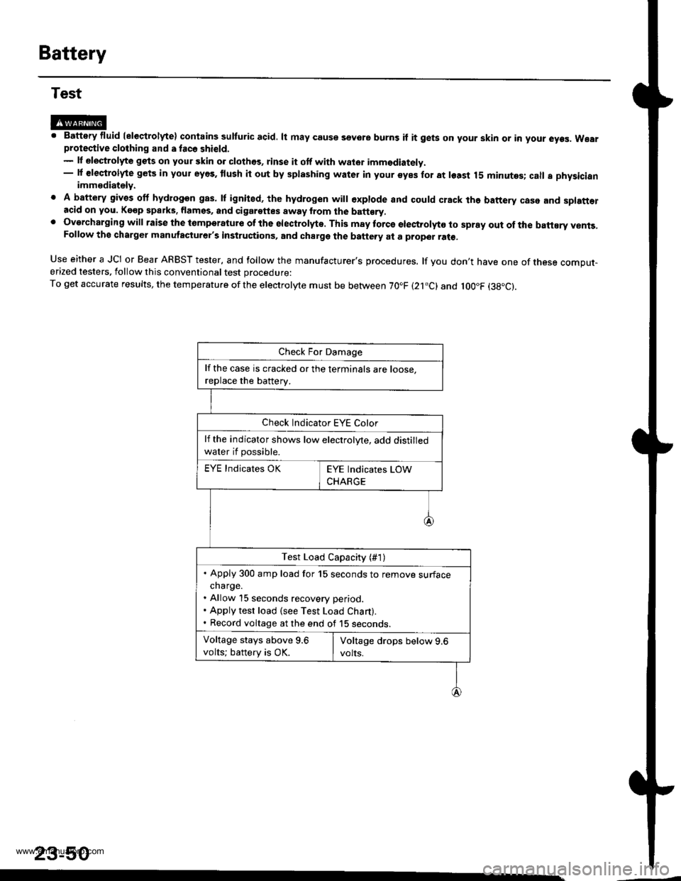
Battery
Test
@M. Battery fluid (eleqtrolyte) contains sulturic acid. lt may couse sevore burns if it gets on your skin or in your eyes. Wearprotective clothing and a fac6 shield.- lf elestrolyte gets on your skin o. clothos, rinse it otf with wator imm€diately.- lf €leqtrolyte gets in your eyes. tlush it out by splashing water in your syes for at least 15 minutes; call a physicianimmediately.
. A battery gives off hydrogon gas. lf ignited, the hydrogen will €xplode and could crack the battery case and splatt€racid on you. Kgop sparks. flamss, and cigarettes away from the batt€ry,. Overcharging will raise the tomperatute of the electrolyte. This may torcs electrolyto to spray out of the battEry vents,Follow the charger manutacturer's instructions, and charge the battery at a proper ral€,
Use either a JCI or Bear ARBST tester, and follow the manufacturer's procedures. lf you don't have one of tnese comput-erized testers, follow this conventional test procedure:
To get accurate results, the temperature ofthe electrolyte must be between 70.F (21.c) and loo"F (38"c).
23-50
lf the case is cracked or the terminals are roose.
replace the batterv.
Check Indicator EYE Color
lf the indicator shows low electrolyte, add distilled
water if possible.
EYE Indicates OK
Test Load Capacity (#1)
. Apply 300 amp load for 15 seconds to remove surfacecharge.. Allow 15 seconds recovery period.. Apply test load (see Test Load Chart).. Record voltage at the end of 15 seconos.
Voltage stays above 9.6
volts; battery is OK.
www.emanualpro.com
Page 1215 of 1395
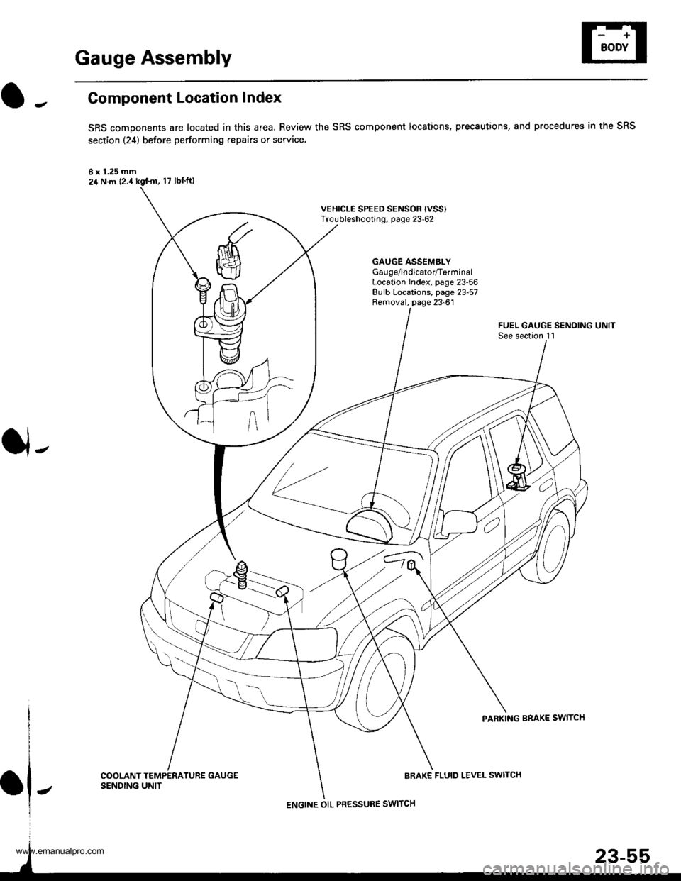
Gauge Assembly
Component Location Index
SRS components are located in this area. Review the SRS component locations, precautions, and procedures in the SRS
section {24} before performing repairs or service.
I x 1.25 mm24 N.m {2.4
VEHICLE SPEED SENSOF {VSS'Troubleshooting, page 23-62
GAUGE ASSEMBLYGau ge/lndicator/TerminalLocation Index, page 23-56Bulb Locations, page 23-57Removal, page 23-61
J-
FUEL GAUGE SENDING UNITSee section 1 l
PARKING BRAKE SWITCH
COOLANT TEMPERATURE GAUGESENDING UNITBRAKE FLUID LEVEL SWITCH
ENGINE OIL PRESSURE SWITCH
www.emanualpro.com
Page 1227 of 1395
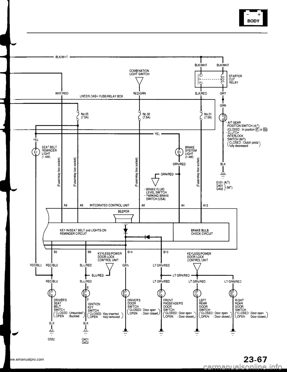
GRY
IGRN
I
rql)
Y4-orotI POSTT1ON SWTTCH (A/T)I (cLosED In posrlion Eor NII . CLUTCNI INTERLOCKI swrTcH (M,T)I /CLOSED :Clulch Dedal\
| \lullydeprsssed I
II8LK
{
Gl01 (A,T)
f;iillrvrr
-"'-},,,,,"
Y l1eff E
v**JT"
g
' BFAKE FLUIDLEVEL SWITCH'PARKING BRAKEswrTcH (usA)
A8A6 INTEGRATED CONTROL UNIT
KEY]N/SEAT BELT and LIGHTS.ONREMINDER CLRCUIT
COMBlNATIONLIGHT SWIlCH
\-7
IREO/GFN
KEYLESS/POWERDOOB LOCKCONTROL UNlT
V
GFN/nED+-]
LTGRN/R€D LT GRN/RED
tl
d[' 4P'\\s.i
EF's l*'n IFF^I'
13fft" l39P*:Door oper ) | fCLOSED. Doo'open ) | fCLO#D. Door ooe. ). Door dos€d,
I
\oPE . 000' closed,
|
\oPE Door ciosed,
ll-- --
,,,[:
ltrh::ffIxl,,'.l'"
l*,*,J IBLU/ BED I
AA
Y Y*,u,.,
I cvro | Bft_oi|l
sl:$P)l lHfi.#' Hrtrff"% ) l
(3!?i".
TI:l
G40tG402
6
DRIVER'SSEATBELTswrTcHrcLosED(OPEN
YEL
RED/BLU
SEAT EELTREM NDERLIGHT(1.4W)
\-
i
I
:
*,
/BLU RED/BLU
q
FEO/BLU
I
dF)
Y*lsE
13fr
l(3BtK
4
www.emanualpro.com
Page 1230 of 1395
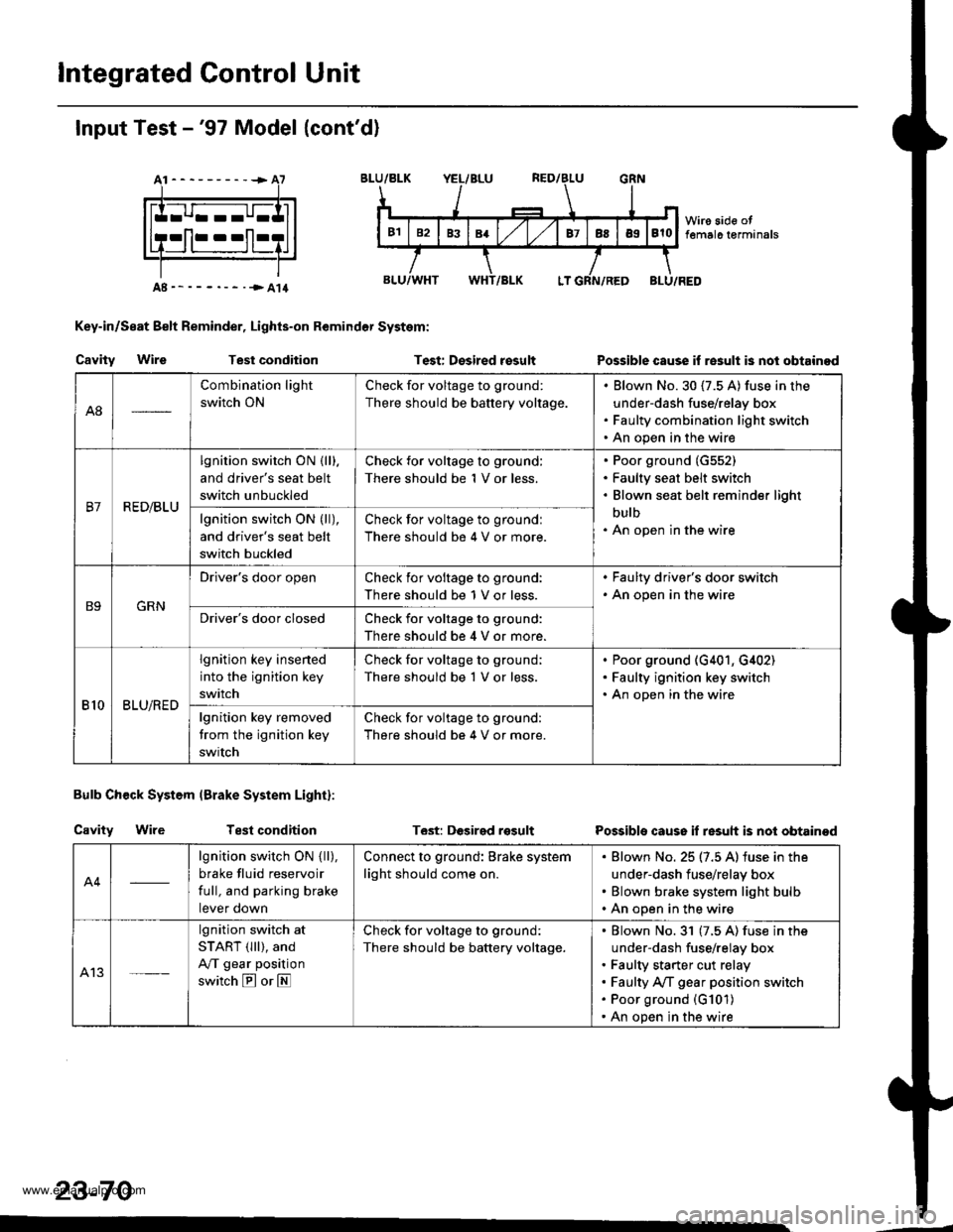
lntegrated Control Unit
Input Test -'97 Model (cont'd)
At----------+A7
Key-in/Seat Belt Reminder, Lights-on Remindor System:
Cavity WireTest conditionTest: Desired rosultPossible cause if re3ult is nol obtainod
Bulb Check System (Brake System Light):
Cavity WireTest conditionT6st: DGsirgd rosultPossible cause if resuh is not obtainod
23-70
A8
Combination light
switch ON
Check for voltage to ground:
There should be battery voltage.
Blown No.30 (7.5 A) fuse in the
under-dash fuse/relay box
Faulty combination light switch
An open in the wire
B7R ED/BLU
lgnition switch ON {lll.
and driver's seat belt
switch unbuckled
Check for voltage to ground:
There should be 1 V or less.
Poor ground (G552)
Faulty seat belt switch
Blown seat belt reminder light
bulb
An open in the wirelgnition switch ON (ll),
and driver's seat belt
switch buckled
Check for voltage to groundl
There should be 4 V or more.
B9GRN
Driver's door openCheck ior voltage to ground:
There should be 1 V or less.
. Faulty driver's door switch. An open in the wire
Driver's door closedCheck for voltage to ground:
There should be 4 V or more.
810BLU/RED
lgnition key insened
into the ignition key
switch
Check for voltage to ground;
There should be 1 V or less.
Poor ground (G401, G,[02)
Faulty ignition key switch
An open in the wire
lgnition key removed
trom the ignition key
swrtch
Check for voltage to ground:
There should be 4 V or more.
A4
lgnition switch ON { ll),
brake fluid reservoir
full, and parking brake
tever oown
Connect to ground: Brake system
light should come on.
Blown No. 25 (7.5 A) iuse in the
under-dash fuse/relay box
Blown brake system light bulb
An open in the wire
A13
lgnition switch at
START (lll), and
A/T gear position
switch E or E
Check for voltage to ground:
There should be battery voltage.
Blown No.31 (7.5 A) fuse in the
under-dash fuse/relay box
Faulty starter cut relay
Faulty A/f gear position switch
Poor ground (G101)
An open in the wire
www.emanualpro.com
Page 1234 of 1395
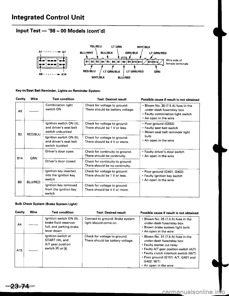
Integrated Control Unit
A1 --------> A7
Input Test -'98 - 00 Models (cont'dl
YEL/BLULT GRNWHT/BLK
GRN/BLKLT GRN/REO
Wire side offemale terminals
A8------->A14WHT/BLK
Key-in/Se8t Beft Reminder, Lights-on Remindol System:
BLU/RED
Cavity WireTest conditionTest: Desired resultPossible caus€ it result is not obtained
Bulb Check System lBrake System Lightl:
Cavity WireTest conditionTest: Desired resultPossible caus€ if result is not obtained
A4
lgnition switch ON (ll),
brake fluid reservoir
full, and parking brake
lever down
Connect to ground: Brake system
light should come on.
Blown No. 25 (7.5 A) fuse in the
under-dash fuse/relay box
Blown brake system light bulb
An open in the wire
A13
lgnition switch at
START ( lll), and
A,/T gear position
switch E or E
Check for voltage to ground:
There should be battery voltage.
Blown No. 31 {7.5 A) fuse in the
under-dash fuse/relay box
Faulty sta rter cut relay
Faulty A,/T gear position switch (A,/T)
Faulty clutch interlock switch (M/T)
Poor ground {G101: AfI. G401 and
G402: M/T)
An open in the wire
23-74
A8
Combination light
switch ON
Check for voltage to ground:
There should be battery voltage.
Blown No. 30 (7.5 A) fuse in the
under-dash fuse/relay box
Faulty combination light switch
An open in the wire
RED/BLU
lgnition switch ON ( ll),
and driver's seat belt
switch unbuckled
Check for voltage to ground:
There should be 1 V or less.
Poor ground {G552)
Faulty seat belt switch
Blown seat belt reminder light
bu lb
An open in the wirelgnition switch ON (ll),
and driver's seat belt
switch buckled
Check for voltage to ground:
There should be 4 V or more.
814GRN
Driver's door openCheck for continuity to ground:
There should be continuity,
. Faulty driver's door switch. An open in the wire
Driver's door closedCheck for continuity to ground:
There should be no continuity.
B8BLU/RED
lgnition key inserted
into the ignition key
swrtch
Check for voltage to ground:
There should be 'l V or less.
Poor ground (G401, G402)
Faulty ignition key switch
An open in the wire
lgnition key removed
from the ignition key
switch
Check for voltage to ground:
There should be 4 V or more.
www.emanualpro.com
Page 1239 of 1395
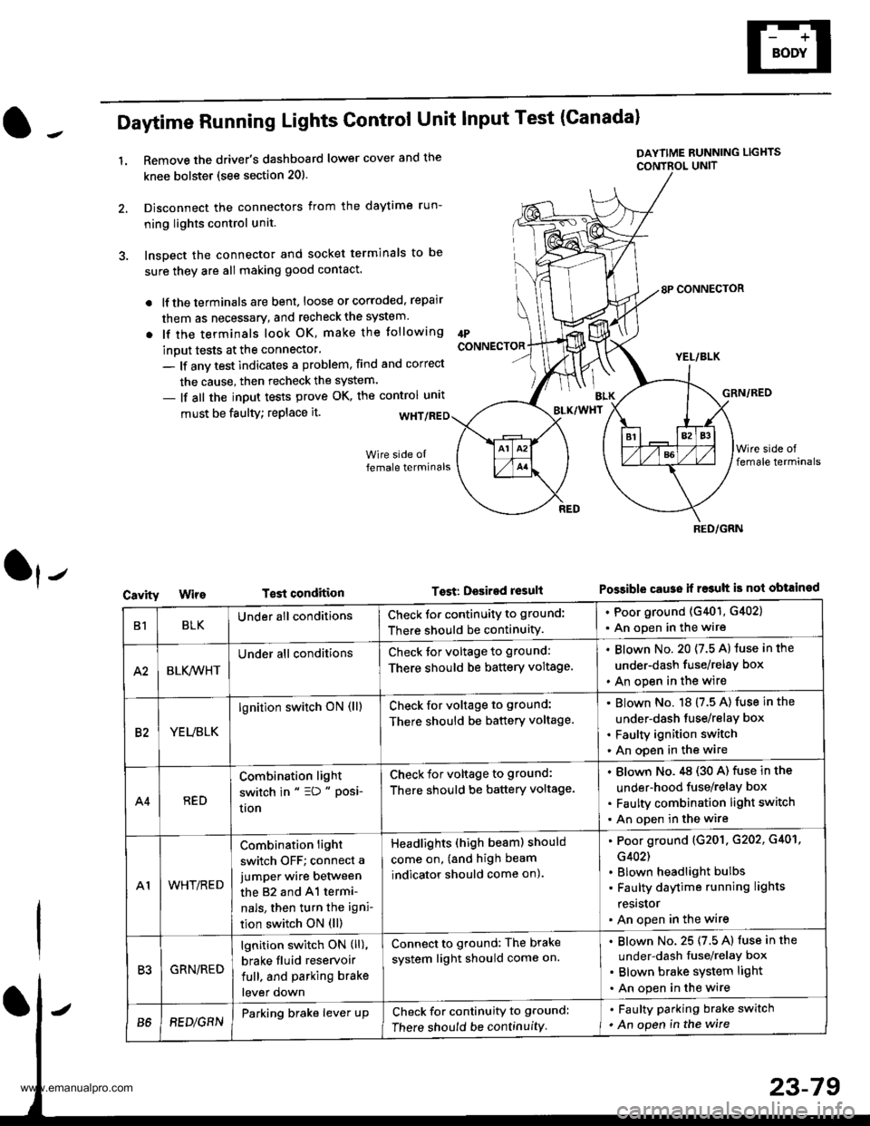
Daytime Running Lights Control Unit Input Test (Canadal
1.Remove the driver's dashboard lower cover and the
knee bolstet (see section 20).
Disconnect the connectors from the daytime run-
ning lights control unit.
Inspect the connector and socket terminals to be
sure they are all making good contact.
lf the terminals are bent, loose or corroded, repair
them as necessary, and recheck the system.
lf the terminals look OK, make the tollowing
inout tests at the connector'
- lf anv test indicates a problem, find and correct
the cause, then recheck the system.
- lf all the input tests prove OK, the control unrt
IPCONNECTOR
must be faulty; replace it.
T€st condition
DAYTIME RUNNING LIGHTS
CONTBOL UNIT
Tost: Desired result
8P CONNECTOR
YEL/BLK
GRN/RED
Possible cause ii r$uh is not obtained
BLK/WHT
Cavity
RED/GRN
B1BLKUnder all conditionsCheck for continuity to ground:
There should be continuity.
. Poor ground (G401, G402)
. An open in the wire
A2BLK,4iVHT
Under all conditionsCheck tor voltage to ground:
There should be battery voltage.
Blown No. 20 (7.5 A) luse in the
under-dash fuse/relay box
An open in the wire
82YEUBLK
lgnition switch oN (ll)Check for voltage to ground:
There should be battery voltage.
Blown No. 18 (7.5 A) fuse in the
under-dash tuse/relay box
Faulty ignition switch
An open in the wire
A4RED
Combination light
switch in " =D " Posi-
uon
Check for voltage to ground:
There should be battery voltage.
Blown No.,tg (30 A) fuse in the
under-hood fuse/relay box
Faulty combination light switch
An open in the wire
A1WHT/RED
Combination light
switch OFF; connect a
jumper wire between
the 82 and 41 termi-
nals, then turn the igni-
tion switch ON (ll)
Headlights (high beam) should
come on, (and high beam
indicator should come on).
Poor ground (G201. G202, G401,
G402)
Blown headlight bulbs
Faulty daytime running lights
resrslor
An open in the wire
R'IGRN/RED
lgnition switch ON (ll),
brake fluid reservoir
full. and parking brake
lever down
Connect to ground: The brake
system light should come on.
Blown No. 25 (7.5 A) fuse in the
under-dash fuse/relaY box
Blown brake system light
An open in the wire
B68EDlGRNParking brake lever upCheck for continuity to ground:
There should be continuity
. Faulty parking brake switch
. An open in the wire
www.emanualpro.com
Page 1280 of 1395
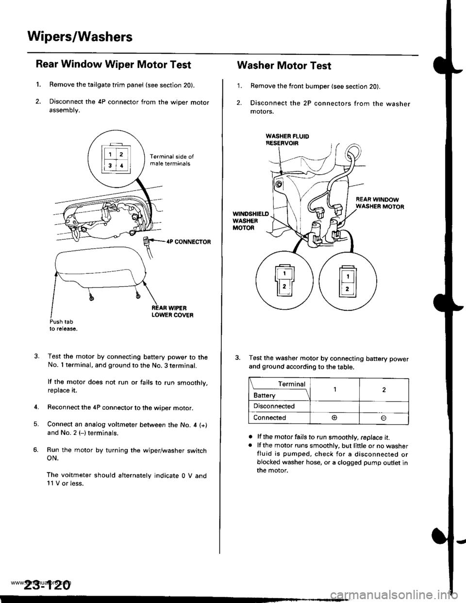
Wipers/Washers
1.
Rear Window Wiper Motor Test
Remove the tailgate trim panel (see section 20),
Disconnect the 4P connector from the wiper motor
assembly.
4P CONNECTOR
WIPEBLOWER COVEnPush tabto release,
Test the motor by connecting battery power to theNo. I terminal, and ground to the No. 3 terminal.
lf the motor does not run or fails to run smoothly,replace it.
Reconnect the 4P connector to the wiper motor.
Connect an analog voltmeter between the No. 4 (+)
and No. 2 (-) terminals.
Run the motor by turning the wiper/washer switchoN.
The voltmeter should alternately indicate 0 V and11 V or less.
4.
5.
23-120
1.
Washer Motor Test
Remove the front bumper (see section 20).
Disconnect the 2P connectors from the washermolors,
REAR WINDOWWASHER MOTOR
Test the washer motor by connecting battery power
and ground according to the table.
lf the motor fails to run smoothly, replace it.lf the motor runs smoothly, but little or no washerfluid is pumped, check for a disconnected orblocked washer hose, or a clogged pump outlet inthe motor.
a
a
L_Iq'.r91
Battery
,l
Disconnected
Connected@
www.emanualpro.com