HONDA CR-V 2000 RD1-RD3 / 1.G Workshop Manual
Manufacturer: HONDA, Model Year: 2000, Model line: CR-V, Model: HONDA CR-V 2000 RD1-RD3 / 1.GPages: 1395, PDF Size: 35.62 MB
Page 1261 of 1395
E
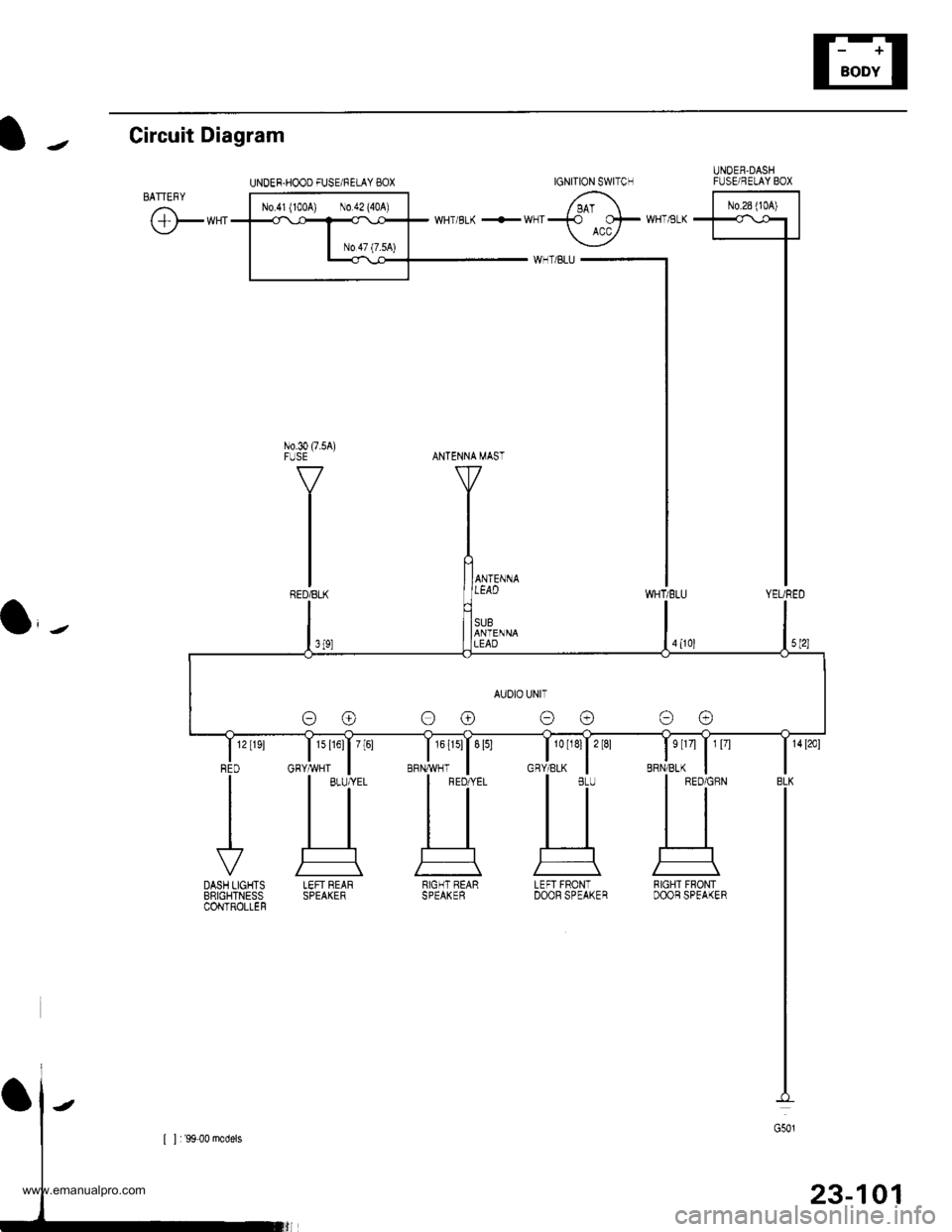
t J Circuit Diagram
UNDER.HOOO FUSE/FELAY BOXUNOEB,DASHFIJSE/RELAY BOX
l-^*"-l
T'5 1-T
I
I
I
I
I
IYEURED
No.30 (7.5A)FUSE
WHT,tsLK
BRN/BLK
s tr4 | 1 l7l
a,-,
1s l16l| 7[61
GHY,ryVHT
IGNITION SWITCH
AUOIO UNIT
oo oo
LEFT REARSPEAKERRIGHT BEARSPEAKERLEFI FRONTDOOF SPEAKERRIGHT FBONTDOOB SPEAKER
23-101
www.emanualpro.com
Page 1262 of 1395
Stereo Sound System
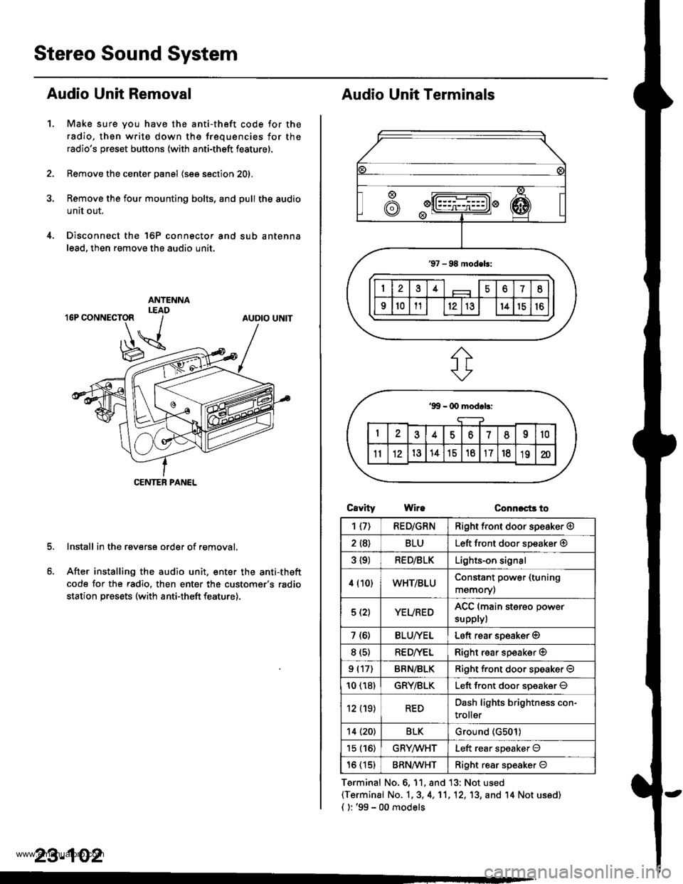
Audio Unit Removal
Make sure you have the anti-theft code for the
radio, then write down the frequencies for the
radio's preset buttons (with anti-theft feature).
Remove the center panel (see section 201,
Remove the four mounting bolts, and pull the audio
unit out.
Disconnect the 'l6P connector and sub antenna
lead, then remove the audio unit.
Install in the reverse order of removal.
After installing the audio unit, enter the anti-theft
code for the radio. then enter the customer's radio
station presets (with anti-theft feature).
1.
AUDIO UNIT
CENTEB PANEL
23-102
Audio Unit Terminals
CavrtyWireConnoct3 to
Terminal No.6, 11, and 13: Not used(Terminal No. 1,3, 4,'11,12, 13, and '14 Not us6d)
{ ): '99 - 00 models
1{7)RED/GRNRight front door speaker @
2 {8}BLULeft front door speaker @
3 {9)RED/BLKLights-on signal
4 (10)WHT/BLUConstant power (tuning
memory)
5 (2)YEUREDACC (main sterso power
supplyl
7 (6)BLU/YELLeft rear soeaker @
8 (s)RE D/VELRight rear speaker @
9 (17)BRN/BLKRiqht f.ont door speaker O
10 (18)GRY/BLKLeft front door soeaker O
12 (19)REDDash lights brightness con-
troller
14 (20)BLKGround (G501)
15 (16)GRYMHTLeft rear speaker O
16 (15)BRN^ll/HTRight resr speaker O
www.emanualpro.com
Page 1263 of 1395
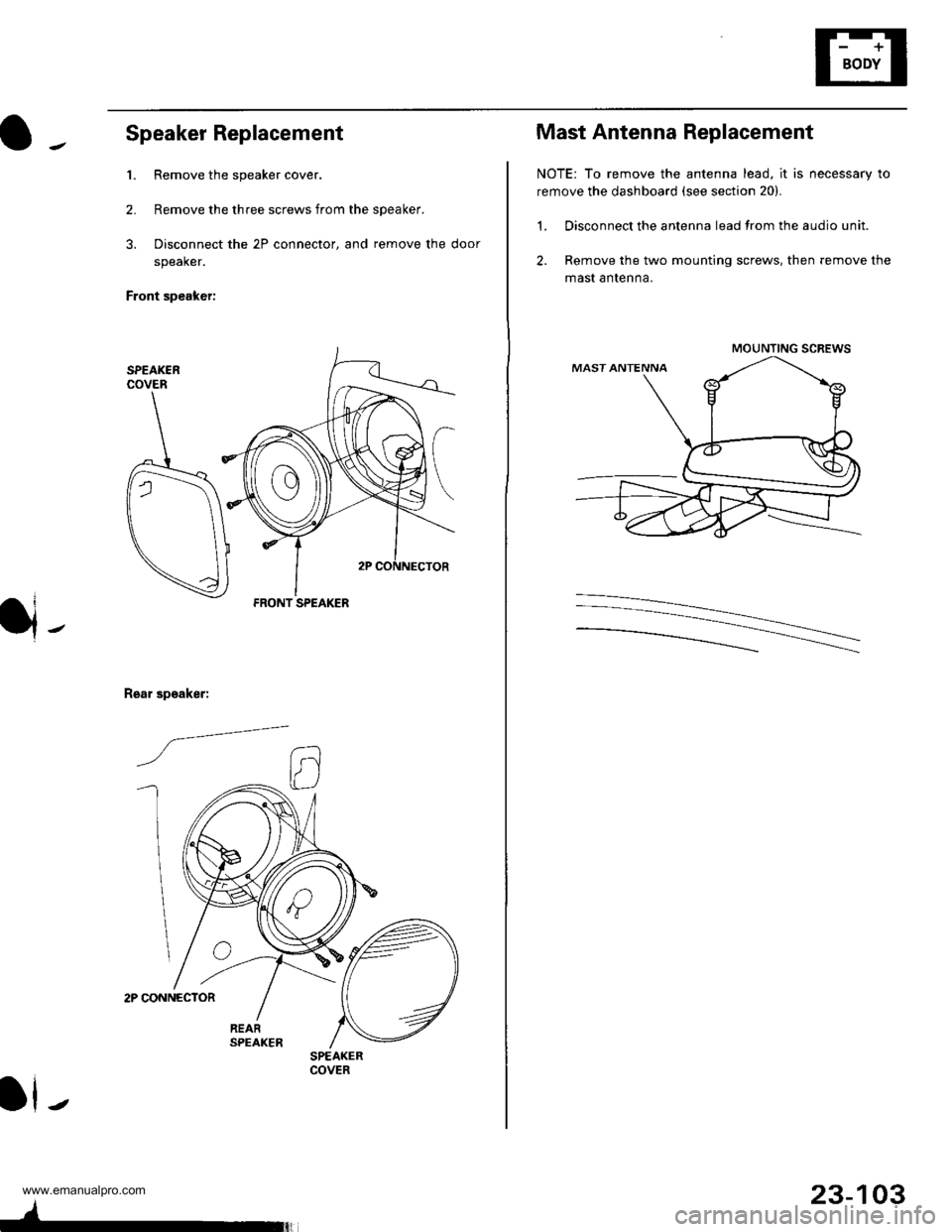
Speaker Replacement
1. Remove the speaker cover.
2. Remove the three screws from the speaker.
3. Disconnect the 2P connector, and remove the door
speaker.
Front speaker:
2P CONNECTOR
Rear speaker:
/a--=-
ll-
FRONT SPEAKER
SPEAKERCOVER
4-
23-103
Mast Antenna Replacement
NOTE: To remove the antenna lead, it is necessary to
remove the dashboard (see section 20).
1. Disconnect the antenna lead from the audio unit.
2. Remove the two mounting screws, then remove the
mast antenna.
MOUNTING SCREWS
www.emanualpro.com
Page 1264 of 1395
Horns
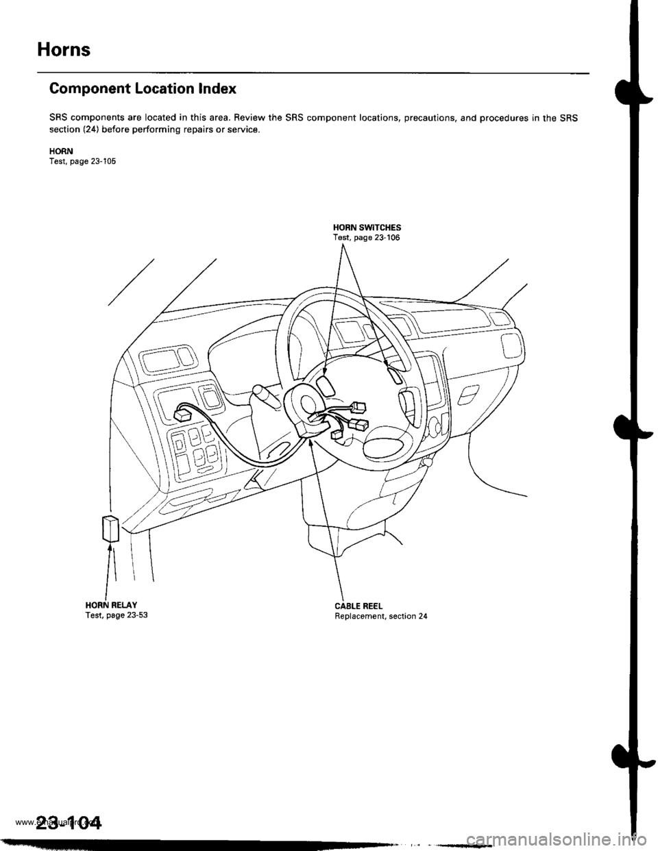
Component Location Index
SRS components are located in this area, Review the SRS component locations, precautions, and procedures in the SRS
section (24) before performing repairs or service.
HORNTest, page 23-105
HORN SW|TCHESTest, page 23-106
m
/\HORN RELAYTest. page 23-53Replacement, section 24CAELE REEL
23-104
www.emanualpro.com
Page 1265 of 1395
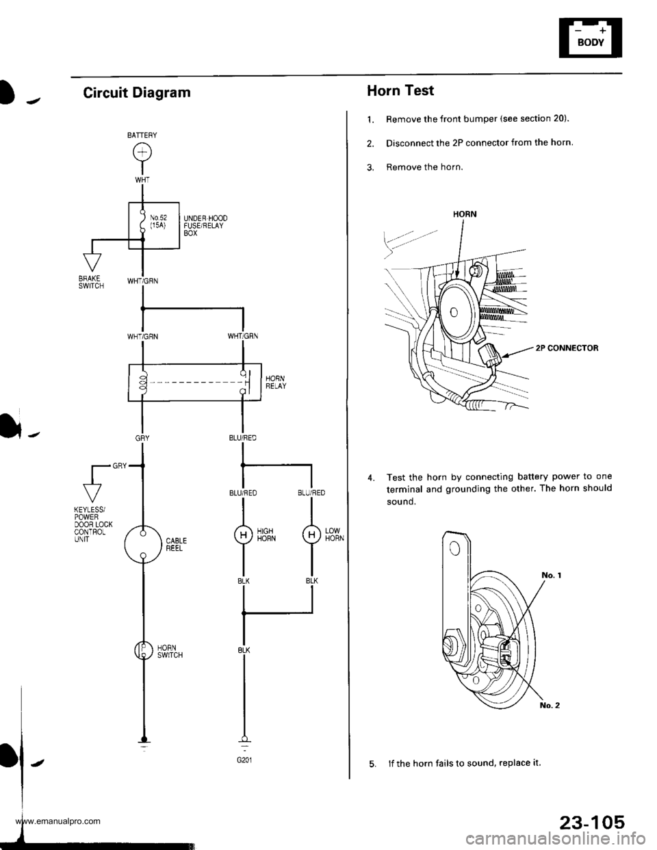
Horn Test
1. Remove the front bumper (see section 20).
2. Disconnect the 2P connector from the horn
3, Remove the horn.
2P CONNECTOR
Test the horn by connecting battery power to one
terminal and grounding the other. The horn should
sound.
4.
HORN
23-105
5. lf the horn fails to sound, replace it
Circuit Diagram
}-BLU/FED
I
BLUi FEO BLU/RED
II
g)iirrN I
tlBLK BLK
ll
IBLK
I
I
I
G201
fl"'
LOWHORN
KEYLESSiPOWEFDOOR LOCKCONTROLUNIT
www.emanualpro.com
Page 1266 of 1395
Horns
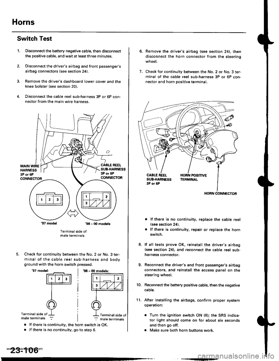
Switch Test
Disconnect the battery negative cable, then disconnect
the positive cable, and wait at ieastthree minutes.
Disconnect the driver's airbag and front passenger's
airbag connectors (see section 24).
Remove the drive.'s dashboard lower cover and the
knee bolster (see section 20).
Disconnect the cable reel sub-harness 3P or 6P con-
nector from the main wire harness.
1.
MAIN WIREHARNESS3P o. 6P
CABI.I REELSUB.HARNESS3P or 6PCONNECTORCONNECTOR
37 modol ,98 - 0O modots
Terminal side ofmale terminals
Check for continuity between the No. 2 or No. 3 ter-
minal of the cable reel sub-harness and bodyground with the horn switch pressed.
'97 model:'98 - (X) modols:
Terminalside of
. lf there is continuity. the horn switch is OK.. lf there is no continuity, go to step 6.
23-106
Terminal side of
6.Remove the driver's airbag (see section 241, then
disconnect the horn connector from the steerinq
wneet.
Check for continuity between the No. 2 or No. 3 ter-
minal of the cable reel sub-harness 3P or 6P con-
nector and horn Dositive terminal.
lf there is no continuity, replace the cable reel(see section 24).
lf there is continuity. repair or replace the horn
switch.
lf sll tests prove OK, reinstall the driver's airbag(see section 24), and reconnect the cable reel sub-
harness connector.
Reconnect the driver's and front passenger's airbag
connectors, and reinstall the access panel on the
steering wheel.
Reconnect the battery positive cable, then the negative
cable.
After installing the airbags, confirm proper system
operatron:
. Turn the ignition switch ON (ll); the SRS indica-
tor light should come on for about six seconds
and then go off.
. Make sure both horn buttons work.
7.
11.
8.
9.
10.
HORN CONNECTOR
www.emanualpro.com
Page 1267 of 1395
![HONDA CR-V 2000 RD1-RD3 / 1.G Workshop Manual
Power Mirrors
Circuit Diagram
IGNITION SWITCH
lBAI \-€l ^rc2l.Y
YEL
I
-t----t
I lu.x I
IBLKIryEL
@"*
POWEN MIRRON SWTCH
UNDER,DASHFUSE/RELAYB0x
GRN vHT +l
35
BLK
-:
G551
l,-
[ ] : 9&00 rnodels
U HONDA CR-V 2000 RD1-RD3 / 1.G Workshop Manual
Power Mirrors
Circuit Diagram
IGNITION SWITCH
lBAI \-€l ^rc2l.Y
YEL
I
-t----t
I lu.x I
IBLKIryEL
@"*
POWEN MIRRON SWTCH
UNDER,DASHFUSE/RELAYB0x
GRN vHT +l
35
BLK
-:
G551
l,-
[ ] : 9&00 rnodels
U](/img/13/5778/w960_5778-1266.png)
Power Mirrors
Circuit Diagram
IGNITION SWITCH
lBAI \-€l ^rc2l.Y
YEL
I
-t----t
I lu.'x I
IBLKIryEL
@"*'
POWEN MIRRON SWTCH
UNDER,DASHFUSE/RELAYB0x
GRN vHT +l
35
BLK
-:
G551
l,-
[ ] : '9&00 rnodels
UNDER.HOOD FUSURELAY BOX
N0.41 (100A) N0.42 (40A)WHT/8LK +WHT
YEUREDBLUMHT
-
23-107
www.emanualpro.com
Page 1268 of 1395
Power Mirrors
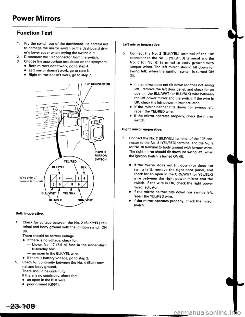
Function Test
1.Pry the switch out of the dashboard. Be careful notto damage the mirror switch or the dashboard driv-er's lower cover when prying the switch out.Disconnect the 10P connector from the switch.Choose the appropriate test dased on the symptom:. Both mirrors don't work, go to step 4.. Left mirror doesn't work, go to step 6.. Right mirror doesn't work, go to step 7.
Both inoperative:
4. Check for voltage between the No. 2 (BLVYEL) ter-minal and body ground with the ignition switch ON
fl r).
There should be baftery voltage,. lf there is no voltage, check for:- blown No. 17 (7.5 A) fuse in the under-dashfuse/relay box.- an open in the BLK,/YEL wire.. lf there is battery voltage, go to step 2.5. Check for continuity between the No. 4 {BLK) termi-nal and body ground.
There should be continuity.
lf there is no continuity, check for;. an open in the BLK wire.. poor ground (c551).
,
-.t-..------'-
23-108
Left mirror inoperative:
6. Connect the No. 2 {BLKI/EL) terminal of the ,l0p
connector to the No. 3 (YEUREDI terminal and theNo.5 (or No.6) terminal to body ground withjumper wires. The left mirror should tilt down (or
swing left) when the ignition switch is turned ON t).
lf the mirror doei not tilt down (or does not swingleft), remove the left door panel, and check for anopen in the BLUMHT (or BLU/BLK) wire betweenthe left power mirror and the switch. lf the wire isOK, check the left power mirror actuator,
lf the mirror neither tilts down nor swings left,repair the YEURED wire.
lf the mirror operates properly, check the mirrorswitch.
Right mirror inoperaiiva:
7. Connect the No. 2 {BLVYEL) terminat of the 1Op con-nector to the No. 3 (YEURED) terminal and the No. 9(or No. 8) terminal to body ground with jumper wires.The right mirror should tilt down (or swing left) whenthe ignition switch is turned ON l).
. lf the mirror does not tilt down (or does notswing left), remove the right door panel, andcheck for an open in the GRN,4TVHT (or yEUBLK)
wire between the right power mirror and theswitch. lf the wire is OK, check the right power
mtrror actuator.
. lf the mirror neither tilts down nor swings left.repair the YEURED wire.. lf the mirror operates properly, check the mirrorswitch.
www.emanualpro.com
Page 1269 of 1395
J-
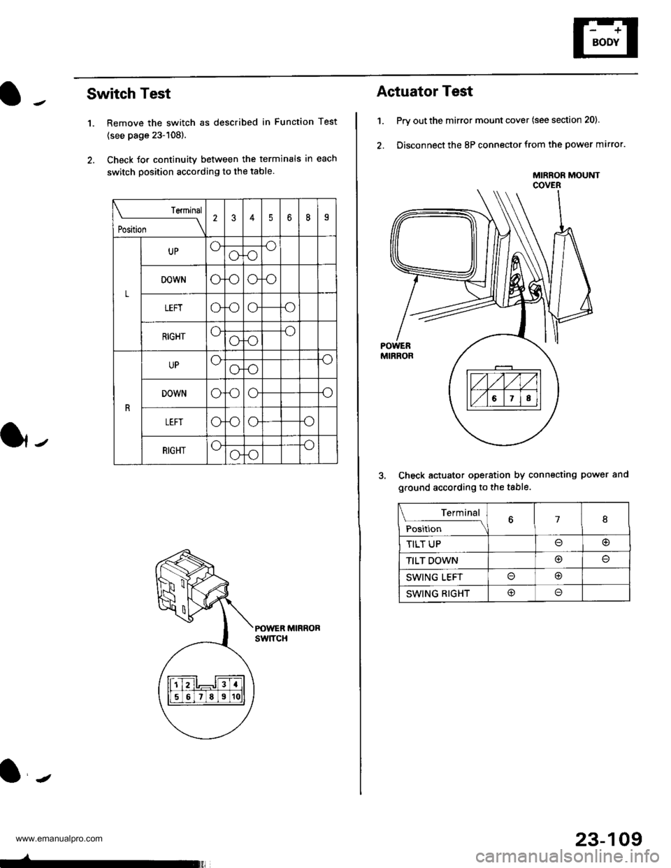
Switch Test
1. Remove the switch as described in Function Test
{see page 23-108).
2. Check Jor continuity between the terminals in each
switch position according to the table.
POWER MIRRORswtTcH
Teminal
t*t* \
2345b8I
L
UPoooo
DOWNoooo
LEFTo.ooo
RIGHToooo
R
UPoooo
DOWNoooo
oooo
RIGHToooo
23-109
Actuator Test
1. Prv out the mirror mount cover (see section 20).
2. Disconnect the 8P connector from the power mirror.
Check actuator operation by connecting power and
ground according to the table.
MIRROR MOUtrlTCOVER
Terminal
;;,i". -\18
TILT UP@
TILT DOWN@
SWING LEFTo@
SWING RIGHT@o
www.emanualpro.com
Page 1270 of 1395
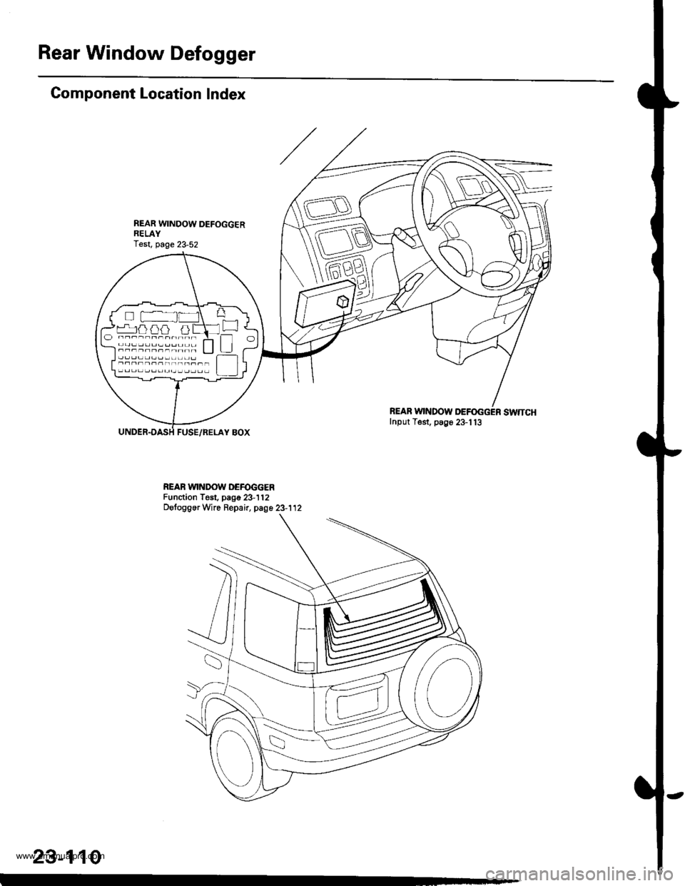
Rear Window Defogger
Gomponent Location Index
FUSE/RELAY BOX
REAB WINDOW DEFOGGER SWTTCHInput Test, p89e 23-113
REAR WINDOW DEFOGGERFunction Test. page 23-112DetoggerWre Repair, page 23-112
rr^ja} aia al Irl
!
23-110
www.emanualpro.com