Hose HONDA CR-V 2000 RD1-RD3 / 1.G Workshop Manual
[x] Cancel search | Manufacturer: HONDA, Model Year: 2000, Model line: CR-V, Model: HONDA CR-V 2000 RD1-RD3 / 1.GPages: 1395, PDF Size: 35.62 MB
Page 1160 of 1395
Gondenser
't.
Replacement
Recover the refrigerant with a recovery/recycling/
charging ststion (see page 22-59)
Remove the front grille (see section 20).
Remove the coolant reservoii, but do not discon-
nect the reservoir hose Jrom the coolant reservoir
and the radiator.
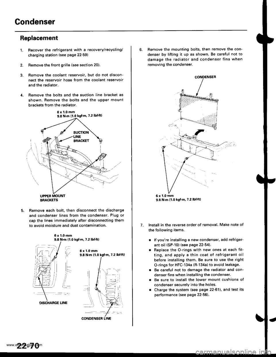
Remove the bolts and the suction line bracket as
shown. Remove the bolts and the upper mount
brsckets from the radiator.
UPPER MOUNTBRACKETS
Remove each bolt, then disconnect the discharge
and condenser lines from the condenser, Plug or
cap the lines immediately after disconnecting them
to avoid moisture and dust contamination.
6x1.0mm9.8 N.m 11,0 kgf.m, 7.2 lbfttl
t\,l/
ait- -:
i..
6x1.0mm
6xl.0mm9,8 N.m 11.0 kgf'm' 7.2lbf'ft)
22-70
DISCHARGE LINE
CONDENS€R LINE
6. Remove the mounting bolts, then remove the con-
denser by lifting it up as shown. Be careful not to
damage the radiator and condenser fins when
removing the condenser.
Install in the reverse order of removal. Make note of
the following items.
. lf you're installing a new condenser, add refriger-
ant oil (sP-10) (see page 22-54]..
o Replace the O-rings with new ones at each fit-
ting, and apply a thin coat of refrigerant oil
before installing them. Be sure to use the right
O-rings for HFC-134a (R-134a) to avoid leakage.
. Be careful not to damage the radiator and con-
denser fins when installing the condenser.
. Be sure to install the lower mount cushions of
condenser securely into the holes,
. Charge the system (see page 22-61), and test its
performance (see page 22-56).
7.
1,0 mm
www.emanualpro.com
Page 1164 of 1395
Troubleshooting
Tips and Precautions (cont'dl
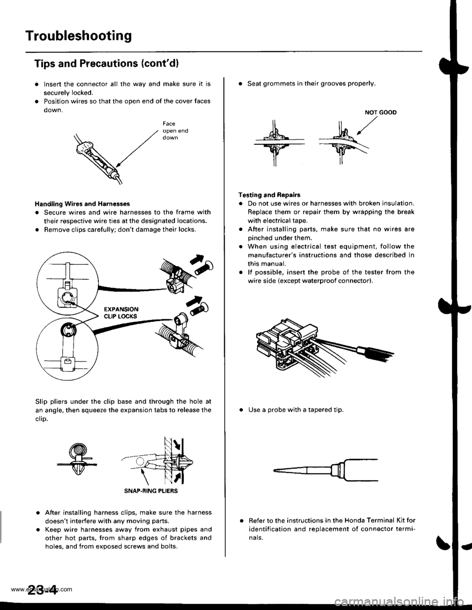
Insen the connector all the way and make sure it is
securely Iocked.
Position wires so that the open end of the cover faces
down.
V
Faceopen end
Handling Wires and Harnesges
. Secure wires and wire harnesses to the frame with
their respective wire ties at the designated locations.
. Remove clips carefully; don't damage their locks.
Slip pliers under the clip base and through the hole at
an angle, then squeeze the expansion tabs to release the
clrD.
After installing harness clips, make sure the harness
doesn't interfere with any moving pans.
Keep wire harnesses away from exhaust pipes and
other hot parts, trom sharp edges of brackets and
holes. and from exoos€d screws and bolts.
NOT GOOD
A -M/
lr lr*
T€sting and Repairs
. Do not use wires or harnesses with broken insulation.
Replace them or repair them by wrapping the break
with electricaltape.
. After installing parts, make sure that no wires are
pinched under them.
. When using electrical test equipment, follow the
manufacturer's instructions and those described in
this manual.
. lf possible, insert the probe of the tester from the
wire side (except waterproof connector).
. Seat grommets in their grooves properly.
. Use a probe with a tapered tip.
Refer to the instructions in the Honda Terminal Kit for
identification and replacement of connector termi-
nals.
www.emanualpro.com
Page 1280 of 1395
Wipers/Washers
1.
Rear Window Wiper Motor Test
Remove the tailgate trim panel (see section 20),
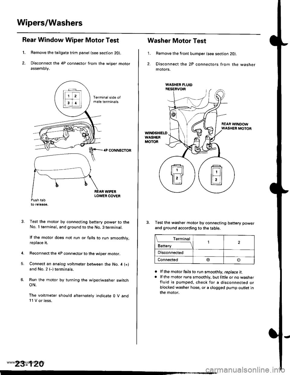
Disconnect the 4P connector from the wiper motor
assembly.
4P CONNECTOR
WIPEBLOWER COVEnPush tabto release,
Test the motor by connecting battery power to theNo. I terminal, and ground to the No. 3 terminal.
lf the motor does not run or fails to run smoothly,replace it.
Reconnect the 4P connector to the wiper motor.
Connect an analog voltmeter between the No. 4 (+)
and No. 2 (-) terminals.
Run the motor by turning the wiper/washer switchoN.
The voltmeter should alternately indicate 0 V and11 V or less.
4.
5.
23-120
1.
Washer Motor Test
Remove the front bumper (see section 20).
Disconnect the 2P connectors from the washermolors,
REAR WINDOWWASHER MOTOR
Test the washer motor by connecting battery power
and ground according to the table.
lf the motor fails to run smoothly, replace it.lf the motor runs smoothly, but little or no washerfluid is pumped, check for a disconnected orblocked washer hose, or a clogged pump outlet inthe motor.
a
a
L_Iq'.r91
Battery
,l
Disconnected
Connected@
www.emanualpro.com
Page 1291 of 1395
Transmitter Programming
Storing transmitter codes:
The codes of up to three transmitters can be read into
the kevless receiver unit memory (lf a fourth code is
stored. the code which was inDUt first will be erased.)
NOTE: lt is important to maintain the time limits
between the steps.
1.
11.
Turn the ignition switch ON (ll).
Within 1 to 4 sec., push the transmitter lock or unlock
button with the transmitter aimed at the vehicle.
Within 1 to 4 sec., turn the ignition switch OFF.
Within 1 to 4 sec., turn the ignition switch ON (ll).
Within 1 to 4 sec.. push the transmitter lock or
unlock button with the transmitter aimed at the
vehicle.
Within 1 to 4 sec., turn the ignition switch OFF.
Within 4 sec., turn the ignition switch ON {ll).
Within 1 to 4 sec., push the transmitter lock or
unlock button with the transmitter aimed at the
vehicle.
Within 1 to 4 sec., turn the ignition switch OFF,
Within 4 sec., turn the ignition switch ON (ll).
Within 1 to 4 sec., push the transmitter lock of
unlock button with the transmitter aimed at the
vehicle.
Confirm you can hear the sound of the door lock
aduators.
Within 8 sec., aim the transmitters (up to three)
whose codes you want to store at the receiver, and
press the transmitter lock or unlock buttons.
Confirm that you can hear the sound of the door
lock actuators after each transmitter code is stored.
Turn the ignition switch OFF, and pull out the key.
Confirm proper operation with the new code{sl.
-
o.
1.
9.
10.
12.
13.
14.
-
15.
23-131
www.emanualpro.com
Page 1394 of 1395
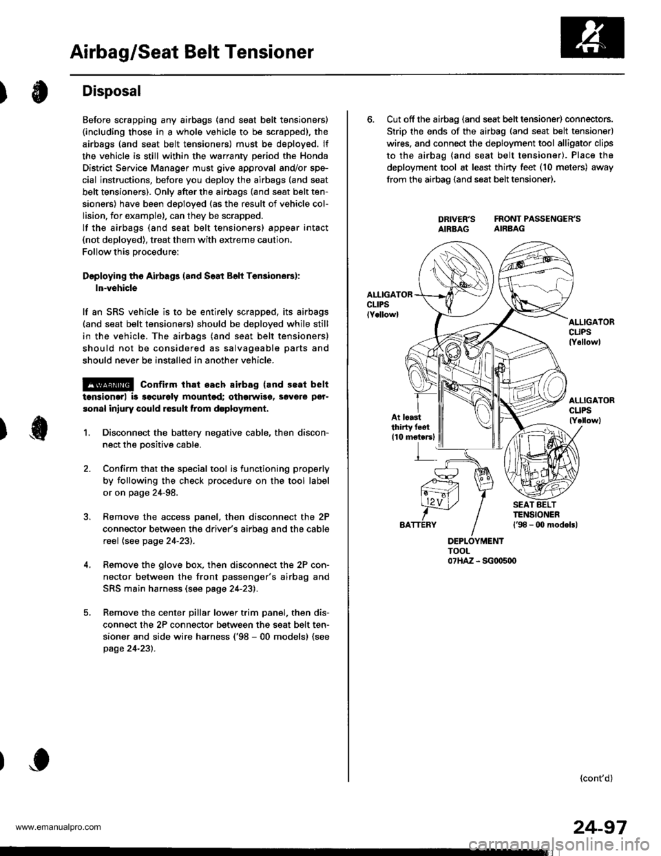
Airbag/Seat Belt Tensioner
)Disposal
)
Before scrapping any airbags {and seat belt tansioners)
(including those in a whole vehicle to be scrappedl. the
airbags (and seat belt tensioners) must be deployed. lf
the vehicle is still within the warrantv oeriod the Honda
District Service Manager must give approval and/or spe-
cial instructions, before you deploy the airbags (and seat
belt tensioners). Only after the airbags {and seat belt ten-
sioners) have been deployed (as the result of vehicle col-
lision, for example), can they be scrapped.
lf the airbags (and seat belt tensioners) appear intact
(not deployed), treat them with extreme caution.
Follow this procedure:
Doploying tho Airbags (and Soat B6li Ten3ione6):
ln-vehicle
lf an SRS vehicle is to be entirely scrapped, its airbags(and seat belt tensioners) should be deployed while still
in the vehicle. The airbags (and seat belt tensioners)
should not be considered as salvageable parts and
should never be installed in another vehicle.
@ confirm that each airbag {and seat belt
tonsiongr) i3 ggcurely mountod; othgrwise, severe per-
sonal iniury could result from d6ploym6nt,
1. Disconnect the battery negative cable, then discon-
nect the oositive cable.
Confirm that the special tool is functioning properly
by following the check procedure on the tool label
or on page 24-98.
Remove the access panel, then disconnect the 2P
connector between the driver's airbag and the cable
reel (see page 24-23).
Remove the glove box, then disconnect the 2P con-
nector between the front passenger's airbag and
SRS main harness (see page 24-23).
Remove the center pillar lower trim panel, then dis-
connect the 2P connector between the seat belt ten-
sioner and side wire harness ('98 - 00 models) (see
page 24-231.
6. Cut off the airbag (and seat belt tensioner) connectors.
Strip the ends of the airbag (and seat belt tensioner)
wires. and connect the deployment tool alligator clips
to the airbag (and seat belt tensioner). Place the
deployment tool at least thirty feet (10 meters) away
from the airbao (and seat belt tensioner),
DRIVER'S FRONTPASSENGER'SAIBBAG AIRBAG
AI.IIGATORcuPslY6llowl
At lcastthirty feot
110 motersl
(cont'd)
24-97
www.emanualpro.com