Reverse HONDA CR-V 2000 RD1-RD3 / 1.G Workshop Manual
[x] Cancel search | Manufacturer: HONDA, Model Year: 2000, Model line: CR-V, Model: HONDA CR-V 2000 RD1-RD3 / 1.GPages: 1395, PDF Size: 35.62 MB
Page 1074 of 1395
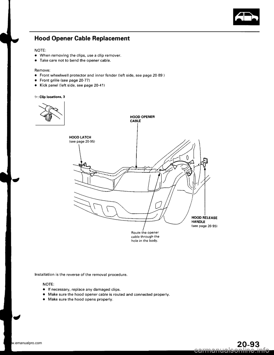
Hood Opener Cable Replacement
NOTE:
. When removing the clips, use a clip remover.
. Take care not to bend the opener cable.
Remove:
. Front wheelwell protector and inner fender {left side, see page 20 89}
. Front grille (see page 20-77)
. Kick panel (left side. see page 20-411
HOOD LATCH(see page 20-95)
Route the openercable through thehole in the body.
>: Clip locations,3
'.--)r I
@l
Installation is the reverse of the removal procedure.
NOTE:
. lf necessary. replace any damaged clips.
. Make sure the hood opener cable is routed and connected properly.
. Make sure the hood opens properly.
t"
HOOD RELEASEHANDLE(see page 20 95)
www.emanualpro.com
Page 1075 of 1395
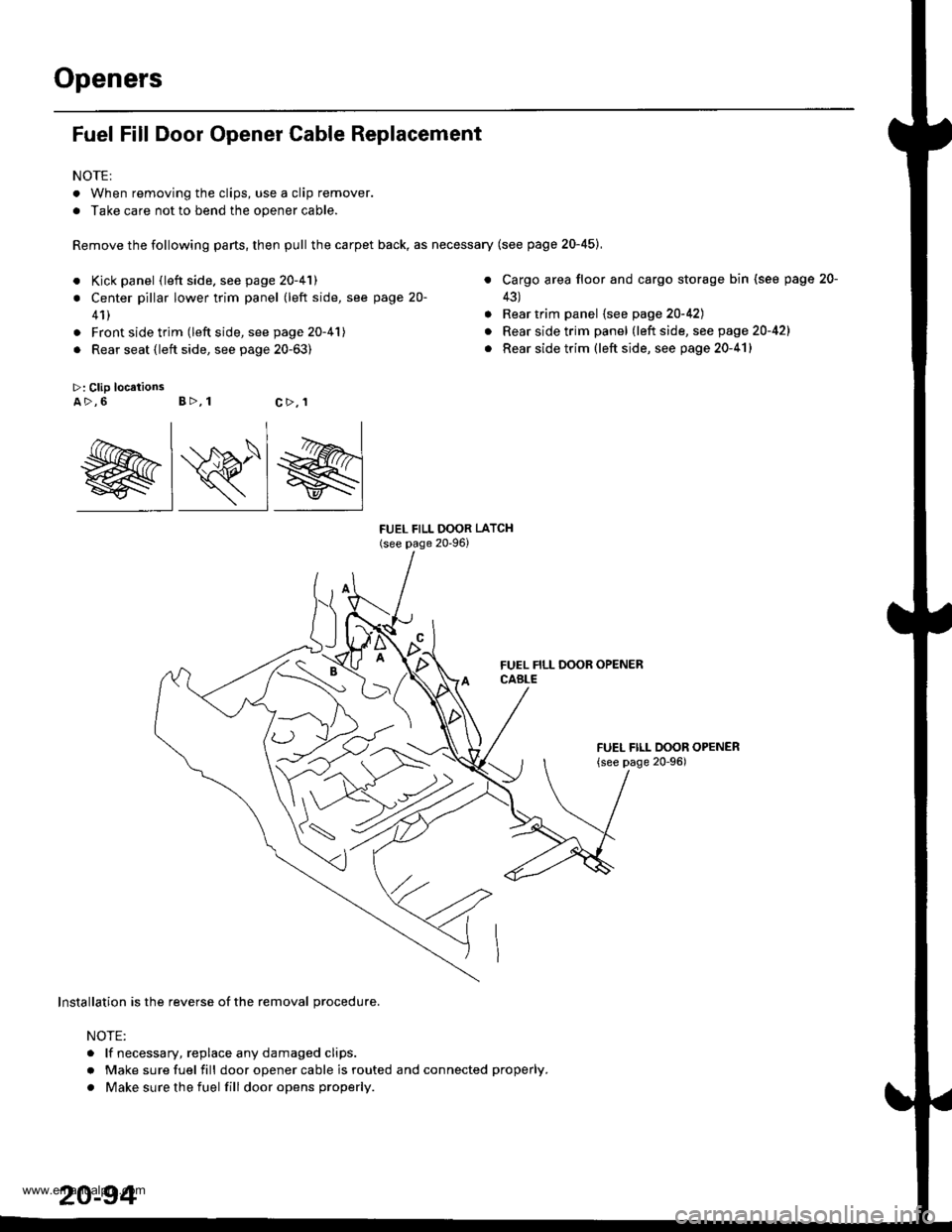
Openers
Fuel Fill Door Opener Cable Replacement
NOTE:
. When removing the clips, use a clip remover.
. Take care not to bend the opener cable.
Remove the following parts, then pull the carpet back, as necessary (see page 20-45),
a
>: Clip locationsA>,6 B>, 1
a
a
FUEL FILL OOOR LATCH(see page 20-96)
Kick panel (left side. see page 20-41)
Center pillar lower trim panel (left side, see page 20-
41)
Front side trim (left side, see page 20-41)
Rear seat (left side, see page 20-63)
Cargo area floor and cargo storage bin (see page
43)
Rear trim panel {see page 20-42)
Rear side trim panel (left side, see page 20-421
Rear side trim (left side, see page 20-41)
FUEL FILL DOOR OPENER
{see page 20-96)
20-
c>,1
@lRlg
Installation is the reverse of the removal procedure.
NOTE:
. lf necessary, replace any damaged clips.
r Make sure fuel fill door opener cable is routed and connected properly.
. Make sure the fuel fill dooropens properly.
www.emanualpro.com
Page 1076 of 1395
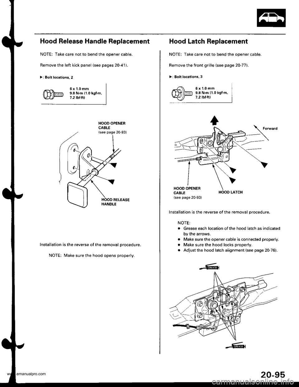
Hood Release Handle Replacement
NOTE: Take care not to bend the opener cable.
Remove the left kick panel (see pages 20-41).
>: Eolt locations.2
6x1.0mm9.8 N.m {1.0 kgl.m,7.2 tbl.tll
HOOD OPENERCABLE{see page 20-93)
Installation is the reverse of the removal procedure.
NOTE: Make sure the hood opens properly.
Hood Latch Replacement
NOTE: Take care not to bend the opener cable.
Remove the front grille (see page 20-77).
>: Bolt locations,3
6x1.0mm9.8 N.m {1.0 kgf.m,7.2 tbt.ftl
HOOO LATCH
Installation is the reverse of the removal procedure.
NOTE;
. Grease each location ofthe hood latch as indicated
by the arrows.
. Make sure the opener cable is connected properly.
. Make sure the hood locks properly.
. Adjust the hood latch alignment (see page 20-76).
20-95
www.emanualpro.com
Page 1077 of 1395
Openers
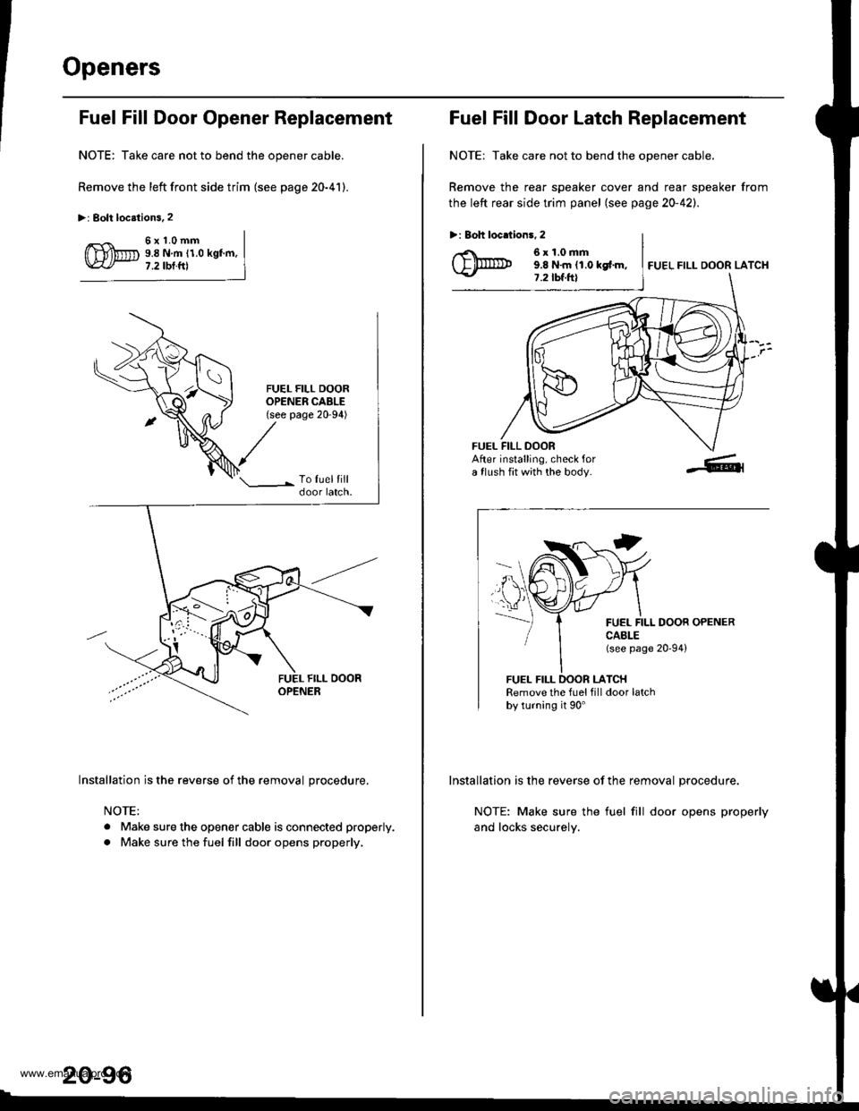
Fuel Fill Door Opener Replacement
NOTE: Take care not to bend the opener cable.
Remove the left front side trim (see page 20-41).
>: Bolt locstions.2
5x1.0mm9.8 N.m (1.0 kgf.m,7.2 tbt.ftl
FUEL FILL DOOROPENER CABLE(see page 20-94)
Installation is the reverse of the removal procedure.
NOTE:
. Make sure the opener cable is connected properly.
. Make sure the fuel fill door opens properly,
20-96
Fuel Fill Door Latch Reolacement
NOTE: Take care not to bend the opener cable.
Remove the rear speaker cover and rear speaker from
the left rear side trim panel (see page 20-42).
>: Boh locdions, 2
6x1.0mm9.8 N.m (1.0 kgf.m,7.2 tbf.ft)FUEL FILL DOOR LATCH
FUEL FILL DOORAfter installing, check fora flush fit with the body.
CAELE(see Page
LATCH
DOOR OPENER
20,94)
FUEL
FUEL FILLRemove the fuel fill door latchby turning it 90'
Installation is the reverse of the removal procedure.
NOTE: Make sure the fuel fill door opens properly
and locks securely.
www.emanualpro.com
Page 1079 of 1395
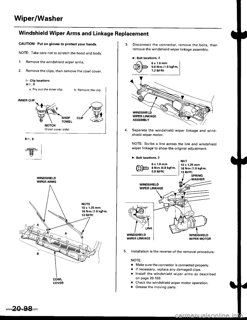
Wiper/Washer
Windshield Wiper Arms and Linkage Replacement
CAUTION: Put on gloves to protoct your hands.
NOTE: Take care not to scratch the hood and body.
1. Remove the windshield wiper arms.
2. Remove the clips, then remove the cowl cover.
>: Clip locationsA>.9
b. Remove the clip.
SHOPTOWEL
(Cowl cover side)
/G
"rr/ &
a. Pry out the anner clip.
INNER CLIP
B>.8
ql
WINDSHIELDWIPER ARMS
NUTS'10 x 1.25 mm18 N.m 11.8 kgf.m.13 tbf.ftl
COVER
20-98
3. Disconnect the connector, remove the bolts, then
remove the windshield wiper linkage assembly.
>: Boh locations,3
4. Separate the windshield wiper linkage and wind-shield wiper motor.
NOTE: Scribe a line across the link and windshieldwiper linkage to show the original adjustment.
>: Boh locations, 3
s}@
1ffi,
/Y{
/
' L|NK
WINDSHIELDWIPER LIN(AGEWIPER MOTOR
5. Installation is the reverse of the removal procedure.
NOTE:
. Make sure the connector is connected properly.. lf necessary. replace any damaged clips.. Install the windshield wiper arms as describedon page 20-103.
. Check the windshield wiper motor operation.. Grease the moving parts.
6x1.0mm9.8 N.m (1.0 kglm,7.2 tbt.fr)
6x1.0mm8 N.m 10.8 kgf.m,5.8 lbf.ftl
NUT10 x 1.25 mm18 N.m 11.8 kgf.m,13 tbf.ftlSPRINGWASHER
www.emanualpro.com
Page 1080 of 1395
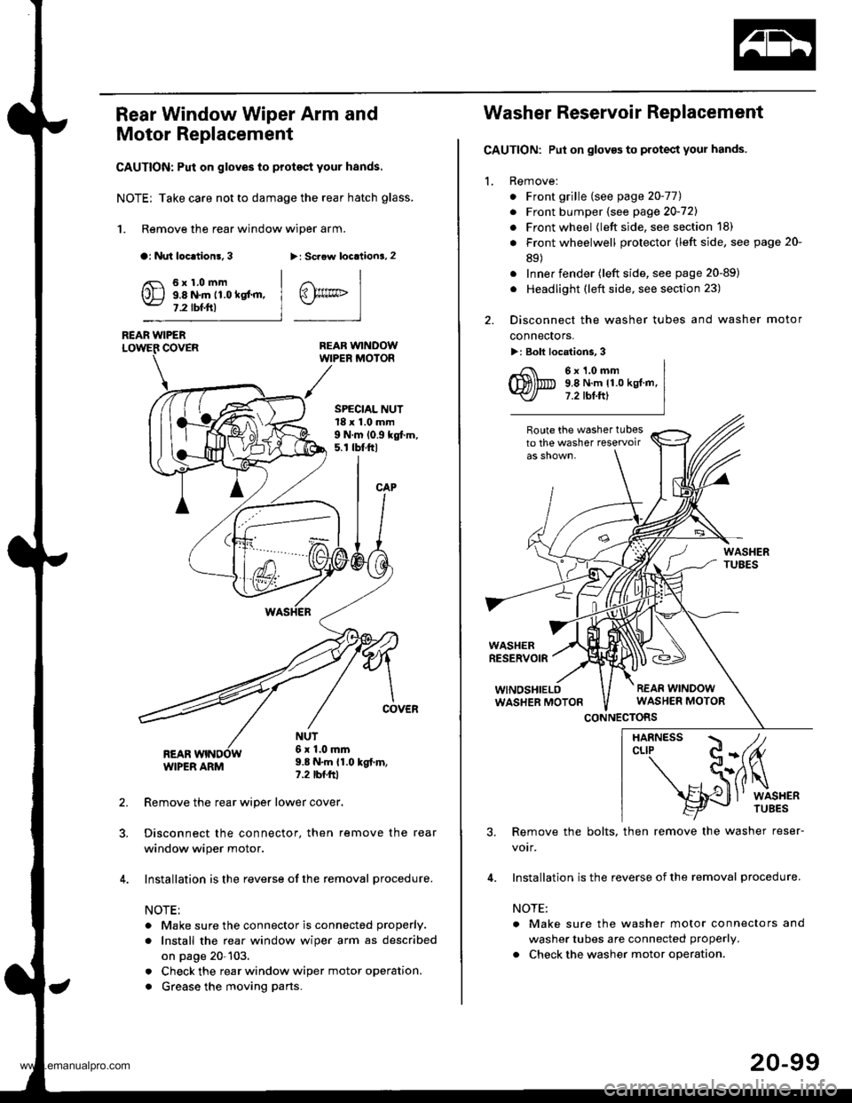
Rear Window Wiper Arm and
Motor Replacement
CAUTION: Put on gloves to protect your hands.
NOTE; Take care not to damage the rear hatch glass.
1. Remove the rear window wiper arm.
a: Nut loc.tion!, 3>: Scaow locationa, 2
REAR WINDOWWIPER MOIOR
REAR WIPERCOVER
REARWIPER ARM
6x1.0mm9.8 N.m 11.0 kgt'm,7.2 tbf.ftl
SPECIAL NUT18 x 1.0 mm9 N.m 10.9 kgt m,5. r tbt.ftl
NUT6x 1.0mm9.8 N.m {1.0 kgt.m,?.2 tbfftl
Remove the rear wiper lower cover.
Disconnect the connector, then remove the rear
window wiper motor.
Installation is the reverse of the removal procedure.
NOTE:
. Make sure the connector is connected properly.
. Install the rea. window wiper arm as described
on page 20-103.
. Check the rear window wiper motor operation.
. Grease the moving parts.
@rrc
Washer Reservoir Replacement
GAUTION: Put on gloves to protect your hands.
1. Remove:
. Front grille (see page 20-771
. Front bumper (see page 20-721
. Front wheel {left side, see section 18)
. Front wheelwell protector (left side, see page 20-
89)
. Inner fender (left side, see page 20-89)
. Headlight (left side, see section 23)
2. Disconnect the washer tubes and washer motor
connectors.
>: Bolt locations, 3
6x1.0mm9,8 N.m 11.0 kgt.m,7.2 tbt.ftl
Route the washer tubesto the washer teservoir
WASHERRESERVOIR
WINOSHIELOWASHER MOTON
CONNECTORS
3. Remove the bolts, then remove the washer reser-
votr,
4. Installation is the reverse of the removal procedure.
NOTE:
a Make sure the washer motor connectors and
washer tubes are connected properly.
. Check the washer motor operation.
HARNESS / tcLrP C-(fu
- S(ilq
s{J
l' wrsHER
20-99
www.emanualpro.com
Page 1081 of 1395
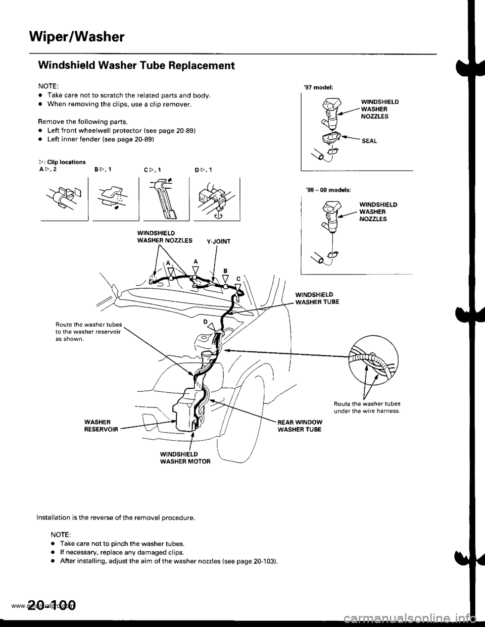
Wiper/Washer
Windshield Washer Tube Replacement
NOTE:
. Take care not to scratch the related parts and body.. When removing the clips, use a clip remover.
Remove the following parts.
. Left front wheelwell protector (see page 20-89). Left inner fender (see page 20-89)
WINDSHIELOWASHER NOZZLES Y-JOINT
Boute the w6sher tubesto the washer reservoir
'97 model:
63'fr{-------
ax---\J
,.&--
\7>: Clip locationsA >,2 B >,1c>, 1D>,1
\
lnstallation is the reverse of the removal procedure.
NOTE:
. Take care not to pinch the washer tubes.
. lf necessary, replace any damaged clips.. After installing, adjust the aim ofthe washer nozzles (see page 20-103).
20-100
www.emanualpro.com
Page 1083 of 1395
Wiper/Washer
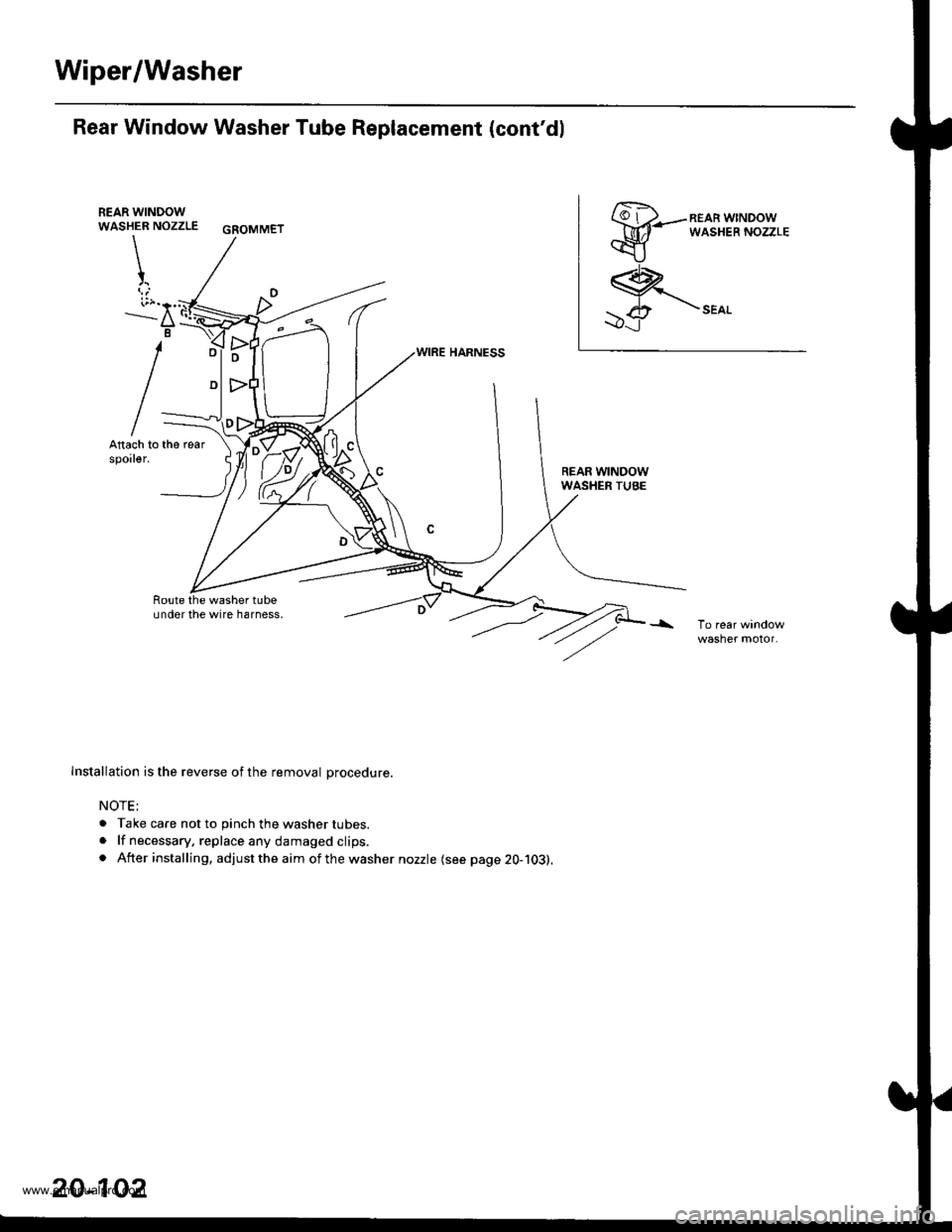
Rear Window Washer Tube Replacement (cont'dl
REAR WINDOWWASHER NOZZLE GSOMMET
\
t
i;r."'..--a
B
REAR WINDOWWASHER TUBE
Route the washer tubeundor the wire harness,
Installation is the reverse of the removal Drocedure.
NOTE;
. Take care not to pinch the washer tubes.. lf necessary, replace any damaged clips.. After installing, adjust the aim of the washer nozzle (see page 20-103).
20-102
www.emanualpro.com
Page 1131 of 1395
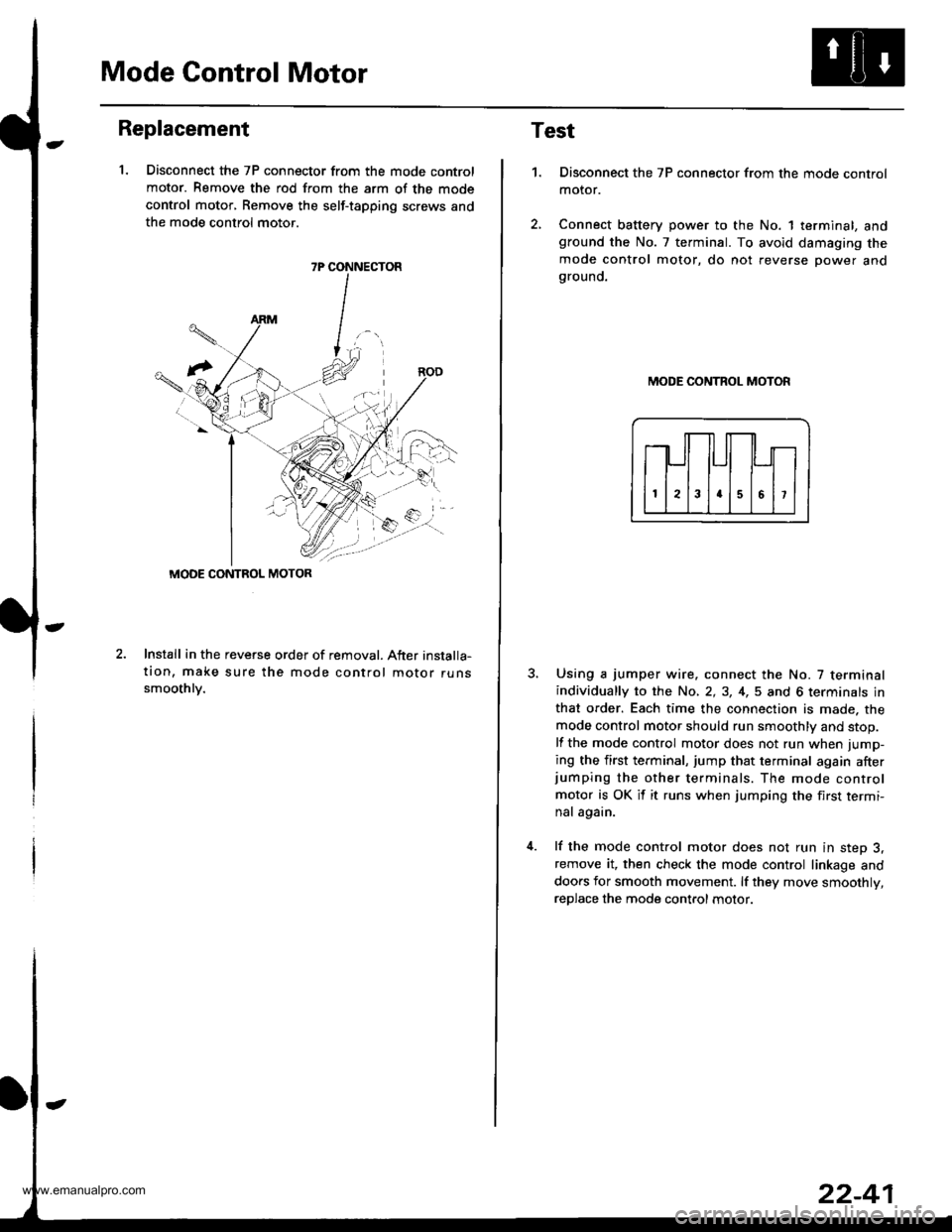
Mode Control Motor
Replacement
1. Disconnect the 7P connector from the mode control
motor. Remove the rod from the arm of the mode
control motor, Remove the self-tapping screws and
the mode control motor.
2.Install in the reveGe order of removal. After installa-
tion, make sure the mode control motor runssmoothlv.
7P CONNECTOR
MODE CONTROL MOTOR
Test
1.Disconnect the 7P connector from the mode control
motor.
Connect battery power to the No. 1 terminal, andground the No. 7 terminal. To avoid damaging the
mode control motor, do not reverse power andgrouno.
MODE CONTROL MOTOR
Using a jumper wire. connect the No. 7 terminalindividually to the No, 2,3, 4,5 and 6 terminals in
that order. Each time the connection is made. the
mode control motor should run smoothly and stop.
lf the mode control motor does not run when jump-
ing the first terminal, jump that terminal again afterjumping the other terminals. The mode control
motor is OK it it runs when jumping the first termi-
nal again.
lf the mode control motor does not run in step 3,remove it, then check the mode control linkage and
doors for smooth movement. lf they move smoothly,
reDlace the mode control motor.
www.emanualpro.com
Page 1132 of 1395
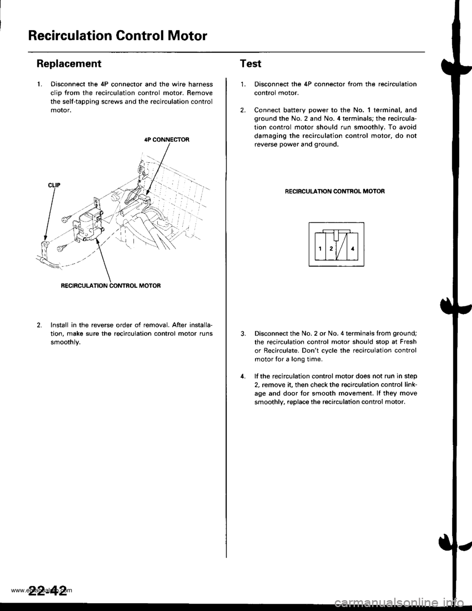
Recirculation Control Motor
Replacement
1. Oisconnect the 4P connector and the wire harness
clio from the recirculation control motor. Remove
the self-tapping screws and the recirculation control
motor,
lnstall in the reverse order of removal. After installa-
tion, make sure the recirculation control motor runs
smoothlv.
{P CONNECTOR
22-42
Test
1.
4.
Disconnect the 4P connector from the recirculation
control motor.
Connect battery power to the No. 1 terminal, and
ground the No. 2 and No. 4 terminals; the recircula-
tion control motor should run smoothly. To avoid
damaging the recirculation control motor. do not
reverse power and ground.
RECIRCULANON CONTROL MOTOR
Disconnect the No. 2 or No. 4 terminals from ground;
the recirculation control motor should stop at Fresh
or Recirculate. Don't cvcle the recirculation control
motor for a long time.
lf the recirculation control motor does not run in step
2, remove it, then check the recirculation control link-
age and door for smooth movement. lf they move
smoothly, replace the recirculation control motor.
www.emanualpro.com