housing HONDA CR-V 2000 RD1-RD3 / 1.G Workshop Manual
[x] Cancel search | Manufacturer: HONDA, Model Year: 2000, Model line: CR-V, Model: HONDA CR-V 2000 RD1-RD3 / 1.GPages: 1395, PDF Size: 35.62 MB
Page 873 of 1395
Power Steering Pump
Reassembly
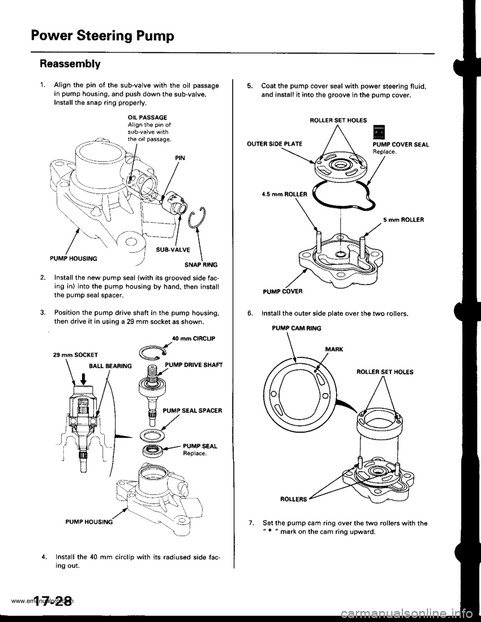
'1.Align the pin of the sub-valve with the oil passage
in pump housing, and push down the sub-valve.
Install the snsp ring properly.
OIL PASSAG€Align the pin of
the oil passage.
#q
;1..*
\SNAP RINGPUMP HOUSING
Install the new pump seal (with its grooved side fac-
ing in) into the pump housing by hand, then install
the pump seal spacer.
Position the pump drive shaft in the pump housing,
then drive it in using a 29 mm socket as shown,
BALL BEARfNG grlu,e un.t
/ /ffi\
1 / t\v4
t/ Y
# I F
PUMP SEALSPAC,ER
ry^
i- d
,O mm CIRCLIP
Hgo
/= PUMP DRIVE SHAFT
@.--#$i":*'
4,
PUMP HOUSING
Install the 40 mm circlip with its radiused side fac-
Ing out.
29 mm SOCKET
17 -2A
7.
5. Coat the pump cover seal with power steering fluid,
and install it into the groove in the pump cover.
OUTER SIDE PLATE
5 mrh ROLLER
lnstall the oute. side plate over the two rollers.
PUMP CAM RING
ROLLER SET HOLES
ROLLERS
Set the pump cam ring over the two rollers with the"' " mark on the cam ring upward.
ROLLER SET HOLES
PUMP COVER
www.emanualpro.com
Page 874 of 1395
8.
9.
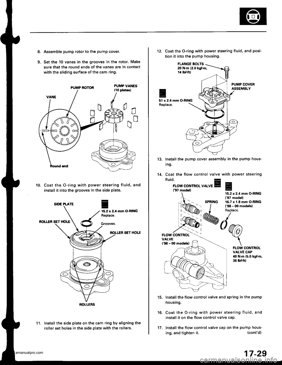
Asssmble pump rotor to the pump cover,
Set the 10 vanes in the grooves in the rotor, Make
sure that the round ends of the vanes are in contact
with the sliding surface of the cam ring.
PUMP ROTOR
Coat the O-ring with power steering fluid, and
install it into the grooves in the side plate.
ftm GRING
ROL1IR SET HOI,E
SET HOTT
Install the side plate on the cam ring by aligning the
roller set holes in the side Dlate with the rollers.
10.
I
15.2 x 2-1Replace.
Gfooves.
SII'E PLATE
BOLI-ERS
11.
17.
ing, and tighten it.
12. Coat the O-ring with power steering fluid,
tion it into the pump housing.
and posi-
FLANGE BOI-TS20 N.m (2.0 kgt m,14 tbf.ft)
51 x 2.4 mm O-RINGReplace.
13.
14.
lnstall the
ing.
Coat the
fluid.
pump cover assembly in the pump hous-
tlow control valve with power steering
FLOW CONTROL VALVE137 modol)
FLOW CONTBOLVALVEl'98 - 0O modeltl
'15.
16.
Install the flow control valve and spring in the pump
housing.
Coat the O-ring with power steering fluid, and
install it on the flow control valve cap.
Install the flow control valve cap on the pump hous-
Eg
SPRING
15.2 x 2.4 mm O.RING('97 modell16.7 x'1.8 mm O-RING
FLOW CONTROLVALVE CAP49 N.m (5.0 kgl.m,36 tbf.ft)
(cont'd)
17-29
www.emanualpro.com
Page 875 of 1395
Power Steering Pump
Reassembly (cont'dl
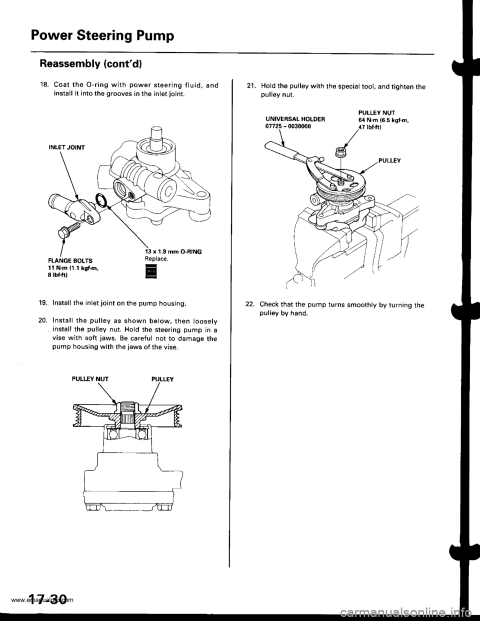
'18. Coat the O-ring wjth power steering fluid, andinstall it into the grooves in the inlet joint.
FLANGE BOLTS11 N.m 11.1 kgf.m,8 rbf.ft)
'13 x '1.9
Replace.r
E
19.
20.
Install the inlet joint on the pump housing.
Install the pulley as shown below. then loosely
install the pulley nut. Hold the steering pump in avise with soft jaws. Be careful not to damage thepump housing with the jaws of the vise.
17-30
21. Hold the pulley with the speciat toot, and tighten thepulley nut.
Check that the pump turns smoothly by turning thepulley by hand.
www.emanualpro.com
Page 881 of 1395
Power Steering Gearbox
Disassembly {cont'd}
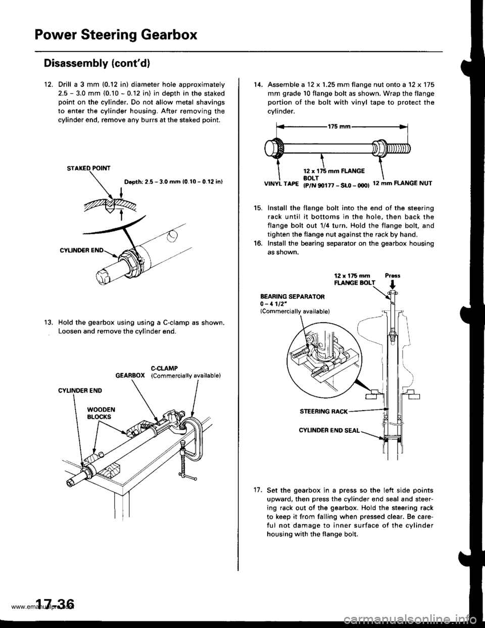
12. Drill a 3 mm (0.12 in) diameter hole approximately
2.5 - 3.0 mm (0.10 - 0.12 in) in depth in the staked
point on the cylinder. Do not allow metal shavings
to enter the cylinder housing. After removing the
cylinder end, remove any burrs at the staked point.
D.oth: 2.5 - 3.0 mm 10.10 - 0.12 inl
CYUNOER
Hold the gearbox using using a C-clamp as shown,
Loosen and remove the cvlinder end.
13.
17-36
14, Assemble a 12 x 1.25 mm flange nut onto a '12 x 175
mm grade 10 flange bolt as shown, Wrap the flange
portion of the bolt with vinyl tape to protect the
cvlinder,
VINYL TAP€ tp/N 90177 - SLO - OOOI 12mmFLANGENUT
Install the flange bolt into the end of the steering
rack until it bottoms in the hole. then back the
flange bolt out 1/4 turn. Hold the flange bolt, and
tighten the flange nut against the rack by hand.
Install the bearing separator on the gearbox housing
as snown.
15.
BEARING SEPARATOR0 - 1112'(Commercially available)
17.
STEERING RACK
CYLINDER €ND
Set the gearbox in a press so the lelt side points
upward, then press the cylinder end seal and steer-
ing rack out of the gearbox. Hold the steering rack
to keep it from falling when pressed clear. Be care-
ful not damage to inner surface of the cylinder
housing with the flange bolt.
www.emanualpro.com
Page 883 of 1395
Power Steering Gearbox
Disassembly (cont'd)
Valve Body Unit Dbassembly
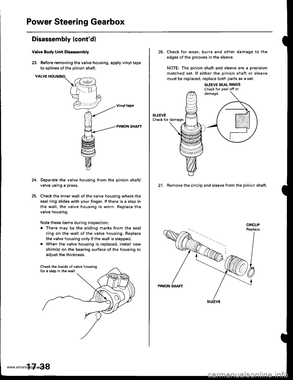
23. Before removing the valve housing, apply vinyltape
to solines of the Dinion shaft.
VALVE HOUSING
Separate the valve housing from the pinion shafv
valve using a press.
Check the inner wall of the valve housing where the
seal ring slides with your finger. lf there is a step in
the wall, the valve housing is worn. Replace the
valve housing.
Note these items during inspection:
o There may be the sliding marks from the seal
ring on the wall of the valve housing. Replace
the valve housing only if the wall is stepped.
. When the valve housing is replaced, install new
shim{s) on the bearing surface of the housing to
adiust the thickness.
Check the inside ofvalve housingfor a step in the wall.
17-38
26. Check for wear, burrs and other damage to the
edges of the grooves in the sleeve.
NOTE: The pinion shaft and sleeve are a precision
matched set. lf either the oinion shaft or sleeve
must be replaced, replace both parts as a set.
SLEEVE SEAL RINGSCheck for Deel off or
27. Remove the circlip and sleeve from the pinion shaft.
www.emanualpro.com
Page 884 of 1395
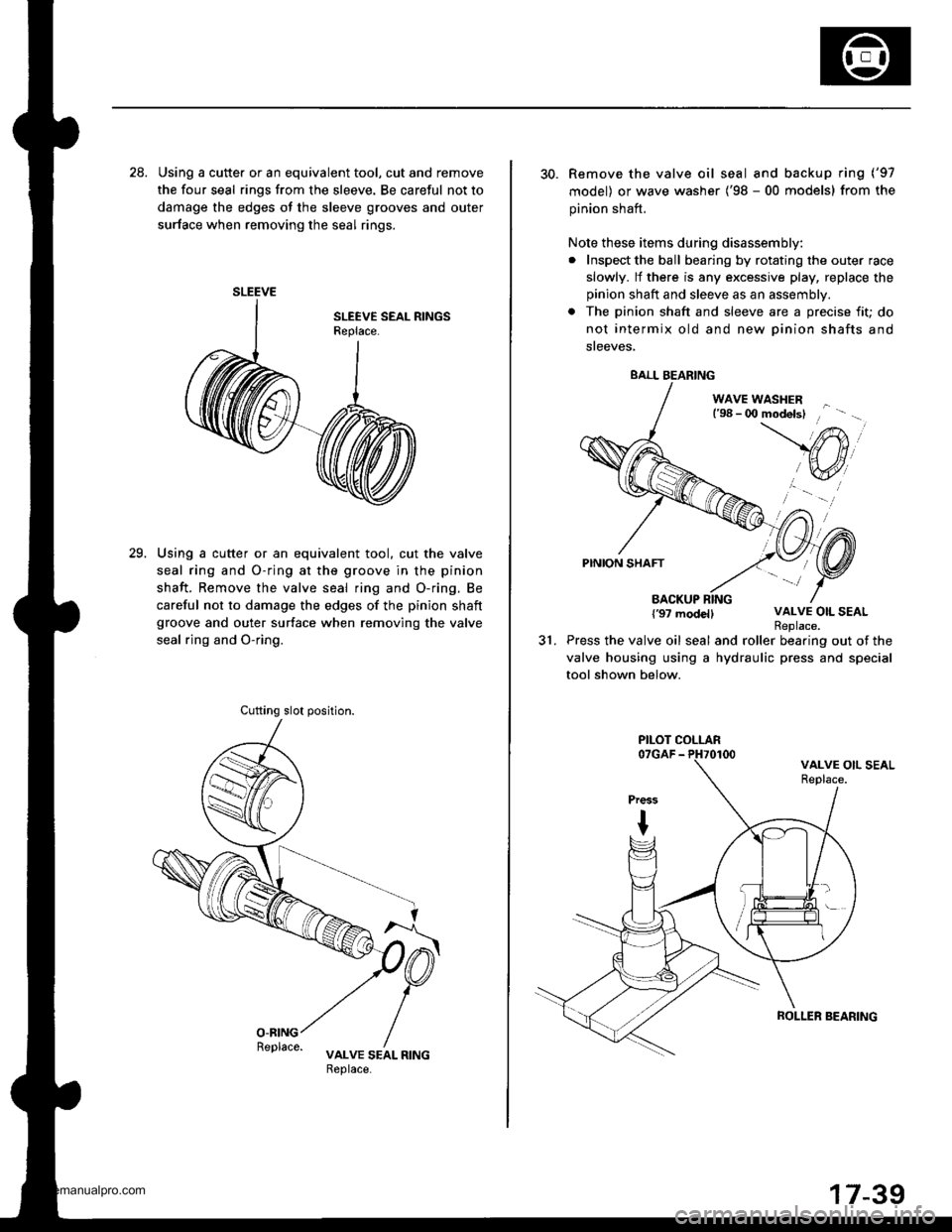
28. Using a cutte. or an equivalent tool, cut and remove
the four seal rings from the sleeve. Be careful not to
damage the edges ot the sleeve grooves and outer
surface when removing the seal rings.
Using a cutter or an equivalent tool. cut the valve
seal ring and O-ring at the groove in the pinion
shaft. Remove the valve seal ring and O-ring. Be
careful not to damage the edges of the pinion shaft
groove and outer surface when removing the valve
seal rjng and O-ring.
29.
SLEEVE
Cufting slot position.
30. Remove the valve oil seal and backup ring ('97
model) or wave washer ('98 - 00 models) from the
pinion shaft.
Note these items during disassembly:
. Inspect the ball bearing by rotating the outer race
slowly. lf there is any excessive play, replace the
pinion shaft and sleeve as an assembly.
. The pinion shaft and sleeve are a precise fit; do
not intermix old and new Dinion shafts and
sreeves,
WAVE WASHERl'98 - 0O modelsl
PINION SHAFT
BACKUP RING{'97 modellVALVE OIL SEAL
31.Replace.Press the valve oil seal and roller bearing out of the
valve housing using a hydraulic press and special
tool shown below.
BALL BEARING
PILOT COLLAR
ROLLER SEARING
www.emanualpro.com
Page 885 of 1395
Power Steering Gearbox
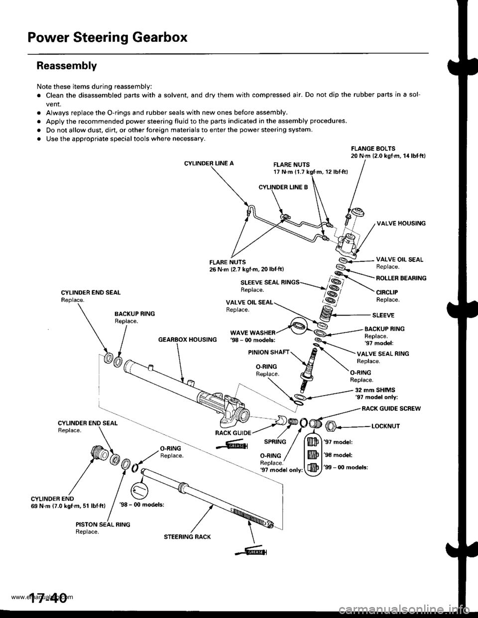
Reassembly
Note these items during reassembly
. Clean the disassembled parts with a solvent, and dry them with compressed air. Do not dip the rubber parts in a sol-
vent.
. Always replace the O-rings and rubber seals with new ones before assembly.
. Apply the recommended power steering fluid to the parts indicated in the assembly procedures.
. Do not allow dust. dirt, or other toreign materials to enter the power steering system.
. Use the appropriate specialtools where necessary.
FLANGE BOLTS20 N.m (2.0 kgl.m, 14lbtftl
CYLINDER LINE AFLARE NUTS17 N.m 11.712 rbl.ftl
VALVE HOUSING
CYLINDER END SEALReplace.
VALVE OIL SEALBeplace.
ROLLER BEARING
CIRCLIPReplace.
BA.KUP RING
\/^"
WAVE WASHERBACKUP RINGReplace.97 model:HOUSING
VALVE SEAL RINGReplace.
O.RINGReplace.
32 mm SHIMS'97 mod6l only:
RACK GUIDE SCREW
O-RINGReplace.
@---r-ocxr'rur
'97 model:
'98 model:
'99 - 0O mod6ls:'9? model only:
CYLINDER END69 N.m (7.0 kgf.m, 51 lbf.ft)'98 - (x) models:
PISTON SEAL RINGReplace.
17-40
STEERING RACK
www.emanualpro.com
Page 888 of 1395
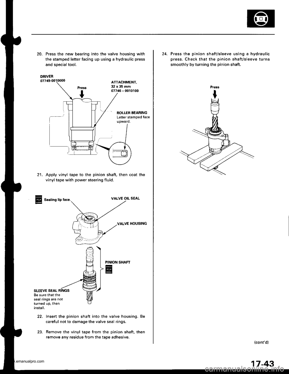
20. Press the new bearing into the valve housing with
the stamped letter facing up using a hydraulic press
and soecialtool.
ATTACHMENT,32x35mm07746 - 0010100
- ROLLER BEARINGLetter stamped face
21. Apply vinyl tape to the pinion shaft, then coat the
vinyltape with power steering fluid.
Sealing lip tace.VALVE OIL SEAL
VALVE HOUSING
SHAFT
SLEEVE SEAL
PINION
E
22, Insert the pinion shaft into the valve housing. Be
careful not to damage the valve seal rings.
23. Remove the vinyl tape from the pinion shaft, then
remove any residue from the tape adhesive.
8e sure that theseal rings are notturned up, theninstall.
DRIVER
24. Press the pinion shaft/sleeve using a hydraulic
press. Check that the pinion shaft/sleeve turns
smoothly by turning the pinion shaft,
(cont'd)
17-43
www.emanualpro.com
Page 890 of 1395
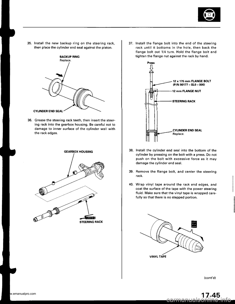
35. Install the new backup ring on the steering rack,
then place the cylinder end seal against the piston.
BACKUP RINGReplace.
Grease the steering rack teeth, then insert the steer-
ing rack into the gearbox housing, Be careful not to
damage to inner surface of the cylinder wall with
the rack edges.
to.
GEARBOX HOUSING
Prers
37. Install the flange bolt into the end of the steering
fack until it bottoms in the hole, then back the
flange bolt out 1/4 turn. Hold the flange bolt and
tighten the flange nut against the rack by hand.
12 x'175 mm FLANGE BOLT
lP/N 90177 - SLo - 0001
12 mm FLANGE NUT
38.
CYLINDER END SEALReplace.
Install the cylinder end seal into the bottom of the
cylinder by pressing on the bolt with a press, Do notpush on the bolt with excessive force as it may
damage the cylinder end seal.
Remove the flange bolt, and center the steering
rack.
Wrap vinyl tape around the rack end edges, and
coat the surface of the tape with the power steering
fluid. Make sure that the vinyl tape is wrapped care-
fully so that there is no stepped portion.
(cont'dl
ia
40.
17-45
www.emanualpro.com
Page 891 of 1395
Power Steering Gearbox
Reassembly (cont'dl
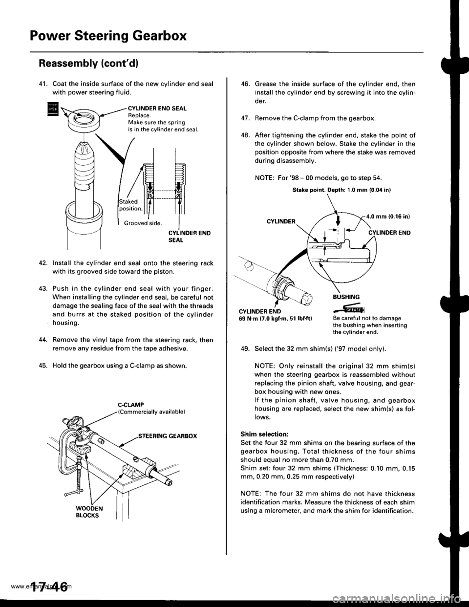
4l. Coat the inside surface of the new cvlinder end seal
with power steering fluid.
CYLINDEB ENO SEALReplace.Make sure the springis in the cylinder end seal.
43.
Stakedposrtron.
Grooved side.
42. Install the cylinder end seal onto the steering rack
with its grooved side toward the piston.
Push in the cylinder end seal with your finger.
When installing the cylinder end seal, be careful not
damage the sealing face of the seal with the threads
and burrs at the staked position of the cylinder
housing.
Remove the vinyl tape from the steering rack, then
remove any residue from the tape adhesive.
Hold the gearbox using a C-clamp as shown.
GEARBOX
44.
45.
C.CLAMP
17-46
46.Grease the inside surtace of the cylinder end, then
install the cylinder end by screwing it into the cylin-
der.
Remove the C-clamp from the gearbox.
After tightening the cylinder end, stake the point of
the cylinder shown below. Stake the cylinder in the
position opposite from where the stake was removed
during disassembly,
NOTE: For '98 - 00 models, go to step 54.
41.
48.
BUSHING
-tGCYLINDER END69 N.m (7.0 kgf.m,51 lbtft)8e careful not to damagethe bushing when insertingthe cylinder end.
49. Select the 32 mm shim(s) ('97 model onlv).
NOTE: Only reinstall the original 32 mm shim(s)
when the steering gearbox is reassembled without
replacing the pinion shaft. valve housing, and gear-
box housing with new ones.
lf the pinion shaft, valve housing, and gearbox
housing are replaced, select the new shim{s) as fol-
lows.
Shim selection:
Set the four 32 mm shims on the bearing surface of the
gearbox housing. Total thickness of the four shims
should equal no more than 0.70 mm.
Shim set: four 32 mm shims (Thickness: 0.10 mm, 0.15
mm, 0.20 mm, 0.25 mm respectively)
NOTE: The four 32 mm shims do not have thickness
identification marks. Measure the thickness of each shim
using a micrometer, and mark the shim for identification.
Stake point, Depth: 1,0 mm (0.04 inl
4.0 mm {0.16 in)
www.emanualpro.com