Brake switch HONDA CR-V 2000 RD1-RD3 / 1.G User Guide
[x] Cancel search | Manufacturer: HONDA, Model Year: 2000, Model line: CR-V, Model: HONDA CR-V 2000 RD1-RD3 / 1.GPages: 1395, PDF Size: 35.62 MB
Page 338 of 1395
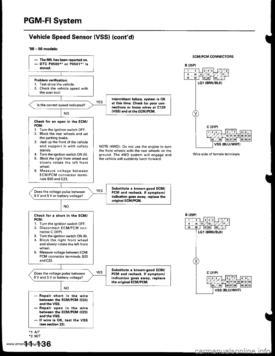
PGM-FI System
Vehicle Speed Sensor (VSSI {cont'd}
'98 - 00 models:
ECM/PCM CONNECTORS
B t25Pl
NOTE (4WD): Do not use the engine to turnthe front wheels with the rear wheels on theground. The 4WD system will engage andthe vehicle will suddenly lurch forward.
Wire side of female terminals
- The MIL ha3 been reDoned on.- DTC P0500" or P0501*1 i33torod.
Probl6m verification:1. Test-drive the vehicle.2. Check the vehicle speed withthe scan tool,
Intermittont failu.e, svstem is OKat thk time. Check for poor con-nection! or loose wiros at C129lvss) .nd ar the EcM/PcM.
ls the correct speed indicated?
Check for rn open in the ECM/PCM:l� Turn the ignition switch OFF.2. Elock the rear wheels and setthe parking brake.3. Jack up the front oI the vehicleand support it with satetystands.4. Turn the ignition switch ON {ll}.5. Block the right front whoel andslowly rotate the lett front
6. Measure voltage betweenECM/PCM connector termi-nals 820 and C23.
Substitute a known-good ECM/PCM and rochock. ll symptom/indicetion 9063 away, .oplace th€origin.l ECM/PCM.
Does the voltage pulse between0 V and 5 V or battery voltage?
Check for a short in the ECM/PCMI1. Turn the ignition switch OFF.2. Disconnect ECM/PCM connector C 131P).3. Turn the ignition swilch ON {ll).4. Block the right front wheeland slowly rotate the left front
5. Moasure voltage between ECM/PCM connector terminals 820and C23.
Sub.titute a known-good ECM/PCM and rschock. It rymptom/indication goos .w.y. replecerhe original ECM/PCM.
Does the voltage pulse betlveen0 V and 5 V or battery voltage?
- R.pair short in the wirobetwe€n the ECM/PCM lC23).nd tho VSS.- Roprir open in th6 wirebotweon the ECM/PCM lc23land th6 vss.- It wirc is OK, te3t ihe VSS(!€e soetion 23).
B (25P)
1
*2:Mft
1-136
www.emanualpro.com
Page 351 of 1395
ldle Control System
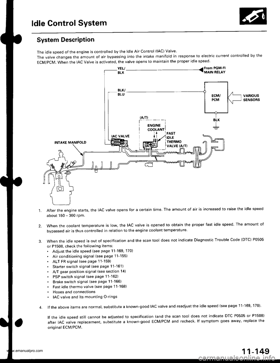
System Description
The idle speed of the engjne is controlled by the ldle Air Control (lAC) Valve'
The valve changes the amount of air bypassing into the intake manifold in response to electric current controlled by the
ECM/PCM. When the lAc valve is activated, the valve opens to maintain the proper idle speed.
YEL/ From PGM'FI
BLK TMAIN RELAY
VARIOUSSENSORS
4.
IAC VALVE
INTAKE MANIFOLD
After the engine starts, the IAC valve opens for a certain time. The amount of air is increased to raise the idle speed
about 150 - 300 rpm.
when the cootant temperature ts row, the lAc valve is opened to obtain the proper fast idle speed The amount o{
bvoassed air is thus controlled in relation to the engine coolant temperature
When the idle speed is out o{ specification and the scan tool does not indicate Diagnostic Trouble Code (DTC) P0505
or P1508, check the following items:
. Adjust the idle speed (see page 11-169, 170)
. Air conditioning signal (seepagell-1551
. ALT FR signal (see page 1l-159)
. Starter switch signal (see page 11-16'1)
. A,/T gear position signal (see section 14)
. PSP switch signal (seepagell-162)
. Brake switch signal (see page 11-165)
. Fast idlethermovalve (see page'11 168)
. Hoses and connecttons. IAC valve and its mounting O-rings
lf the above items are normat, suDslitute a known-good IAC valve and readjust the idle speed {see page 11-169, 170)
lf the idle speed still cannot be adjusted to specification (and the scan tool does not indicate DTC P0505 or Pl508)
after IAC valve reolacement, substitute a known-good ECM/PCM and recheck lf symptom goes away' replace the
original ECM/PCM.
11-149
www.emanualpro.com
Page 368 of 1395
ldle Control System
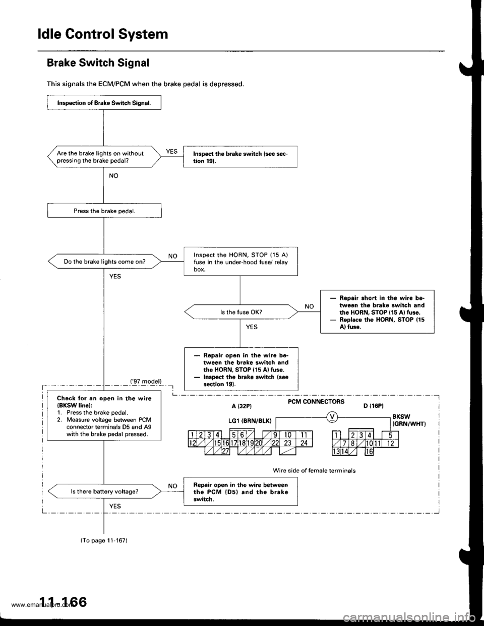
Brake Switch Signal
This signals the ECM/PCM when the brake pedal is depressed.
('97 model)'- - - - -_- Il
PCM CONNECTORSa t32P) D ll6Pl
BKSW(GRN/WHT)
Wire side of female terminals
Insp€ction of Brak. Switch Signal.
Are the brake lights on withoutpressing the brake pedal?
Inspect the HORN, STOP {15 A)fuse in the undeFhood luse/ relaybox.Do the brake lights come on?
Reoair short in the wire be-tween th€ b.ake switch andth6 HoRN, STOP {15 A)luso,Replaco the HoRN, STOP (15
Al fuse.
Repair op6n in the wir€ be-tween the brake switch andtho HORN, STOP (15 Allus6.Inspect the brrke switch (see
aection l9l.
Check tol .n open in the wire{BXSW linel:1. Press the brake pedal.2. Measure voltage between rcMconnector terminais D5 and Agwith the brake pedal pressed.
Reprir open in the wire betweenthe PcM lD5l rnd the brakeswitch.
(To page 11-167)
1 1-166
www.emanualpro.com
Page 369 of 1395
(From page 11-166)
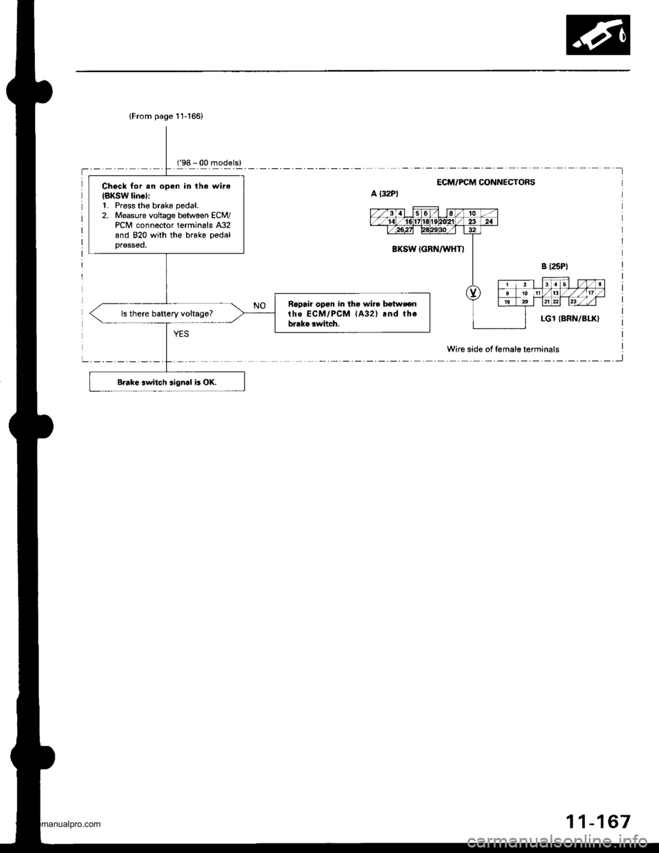
Chock for en open in the wire(BKSW line):1. Press the brake pedal.
2. Measure vohage between ECM/PCM connector terminals A32and 820 with the brake pedalpressed.
Ropair opon in tha wire bstwsonrhe ECM/PCM lA32l rnd thebrako switch.
Brake switch signd b OK.
ECM/FCM OONNECTORS
Wire side of femalo terminals
11-167
www.emanualpro.com
Page 371 of 1395
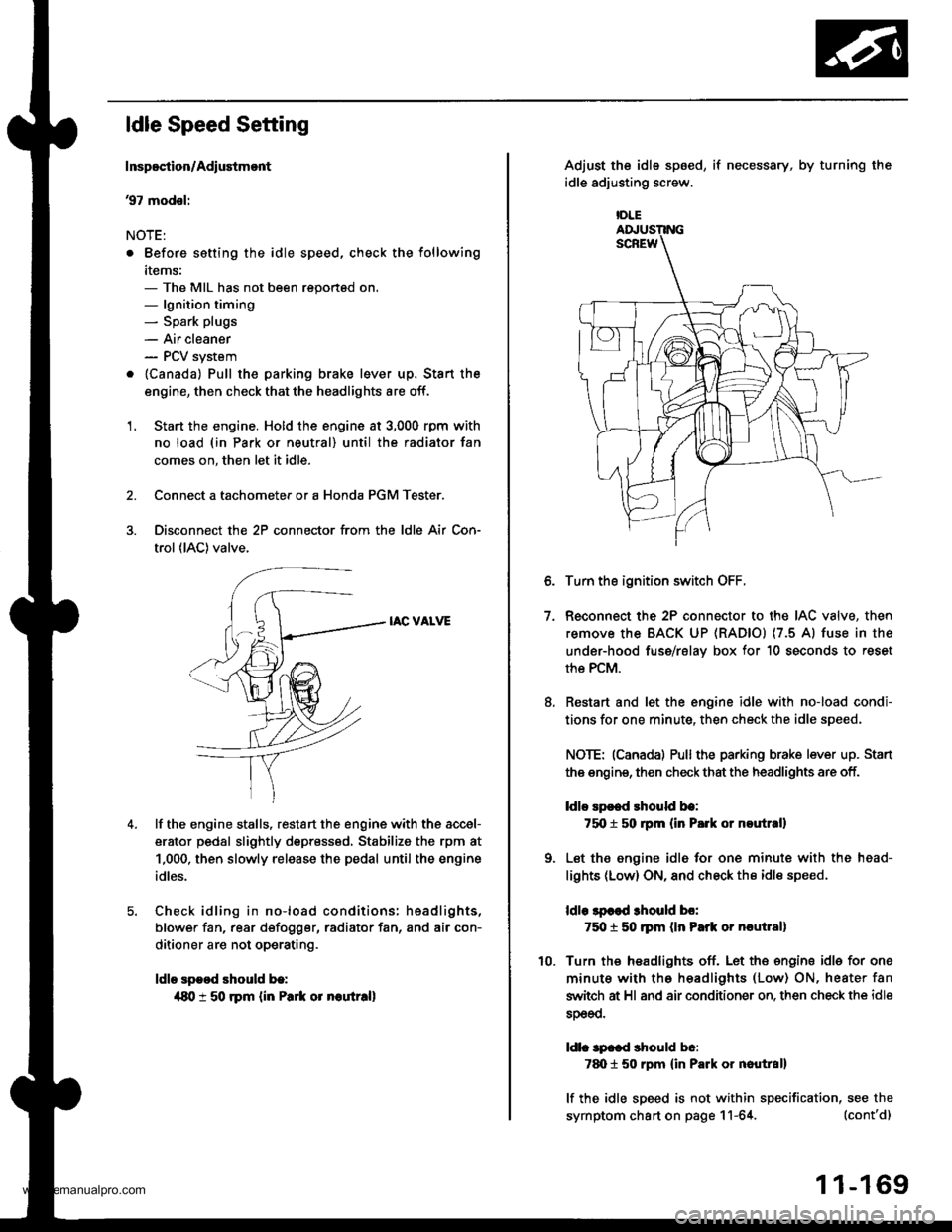
ldle Speed Setting
Inspoction/Adiustmont
37 modsl:
NOTE:
. Before setting the idle speed, check the following
items:- The MIL has not been reportsd on.- lgnition timing- Spark plugs
- Air cleaner- PCV system
. lcanada) Pull the parking brake lever up. Stan the
engine, then check that the headlights are off.
1. Start the engine. Hold the engine at 3,000 rpm with
no load (in Park or neutral) until the radiator fan
comes on, then let it idle.
Connect a tachometer or a Honda PGM Tester.
Disconnect the 2P connector from the ldle Air Con-
trol (lAC) valve.
IAC VALVE
lf the engine stalls, restart the engine with the accel-
erator pedal slightly depr6ss6d, Stabilize the rpm at
1,000, then slowly release the pedal until the engine
idles.
Check idling in no-load conditions: hsadlights,
blower fan, rear d€fogger, radiator fan, and air con-
ditioner are not operating.
ldle spood should b.:
{80 t 50 rpm {in Park or noutr.ll
IDLE
7.
Adjust the idle sp6ed,
idle adjusting screw.
if necessary, by turning the
Turn the ignition switch OFF.
Reconnect the 2P connector to the IAC valve, then
remove the BACK UP (RAD|Ol (7.5 Al fuse in the
under-hood fuse/rslav box for 10 seconds to reset
the PCM.
Restart and let the engine idle with no-load condi-
tions for one minute, then check the idle speed.
NOTE: (Canadal Pullthe parking brake lever up. Stan
the engine, then check that the headlights are off.
ldlo Ep€ed rhould be:
75O t 50 rpm (in P.rk or noutr.ll
Let the engine idl6 for one minute with the head-
lights (Low) ON, and check th€ idl€ speed.
ldle lpcod 3hould bo:
750 t 50 ]pm (in Park or nautlal)
Turn the headlights off. Let th€ engine idle for one
minute with the headlights (Low) ON, heater fan
switch at Hl and air conditioner on. then check the idle
sDeeo.
ldl. specd should b6:
7d) 1 50 rpm {in Park or nautral}
lf the idle speed is not within specification, see the
symptom chart on page 11-64. (cont'd)
1 1-169
www.emanualpro.com
Page 446 of 1395
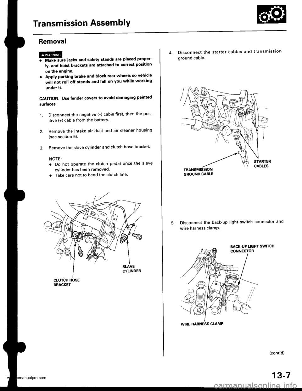
Transmission AssemblY
Removal
@FMak. sw. iack" and safety stands are placed propel-
ly, and hoist brackets are attached to collect position
on the engine,
. Apply parking brake and block rear wheels so vehicle
will not roll off stands and lall on you while working
under it.
CAUTION: Use fender covers to avoid damaging painted
surfaces.
1. Disconnect the negative {-) cable first, then the pos-
itive (+) cable from the batterY.
2. Remove the intake air duct and air cleaner houslng
(see section 5).
3. Remove the slave cylinder and clutch hose bracket'
NOTE:
. Do not operate the clutch pedal once lhe slave
cvlinder has been removed.
. Take care not to bend the clutch line.
4. Disconnect the
ground cable.
starter cables and transmission
TRANSMISSIONGROUND CABLE
Disconnect the back-up light switch connector and
wire harness clamP.
(cont'd)
13-7
WIRE HARNESS CLAMP
www.emanualpro.com
Page 534 of 1395
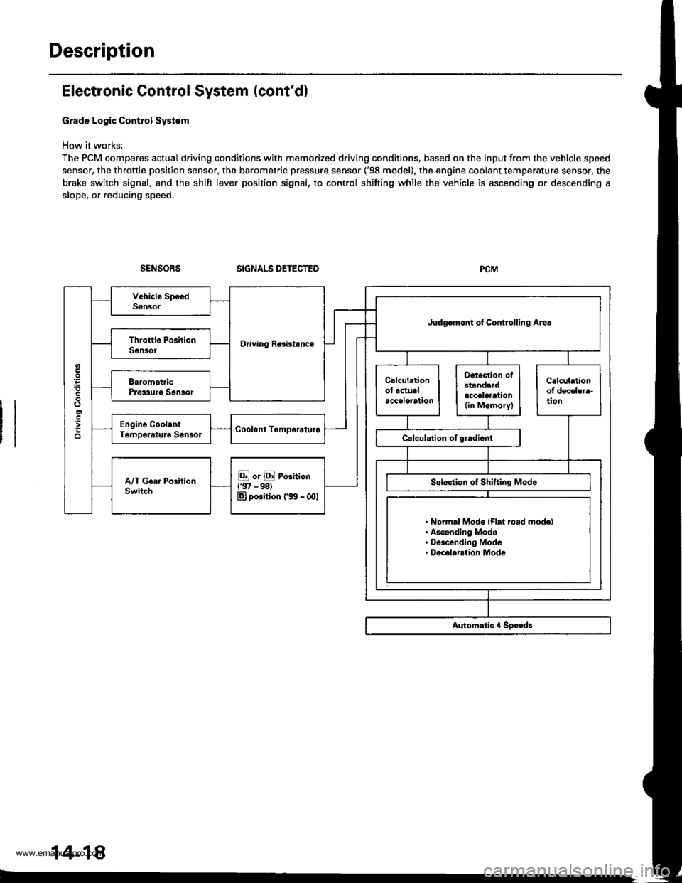
Description
Electronic Control System (cont'dl
Grade Logic Control System
How it works:
The PCM compares actual driving conditions with memorized driving conditions, based on the input from the vehicle speed
sensor, the throttle position sensor, the barometric pressure sensor ('98 model). the engine coolant temperature sensor, the
brake switch signal, and the shift lever position signal, to control shifting while the vehicle is ascending or descending a
slope, or reducing speed.
SIGNALS DETECTED
Driving Rcsisl.nce
Judgemont ot Controlling Aroa
. Normal Modo {Flrt ro.d mode}. Ascending Mode. Deacending Mode. Deceleration Mode
14-14
www.emanualpro.com
Page 565 of 1395

PCM CONNECTOR B (25P) lcont'd)
PCM CONNECTOR C {31PI
PCM CONNECTOR D II6PI
Terminal NumbelSignalDescriptionMeasuring Conditions/Terminal voltage
811SHBShift control solenoid valve B
control
In E, E position, in 1st and 2nd gear in -q,
Er position: Battery voltage
In B position, in 3rd gear in qd, q:l,in atn
gear in D. position: 0 V
812ILUlnterlock controlWhen ignition switch is ON (ll), brake pedal
deDressed and accelerator oedal released:0 V
B13D4 INDD4 Indicator light controlWhen ignition switch is first turned ON (ll): 6 V
or more for tlvo seconds
In lDll position: 6V or more
814NMSGMainshaft speed sensor ground
815NMMainshaft speed sensor signal
InpuI
Depending on engine speed: Pulsing signal
When engine is stopped: 0 V
816ATP RAy'T gear position switch Eposition signal input
In E position; OV
In other than E position: Battery voltage
817ATP 2Ay'T gear position switch E posi-
tion signal input
InEposition:0V
In other than E position: Battery voltage
B18ATP 1A/T gear position switch El posi-
tion signal input
InEposition:0V
In other than E position: Battery voltage
819 to 821Not used
B�22NCSGCountershaft speed sensor ground
NCCountershaft speed sensor signal
Inpur
Depending on vehicle speed: Pulsing signal
when vehicle is stooped: 0 V
824ATP D4A/T gear position switch iql posi-
tion signal input
In E position: 0V
In other than lgal position: Baftery voltage
825ATP NPAy'T gear position switch E and
N position signals input
In E and E positions: 0V
In otherthan @ and ffi positions:5 V
Terminal NumberSignalDescriptionMeasuring Conditions/Terminal Voltage
SCSService check signalWith ignition switch ON (ll) and service check
connector open: 5 V
With ignition switch ON (ll) and service check
connector connected with special tool: 0 V
c10VBUBack-up power system(under-hood Fuse 47)
Always battery voltage
Terminal NumberSignalDescriptionMeasuring Conditions/Terminal Voltage
STOP SWBrake switch signal inputBrake pedal pressedr Battery voltage
Brake pedal released: 0 V
14-49
www.emanualpro.com
Page 570 of 1395

PCM Terminal Voltage/Measuring Conditions
A/T Control System -'98 - 00 Models
The PCM terminal voltage and measuring conditions are shown for the connector terminals that are related to the A"/T con-
trol system. The other PCM terminal voltage and measuring conditions are described in section 11.
FCM Connector Terminal Localions
NOTE: 819 and C3 terminalsare applied to'99 - 00 models.
o (16Pt
T6rminal NumberSignalDescriptionMeasuring Conditions/Terminal Voltage
A5CRSDownshift signal input from
cruise control unit
When cruise control is used; Pulsing signal
A10scsTiming and adjustment service
check signal (5 V from PCM)
With ignition switch ON (ll) and service check
connector open:5 V
With ignition switch ON (ll) and service check
connector jumped with special tool: 0 V
A14('98 model)
D4 INDD4 indicator light control
{Voltage from PCM turns D4 light
oN)
When ignition switch is first turned ON (ll):
Battery voltage for two seconds
In E position: Battery voltage
A14
('99 - 00 models)
D INDD indicator light control(Voltage from PCM turns D light
oN)
When ignition switch is first turned ON (ll):
Baftery voltage for two seconds
ln E position: Battery voltage
428ILUInterlock control(Voltage from PCM)
When ignition switch ON {ll), brake pedal
depressed, and accelerator pedal released:
Battery voltage
A.32STOP SWBrake switch signal inputBrake pedal pressed; Battery voltage
Brake pedal released: 0 V
FCM CONNECTOR B I25P}
Terminal NumberSignalDescriptionMeasuring Conditions/Terminal Voltage
B1IGPlPower supply circuit from main
relay via under-hood Fuse 44
With ignition switch ON {ll): Battery voltage
With ignition switch OFF: 0 V
82PG1Ground (G101)
B8LSMLinear solenoid power supply
negative electrode
IG P2Power supply circuit from main
relay
With ignition switch ON (ll): Baftery voltage
With ignition switch OFF: 0 V
810PG2Ground (G101)
B17Linear solenoid power supply
positive electrode
With ignition switch ON (ll): Pulsing signal
819
('99 - 00 models)
O/D INDOver-Drive (O/D) OFF indicator
light control
When ignition switch is first turned ON (ll):
0 V for two seconds
O/D OFF indicator light ON:0 V
O/D OFF indicator light OFF: Battery voltage
s20Ground (G101)
B�21VBUBack-up power supply(under-hood Fuse 47)
Always battery voltage
B�22LG2Ground (G101)
14-54
www.emanualpro.com
Page 577 of 1395
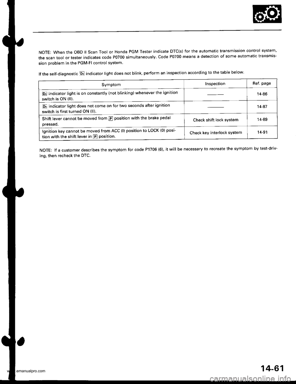
NOTE: When the OBD ll Scan Tool or Honda PGM Tester indicate DTC(s) for the automatic transmission control system'
the scan tool or tester indicates code P0700 simultaneously. code P07oo means a detection of some automatic transmis-
sion problem in the PGM-Fl control system
lf the self-diagnostic E indicator light does not blink, perform an inspection according to the table below.
NOTE: lf a customer describes the symptom for code P1706 (6), it will be necessary to recreate the symptom by test-driv-
ing, then recheck the OTC.
SymptomInspectionRef. page
E indicator light is on constantly (not blinking) whenever the ignition
switch is ON (ll).14-86
E indicator light does not come on for two seconds after ignition
switch is first turned ON (ll).
't 4-41
Shift lever cannot be moved from @ position with the brake pedal
Dressed,Check shift lock system14-89
lgnition key cannot be moved from ACC (l) position to LOCK {0) posi
tion with the shift lever in E position.Check keY interlock system14-91
14-61
www.emanualpro.com