Ignition wires HONDA CR-V 2000 RD1-RD3 / 1.G User Guide
[x] Cancel search | Manufacturer: HONDA, Model Year: 2000, Model line: CR-V, Model: HONDA CR-V 2000 RD1-RD3 / 1.GPages: 1395, PDF Size: 35.62 MB
Page 299 of 1395
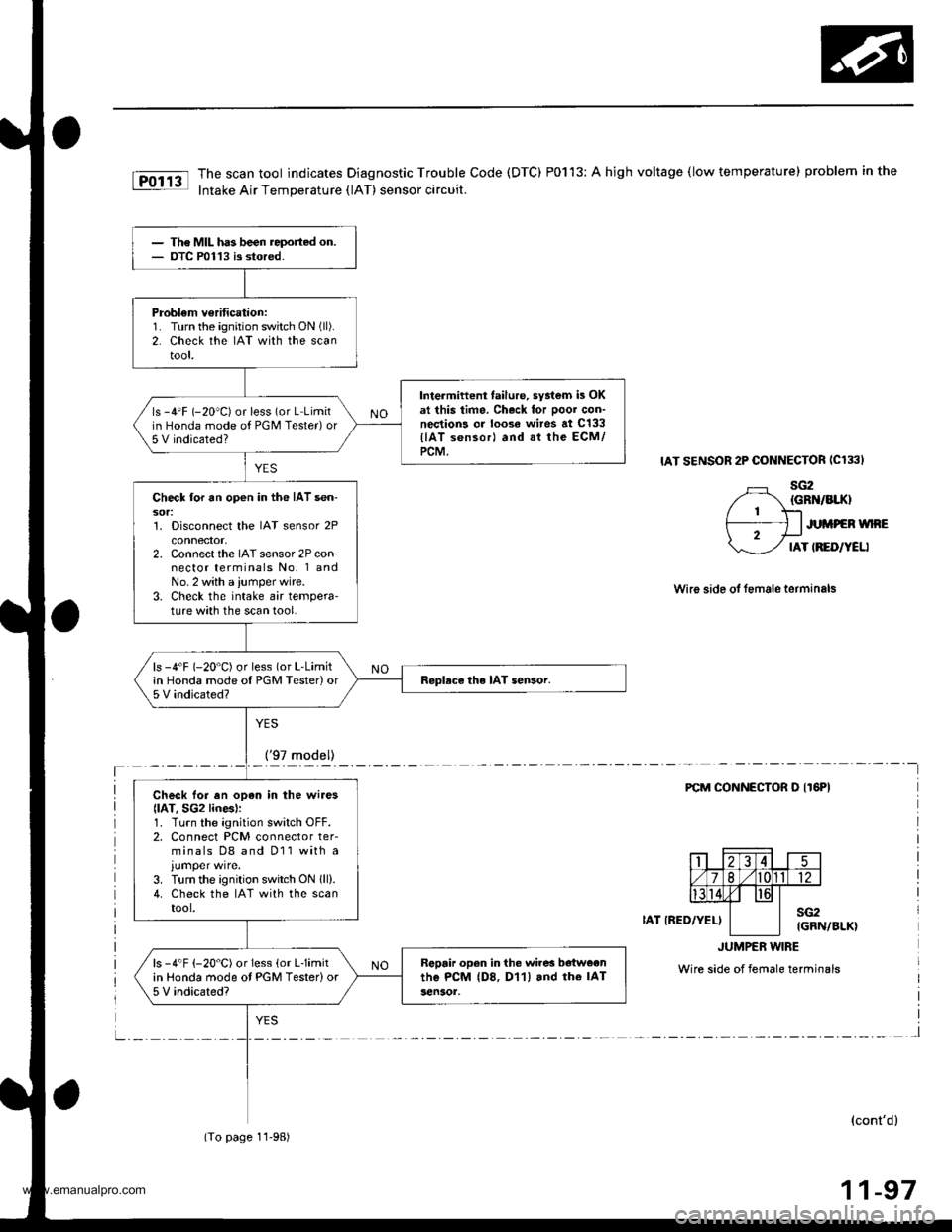
The scan tool indicates Diagnostic Trouble Code (DTC) P0113: A high voltage (low temperature) problem in the
Intake Air Temperature (lAT) sensor circuit.
IAT SENSOR 2P CONNECTOR ICl33I
sG2{GRN/BIIO
JUMPEN WNE
IAT IRED/YELI
Wire side ol female terminals
YES
_!!7rqd9ll_____-
FCM CONNECTOR O IT6PI
IAT IRED/YEL)sG2IGRN/BLK}
JUMPER w|BE
Wire side of female terminals
l
(cont'd)
11-97
The MIL has been reported on.OTC P0113 is stored.
Problem v€rification:1. Turn the ignition switch ON (ll).
2. Check the IAT with the scantool,
Intermiftent failure, syatem is OKat this time. Ch.ck for Door con-nections or loose wires at c133
llAT s6nsorl and at the ECM/PCM.
ls -4'F (-20"C) or less (or L Limitin Honda mode of PGM Tester)or5 V indicated?
Check lor an open in the IAT sen-sor:1. Disconnect the IAT sensor 2Pconnector,2. Connect the IAT sensor 2P connector terminals No. 1 andNo. 2 with a ,umper wire.3. Check the intake air tempera'ture with the scan tool.
ls -4'F (-20"C) or less (or L-Limitin Honda mode oI PGM Tester)or5 V indicated?Replace the IAT sensor.
Check lor en opan in the wires
llAT, SG2 lines):1. Turn the ignition switch OFF.2. Connect PCM connector ter-minals D8 and D11 with a
3. Turn the ignition switch ON lll).4. Check the IAT with the scantool.
Rgpair open in the wires b€tweenthe PcM (D8. D11) and rhe IAT3en30r,
ls -4"F {-20"C) or Iess (or Llimitin Honda mode ot PGM Tester)or5 V indicated?
(To page 11-98)
www.emanualpro.com
Page 300 of 1395
PGM-FI System
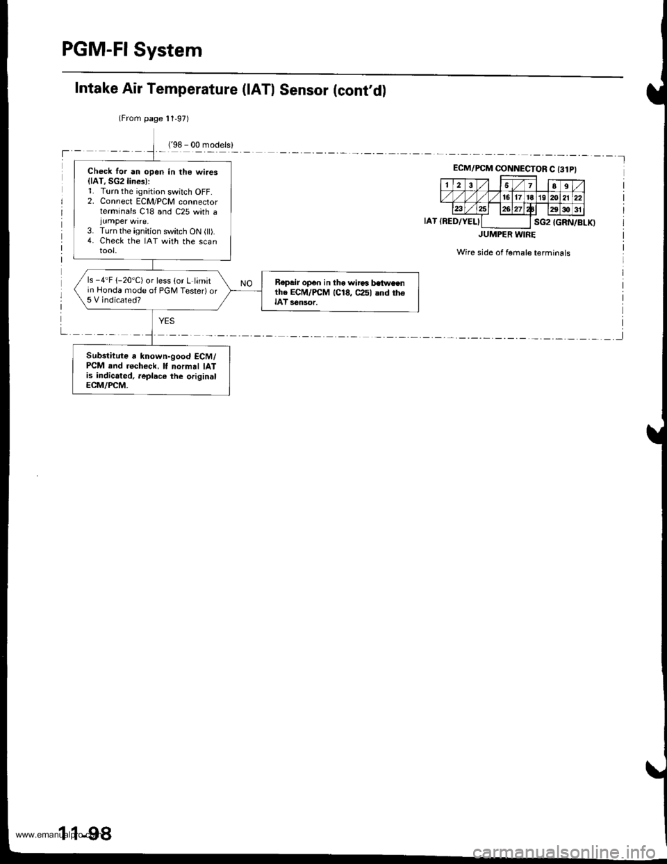
Check for an open in the wires{lAT, SG2lines):1. Turn the ignition switch OFF.2. Connect ECM/PCM connectorterminals C18 and C25 with ajumper wire.3. Turn the ignition switch ON (ll).4. Check the IAT with the scantool.
ls -4'F 1-20"C) or less (or L limitin Honda mode of PGM Testeri or5 V indicated?
Repsir op€n in the wirca batweenthe ECM/PCM 1C18, C25l and theIAT s€nsor.
Substitute a known-good ECM/PCM rnd recheck, lf normal IATis indicated, leplaco the originslECM/PCM.
Intake Air Temperature (lATl Sensor (cont'd)
(From page 11,97)
'l
ECM/PCM CINNECTOR C t3lPl
257II
./ 16171819 202122234 Wp,29c)31
sG2IAT {RED/YELI{GRN/BLK)
JUMPER WIRE
Wire side of fernale terminals
I
1 1-98
www.emanualpro.com
Page 303 of 1395
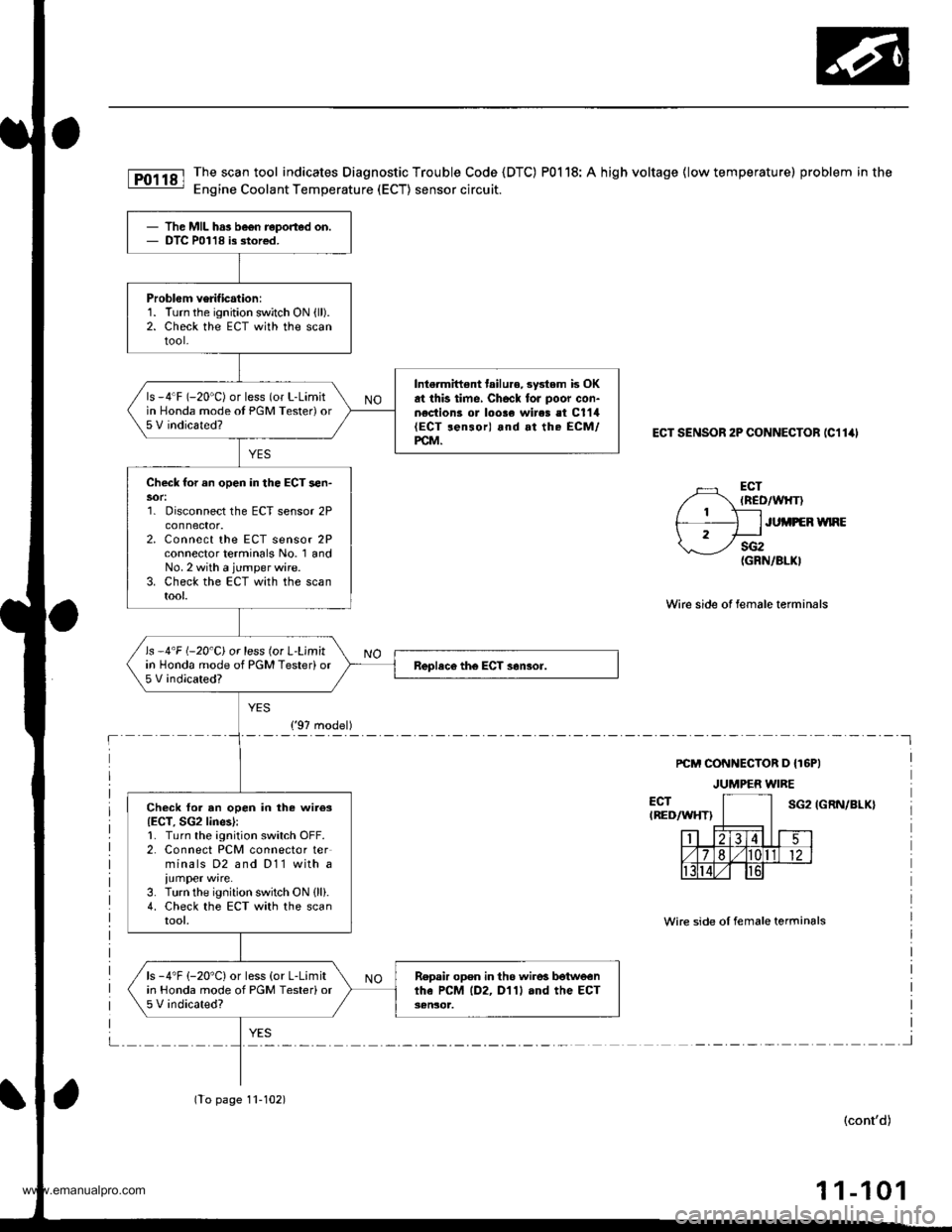
The scan tool indicates Diagnostic Trouble Code {DTC) P0118: A high voltage {low temperature) problem in the
Engine Coolant Temperature (ECT) sensor circuit.
ECT SENSOR 2P CONNECTOB (C11ill
ECT(ncD/wlrT)
ECTIREDAAIHT)
Wirc side of lemale terminals
sG2(GRN/8LKI
PCM CONNECTOR D {T6PI
JUMPER WIRE
JUi,IPEB WNE
IGRN/BLX}
Wire side oI female terminals
(cont'd)
1 1-101
The MIL has be€n reported on.DTC P01'18 is stor€d.
Problem verification:1. Turn the ignition switch ON {ll).2. Check the EcT with the scantool-
Intermiftent tailu.€,3ystem is OKat this time, Checl foJ poor con-n€ction3 or loose wires et C1'14(ECT ren3or) and at the ECM/PCM.
ls -4"F (-20'C) or less (or L-Limitin Honda mode ot PGM Tester) or5 V indicated?
Check for an open in the ECT sen-
1. Disconnect the ECT sensor 2Pconnector.2. Connect the ECT sensor 2Pconnector terminals No. 1 andNo. 2 with a jumper wire.3. Check the ECT with the scantool.
ls -4'F (-20'C) or less (or L'Limitin Honda mode of PGM Tester)or5 V indicated?
Check for an open in the wiies{ECT, SG2 lines):1. Turn the ignition switch OFF.2. Connect PCM connector terminals D2 and D11 with a
iumper wire.3. Turn the ignition switch ON {ll}.4. Check the ECT with the scantool,
ls -4"F (-20'C) or less (or L-Limitin Honda mode of PGM Testerior5 V indicated?
Repair open in th6 wire! botwe€nthe PCM lD2, D'l1l and the ECT3€n30t.
('97 model)
(To page 11-102)
www.emanualpro.com
Page 304 of 1395
PGM-FI System
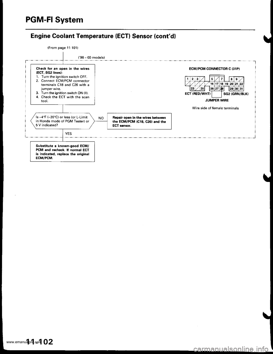
Chack lor an open in the wires(ECT, SG2 lines):1. Turn the ignition switch OFF.2. Connect ECM/PCM connectorterminals C18 and C26 with a
3. Turn the ignition switch ON (ll).
4. Check the ECT with the scantool.
ls -4"F (-20"C) or less (or L-Limitin Honda mode of PGM Testerlor5 V indicated?
Ralpair open in tho wir6s b6twe€ntho ECM/PCM 1C18, c26l 6nd thoECT sensor.
Substitute a known-good ECM/PCM and rech.ck. lf normal ECTis indicrted, replace ths originslECM/PCM.
Engine Goolant Temperature (ECTI Sensor (cont'dl
(From page 11 101)
ECM/PCM OONNECTOR C 13lPI
(GRN/BLK)
JUMPER WIRE
Wire side of temale terminals
17I9
,/ 1617't8'1920n
ECT IRED/WHTIsG2
11-102
www.emanualpro.com
Page 307 of 1395
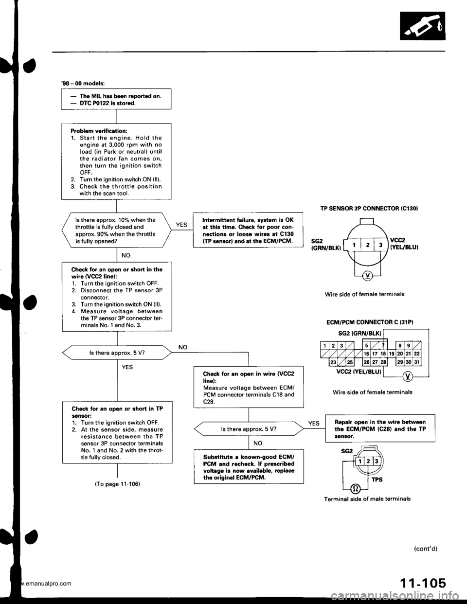
'98 - 00 model3:
The MIL has boon reDortod on.DTC m122 b rtorod.
P.oblom veiification:1. Start the engine. Hold theengine at 3,000 rpm with noload (in Park or neutral) untilthe radiator tan comes on,then turn the ignition switchOFF.2. Turn the ignition switch ON lll).3. Check the throttle position
with the scan tool.
ls there approx. 10% when thethrottle is fully closed andapprox. 90% when the throttleis fully opened?
Intarmittent failure. system is OKat thia time. Check for poor con-n€ctions or loolo wires rt C130ITP s.nsorl and.t the ECM/FCM.
Check for an opon or short in thowire {VCC2 linel:1. Turn the ignition switch OFF.2. Disconnect the TP sensor 3Pconnedor,3. Turn the ignition switch ON (ll).
4. Meas! re voltage betweenthe TP s€nsor 3P connector ter-minals No. 1 and No.3.
ls there approx. 5 V?
Check lor an opon in wiro IVCC2linel:Measure voltage between ECM/rcM connector terminals C'18 andc2a.Chock for en op€n or Bhort in TP3an30r:1. Turn the ignition switch OFF.2. At the sensor side, measureresistance between the TPsensor 3P conneclor terminalsNo. 1 and No. 2 with the throt-tle fully closed.
B.psir opon in the wire b€{woontho ECM/PCM {C281 and th6 TP3en!xtt.ls lher€ approx. 5 V?
Subslitute e known-good ECM/PCM .nd r.chock. lf pro3cribedvoltrge iB now rYrilablo, replacath. originll ECM/PCM.
TP SENSOR 3P CONNECTOR {C130}
sG2IGRN/BLKI
vcc2IYEUBLUI
Wire side oI Iemale lerminals
Wire sid6 of temale terminals
Terminal side of male torminals
(cont'd)
1 1-105
ECM/PCM CONNECTOR C (31P}
sG2IGRN/BLKIa-,l 18 sl./|135
/1617lrs]zolzr zzl
232527)gJ lzgi3o sr I
T^vccz {YEL/8LUl
(To page 11-106)
www.emanualpro.com
Page 315 of 1395
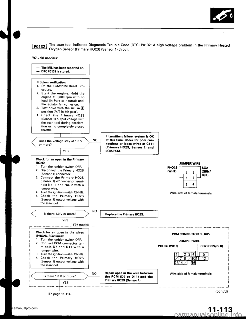
The scan tool indicates Diagnostic Trouble Code (DTC) P0132: A high voltage problem in the Primary HeatedOxygen Sensor {Primary HO2S) (Sensor 1) circuit.
'97 - 98 models:
PHO2S
IWHTIsG2IGRN/BLK}
Wire side ot female terminals
PCM CONNECTOR D {16PI
JUMPER WIRE
PHO2S IWHTISG2 IGRN/BLK}
Wire side of temale terminals
I
(cont'dl
11-113
Problem verification:1. Do the ECM/PCM Resot Pro,ceoute,2. Start the engine. Hold theengine at 3,000 rpm with noload (in Park or neutral) untilthe radiator fan comes on.3. Test-drive with the Ay'T in Eposition (M/T in 4th gear).4. Check the Primary H02S{Sensor 1}output voltage withthe scan tool during decelera-tion using completely closedthrottle.
Intormittent l.ilure, 3ystem ia OKat thb timo. Chcck fo. poor con-nections 01 looso wi.es at C111{Prim!ry HO2S, Sensor 1} andECM/PCM.
Does the voltage stay at 1.0 V
Check for an open in th6 PrimaryH()2S:1. Turn the ignition switch OFF.2. Disconnect the Primary HO2S(Sensor 1) connector-3. Connect the Primary HO25lSensor 1) 4P connector termi-nals No. 1 and No. 2 with ajumper wire.4. Turn the ignition switch ON (ll).5. Check the Primary HO2S(Sensor 1) output voltage withthe scan tool,
ls there 1.0 V or more?
Ch€ck for an opon in the wires(PHO2S, SG2linesl:1. Turn the ignition switch OFF.2. Connect PCM connector ter-minals D7 and Dl1 with a
3. Turn the ignition switch ON (ll).4. Check the Primary HO2S{Sensor 1) output voltage withthe scan tool.
Roprir opon in the wire betweontho PCM {D7 01 D11l and thePrimsry HO2S {S6nsor 1).
ls there 1.0 V or more?
{'97 model}
{To page 11-114)
www.emanualpro.com
Page 319 of 1395
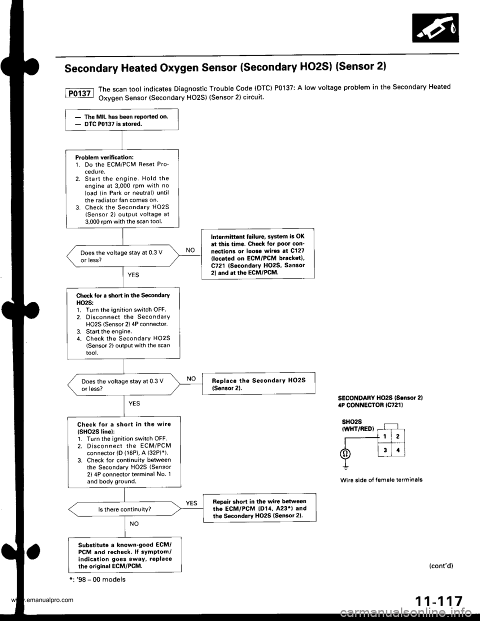
Secondary Heated Oxygen Sensor (Secondary HO2S) (Sensor 2)
The scan tool indicates Diagnostic Trouble code (DTC) P0137: A low voltage problem in the secondary Heated
Oxygen Sensor (Secondary HO2S) (Sensor 2) circuit.
SECONDARY HO2S ls.nlor 2)4P CONNECTOB lC721l
Wire side of lemale terminals
(cont'd)
11-117
The MIL hrs been reported on.DTC P0137 is stored.
Problem veritication:1. Do the ECM/PCM Reset Pro'cedure.2. Start the engine. Hold theengine at 3,000 rpm wilh no
load (in Park or neutral) untalthe radiator {an comes on,3. Check the Secondary H02S
lSensor 2) output voltage at3,000 rpm with the scan tool.
lnlermittent failure, 3ystem i5 OK
at this time. Check tor Poor con'
noction3 or loose wires at C127
{locatod on ECM/PCM bracket},C721 (Secondary HO2S, Sensor2l and at the ECM/PCM.
Does the voltage stay at 0.3 V
or less?
Check for a short in the SecondaryHO2S:1. Turn the ignition switch OFF.2. Disconnect the SecondaryHO2S lSensor 2) 4P connector.3. Start the engine.4. Check the Secondary HO25(Sensor 2) output with the scantool.
Check lor a short in the wire(SHO2S linel:1. Turn the ignition switch OFF.2. Disco n nect the ECM/PCMconnector {D (16P}, A (32P}').
3. Check for continuity betweenthe Secondary HO2S (Sensor
2i 4P connector terminal No. 1and body ground.
Reoair short in the wire b€twoen
rhe ECM/PCM |D14, 423*l and
the Secondary HO2S {Sensor 2).
Substitute a known-good ECM/PCM and rocheck. lf symptom/indication goes away, replacethe original ECM/PCM.
*: '98 - 00 modeis
www.emanualpro.com
Page 323 of 1395
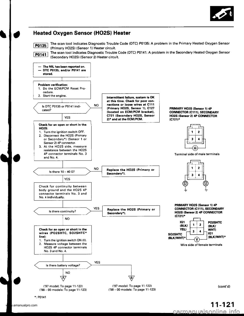
Heated Oxygen Sensor (HO2S| Heater
The scan tool indicatos Diagnostic Trouble Code (DTC) P0135: A problem in the Primary Heated Oxygen Sensor
{Primarv HO2S) (Sensor 1) Heater circuit.
The scan tool indicates Diagnostic Trouble Code (DTC) P0141: A problem in the Secondary Heated Oxygen Sensor
(Secondary HO2S) (Sensor 2) Heater circuit.
Fol3sl
Fo11tl
PBIMARY HO2S ls.n.or ll 4PCONNECTOR (CI 1 1 I, SECONDARYHO2S ls.n.o.2l aP CONNECTORlc721l.
Terminal side of male t€rminals
PRIMARY HO2S lson.o. 1l aPCONNECTOR {Cl 1 1 }, SECONDARYHO2S ls.nror 21 4P CONNECTORtcr21l.
so2sHTctBLK/WHn.
PO2SHTC(BLK/
WHTItGlIBLKAAIHTI'
Wire sid€ of lemale terminals
('97 model: To page '11-122)
('98 - 00 models: To page 11-'123)
*: P0141
('97 model: To page'11-122)
1'98 - 00 modelsl To page 11-123)(cont'd)
11-121
- Th6 MIL h.. bocn roponod on.- DTC P0135, and/oi mlal arestored.
Probl.m verification:1. Do the ECM/PCM Resot Pro-cedure,2. Start the engine.Int.rrnittaii frilurc, awtom ir OKat thi3 time. Chock lor poor con-n.ctiona or loosa wiro3 !t C111
lPrim.ry HO2S, Sen3o. 11. C12?llocatcd on ECM/PCM br.ck.t),C721 lsocond.ry Ho2s, s.n3or2r and at tho ECM/PCM.
Ch.ck ior an opon or shoYt in theHO2S:1. Turn the ignition switch OFF.2. Disconnoct the Ho2s (Primary
or Secondary*) (Sensor 1 orSensor 2)4P conneclor.3. At the HO2S side, measureresistance between the HO2S4P connector terminals No. 3and No.4.
ls there 10 - 40 0?
Check for continuity betweenbody ground and the HO2S 4Pconnector terminals No. 3 andNo. 4 individually.
Check tor an op6n or 3hort in thewires IPO2SHTC, SO2SHTC'linel:1. Turn the ignition swhch ON {ll).2. Moasure voltage between theHO2S 4P connector terminalsNo.3 and No.4.
www.emanualpro.com
Page 325 of 1395
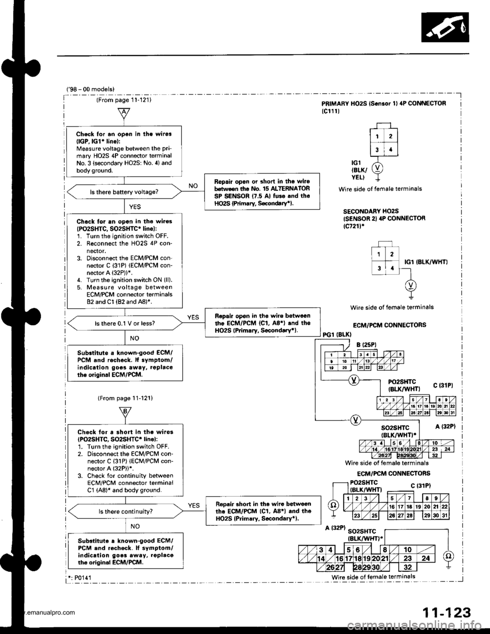
Check for an open in the witoa(lGP,lGl'lino):
Mgasure voitage between the pri-
mary HO2S 4P connector terminalNo. 3 (secondary HO2S: No. 4) andbody ground.
Bepair opan or short in tho wilobdtween th6 nlo. 15 ALTERNATORSP SENSOR 17.5 Al fu$ .nd th6HO2S {Primrry, S€condtrytl.
Chock lor sn opon in the wires
IPO2SHTC, SO2SHTC' lincl:1. Turn the ignition switch OFF.2. Reconnect the HO2S 4P con-nector.3. Disconnect the ECM/PCM con-nector C (31P) (ECM/PCM con-neaor A (32P))*.
4. Turn the ignition switch ON (ll).
5. Moasure voltage betweenECM/PCM connector terminals82 and Cl (82 and A8)*.
Repsir opsn in tha wire betweentho ECM/PCM (C1, A8.) .nd theHO2S lPrimsry, Socond.ry*}.ls there 0.1 V or less?
Sub.titute a known-good ECM/PCM and rocheck. lf iymptom/indicrtion goes away, repbcethe original ECM/PCM.
('98 - 00 models)
Wire side of female terminals
ECM/FCM CONNECTORS
IGl IBLK/WHT}
PRIMARY HO2S {S.n3or 1l aP CONNECTOR
lc111l
11 2l
r--T -l3t.lL-.IJ------J
lcl /5'tErK/ g,YELI I
Wire side of female terminals
SECONDARY HO2S
{SENSOR 2} 4P CONNECTOR(c7211'
PGl (BLK}
lFrom page 11-12'!)
Chock lor a short in the wi.es(PO2SHTC, SO2SHTC' linol:1. Turn the ignition switch OFF.2. Disconnect the EcM/PcM con-nector C {31P) lECM/PCM con-nector A (32P))*.
3. Check for continuity betweenECM/PCM connector terminalCl (A8)* and body ground.
Roolir 3hort in th. wiro betwoonthe ECM/PCM lC1, A8'l and theHO2S (Primary, S6condary*).ls there continuity?
Sub3tituie s known-good ECM/PCM and rech6ck. It symptom/indicaiion goes away. lgplacoth6 origin.l ECM/PCM.
Wire side of lemale terminals: P0'14'l
11-123
www.emanualpro.com
Page 334 of 1395
PGM-FI System
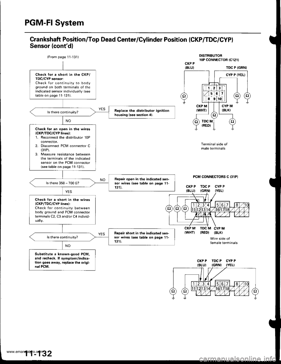
Grankshaft Position/Top Dead Center/Cylinder Position (CKP/TDC/CYPI
Sensor (cont'd)
DISTRIBUTOR10P CONNECTOR tCl2l)CKP P
IBLUITDC P {GRNI
PCM CONNECTORS C I31P)
CKP P TDC P CYP PIBLU) IGRNI IYEL}
Terminal side ofmale terminals
IREDI IBLK)
Wire side offemale terminals
{WHT)
{From page 1'1-131)
Check for a short in the CKP/TDC/CYP sensor:Check for continuity to bodyground on both terminals of theindicated sensor individually (see
table on page 1l 131).
R€plac€ the distributor ignitionhousing {see section 4}.ls there continuity?
Ch€ck fo. an open in the wires{CKP/TDC/CYP lines):'1. Reconnect the distributor 10Pconnector.2. Disconnect PCM connector C(31P).
3. Measure resistance betweenthe terminals of the indicatedsensor on the PCM connectorlseetable on page 1l 131).
Repair open in the indicated sen-sor wires {se6 table on page 11-131).ls there 350 - 700 0?
Check tor a short in the wires{CKP/TDC/CYP linesllCheck for continuity betweenbody ground and PCM connectorterminals C2, C3 and/or C4 individ-
R€Dair short in the indicatod sen-sor wires lsee table on page 11-13rI.ls there continuity?
Substitute a known-good PCM,and recheck. lf symptom/indica-tion goes away, r€place lhe origi-nal PCM.
CKP P TDC P CYP P
www.emanualpro.com